EP1160902B1 - Système de pile à combustible - Google Patents
Système de pile à combustible Download PDFInfo
- Publication number
- EP1160902B1 EP1160902B1 EP01113017A EP01113017A EP1160902B1 EP 1160902 B1 EP1160902 B1 EP 1160902B1 EP 01113017 A EP01113017 A EP 01113017A EP 01113017 A EP01113017 A EP 01113017A EP 1160902 B1 EP1160902 B1 EP 1160902B1
- Authority
- EP
- European Patent Office
- Prior art keywords
- fuel
- evaporator
- gas
- reforming
- fuel cell
- Prior art date
- Legal status (The legal status is an assumption and is not a legal conclusion. Google has not performed a legal analysis and makes no representation as to the accuracy of the status listed.)
- Expired - Lifetime
Links
- 239000000446 fuel Substances 0.000 title claims description 130
- 238000002407 reforming Methods 0.000 claims description 82
- 239000007789 gas Substances 0.000 claims description 51
- 238000009835 boiling Methods 0.000 claims description 38
- 239000002737 fuel gas Substances 0.000 claims description 38
- 239000001257 hydrogen Substances 0.000 claims description 22
- 229910052739 hydrogen Inorganic materials 0.000 claims description 22
- UFHFLCQGNIYNRP-UHFFFAOYSA-N Hydrogen Chemical compound [H][H] UFHFLCQGNIYNRP-UHFFFAOYSA-N 0.000 claims description 19
- 230000005611 electricity Effects 0.000 claims description 13
- 238000000034 method Methods 0.000 claims description 13
- 239000002828 fuel tank Substances 0.000 claims description 9
- 238000001704 evaporation Methods 0.000 claims description 7
- OKKJLVBELUTLKV-UHFFFAOYSA-N Methanol Chemical compound OC OKKJLVBELUTLKV-UHFFFAOYSA-N 0.000 description 25
- UGFAIRIUMAVXCW-UHFFFAOYSA-N Carbon monoxide Chemical compound [O+]#[C-] UGFAIRIUMAVXCW-UHFFFAOYSA-N 0.000 description 24
- 229910002091 carbon monoxide Inorganic materials 0.000 description 24
- 238000006243 chemical reaction Methods 0.000 description 22
- 230000001276 controlling effect Effects 0.000 description 9
- 229920000642 polymer Polymers 0.000 description 9
- 239000007787 solid Substances 0.000 description 9
- 239000003054 catalyst Substances 0.000 description 5
- 230000001105 regulatory effect Effects 0.000 description 5
- QVGXLLKOCUKJST-UHFFFAOYSA-N atomic oxygen Chemical compound [O] QVGXLLKOCUKJST-UHFFFAOYSA-N 0.000 description 4
- 239000001301 oxygen Substances 0.000 description 4
- 229910052760 oxygen Inorganic materials 0.000 description 4
- 150000002431 hydrogen Chemical class 0.000 description 3
- 238000007254 oxidation reaction Methods 0.000 description 3
- XLYOFNOQVPJJNP-UHFFFAOYSA-N water Substances O XLYOFNOQVPJJNP-UHFFFAOYSA-N 0.000 description 3
- WSFSSNUMVMOOMR-UHFFFAOYSA-N Formaldehyde Chemical compound O=C WSFSSNUMVMOOMR-UHFFFAOYSA-N 0.000 description 2
- 238000010586 diagram Methods 0.000 description 2
- BASFCYQUMIYNBI-UHFFFAOYSA-N platinum Chemical compound [Pt] BASFCYQUMIYNBI-UHFFFAOYSA-N 0.000 description 2
- 238000006057 reforming reaction Methods 0.000 description 2
- 239000000126 substance Substances 0.000 description 2
- 238000010521 absorption reaction Methods 0.000 description 1
- 238000002453 autothermal reforming Methods 0.000 description 1
- 238000006555 catalytic reaction Methods 0.000 description 1
- 238000002485 combustion reaction Methods 0.000 description 1
- 238000000354 decomposition reaction Methods 0.000 description 1
- 230000003247 decreasing effect Effects 0.000 description 1
- 230000001419 dependent effect Effects 0.000 description 1
- 230000000694 effects Effects 0.000 description 1
- 238000009413 insulation Methods 0.000 description 1
- 239000007788 liquid Substances 0.000 description 1
- 239000007791 liquid phase Substances 0.000 description 1
- 238000005259 measurement Methods 0.000 description 1
- 239000007800 oxidant agent Substances 0.000 description 1
- 229910052697 platinum Inorganic materials 0.000 description 1
- 230000001737 promoting effect Effects 0.000 description 1
- 238000010517 secondary reaction Methods 0.000 description 1
- 238000000926 separation method Methods 0.000 description 1
- 239000012808 vapor phase Substances 0.000 description 1
Images


Classifications
-
- H—ELECTRICITY
- H01—ELECTRIC ELEMENTS
- H01M—PROCESSES OR MEANS, e.g. BATTERIES, FOR THE DIRECT CONVERSION OF CHEMICAL ENERGY INTO ELECTRICAL ENERGY
- H01M8/00—Fuel cells; Manufacture thereof
- H01M8/06—Combination of fuel cells with means for production of reactants or for treatment of residues
- H01M8/0606—Combination of fuel cells with means for production of reactants or for treatment of residues with means for production of gaseous reactants
- H01M8/0612—Combination of fuel cells with means for production of reactants or for treatment of residues with means for production of gaseous reactants from carbon-containing material
-
- Y—GENERAL TAGGING OF NEW TECHNOLOGICAL DEVELOPMENTS; GENERAL TAGGING OF CROSS-SECTIONAL TECHNOLOGIES SPANNING OVER SEVERAL SECTIONS OF THE IPC; TECHNICAL SUBJECTS COVERED BY FORMER USPC CROSS-REFERENCE ART COLLECTIONS [XRACs] AND DIGESTS
- Y02—TECHNOLOGIES OR APPLICATIONS FOR MITIGATION OR ADAPTATION AGAINST CLIMATE CHANGE
- Y02E—REDUCTION OF GREENHOUSE GAS [GHG] EMISSIONS, RELATED TO ENERGY GENERATION, TRANSMISSION OR DISTRIBUTION
- Y02E60/00—Enabling technologies; Technologies with a potential or indirect contribution to GHG emissions mitigation
- Y02E60/30—Hydrogen technology
- Y02E60/50—Fuel cells
Definitions
- the present invention relates to a fuel cell system according to the preamble of independent claim and to a method of controlling a fuel cell system according to the preamble of independent claim 3.
- Such a fuel cell system and such a method of controlling a fuel cell system can be taken from the prior art document EP 0 973 219 A2 .
- a fuel cell system for use in a moving body, which is mounted on an automobile and the like, is constituted by a fuel reforming portion for generating hydrogen-rich gas by reforming fuel such as methanol and the like; and a fuel cell portion for allowing the hydrogen-rich gas generated by the fuel reforming portion to react with oxygen-containing gas separately supplied from an air supply apparatus to generate electricity.
- the fuel reforming portion is constituted by an evaporator for evaporating fuel gas by use of heat generated in burning exhaust; and a reforming reactor for reforming the fuel gas evaporated by the evaporator actually into hydrogen-rich gas.
- the fuel gas must be stably supplied from the fuel reforming portion to the fuel cell portion, and, in the fuel reforming portion, the fuel gas must be stably supplied from the evaporator to the reforming reactor.
- pass lines which branch away from corresponding exhaust gas lines to guide the exhaust from the fuel cell portion to the combustion chamber and allow the exhaust to bypass the corresponding exhaust gas lines
- flow rate control valves are provided on the respective exhaust gas lines on downstream sides from branch points to adjust a flowing quantity of the exhaust flowing into a combustor.
- the object of the present invention is to provide a fuel cell system and a method of controlling a fuel cell system as indicated above capable of stably supplying fuel gas from an evaporator to a reforming reactor.
- said object is solved by a fuel cell system having the features of independent claim 1.
- a preferred embodiment is laid down in the dependent claim.
- said object is also solved by a method of controlling a fuel cell system having the features of independent claim 3.
- the fuel cell system of the present teaching comprises a fuel tank for storing fuel; an evaporator for evaporating said fuel to generate fuel gas; a reforming reactor for generating reforming gas containing hydrogen from the fuel gas; a combustor for burning any one of the fuel and the reforming gas to supply heat to the evaporator; a fuel cell portion for generating electricity by use of the hydrogen contained in the reforming gas generated in the reforming reactor; a boiling point temperature estimation portion for estimating a boiling point temperature of the fuel in the evaporator based on an operation pressure of the evaporator; a vapor temperature measuring portion for measuring a vapor temperature of fuel gas in the evaporator; and a flow rate control portion for increasing a flow rate of any one of fuel and reforming gas burnt in the combustor when a value obtained by subtracting the boiling point temperature from the vapor temperature becomes below a predetermined value.
- the fuel cell system of the present teaching comprises a fuel tank for storing fuel; an evaporator for evaporating said fuel to generate fuel gas; a reforming reactor for generating reforming gas containing hydrogen from said fuel gas; a combustor for burning any one of said fuel and said reforming gas to supply heat to said evaporator; a fuel cell portion for generating electricity by use of said hydrogen contained in said reforming gas generated in said reforming reactor; boiling point temperature estimating means for estimating a boiling point temperature of said fuel in said evaporator based on an operation pressure of said evaporator; and vapor temperature measuring means for measuring a vapor temperature of fuel gas in said evaporator, wherein provided is flow rate control means for increasing a flow rate of any one of the fuel and the reforming gas burnt in said combustor when a value obtained by subtracting said boiling point temperature from said vapor temperature becomes below a predetermined value.
- a method of controlling a fuel cell system of the present teaching includes a fuel tank for storing fuel; an evaporator for evaporating said fuel to generate fuel gas; a reforming reactor for generating reforming gas containing hydrogen from said fuel gas; a combustor for burning any one of said fuel and said reforming gas to supply heat to said evaporator; a fuel cell portion for generating electricity by use of said hydrogen contained in said reforming gas generated by said reforming reactor; a boiling point temperature estimating portion; a vapor temperature measuring portion; and a flow rate control portion, said method comprising: estimating by use of said boiling point temperature estimating portion a boiling point temperature of said fuel in said evaporator based on an operation pressure of said evaporator; measuring by use of said vapor temperature measuring portion a vapor temperature of the fuel gas in said evaporator; and increasing a flow rate of any one of the fuel and the reforming gas burnt in said combustor when a value obtained by subtracting said boiling point temperature from said vapor temperature
- the boiling point temperature of the fuel is estimated based on the operation pressure in accordance with a state of the operation pressure of the fuel cell portion, it is possible to comply with a change in the boiling point temperature of the fuel gas due to a change in the operation pressure. Moreover, since a control is performed by a difference between the boiling point temperature and the vapor temperature, it is possible to supply the fuel gas of a necessary flow rate to the fuel cell portion sufficiently and effectively. At the same time, a large amount of fuel that has not been vaporized yet is never stored in the evaporator, and the fuel that has been vaporized yet does not get discharged with the fuel gas.
- Fig. 1 is a block diagram showing an embodiment of the present invention.
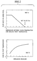
- Fig. 2 is a graph for explaining contents for controlling a fuel cell system of this embodiment.
- Fig. 3 is a flowchart showing procedures for controlling the fuel cell system of this embodiment.
- a fuel cell system 1 in this embodiment comprises a fuel tank 11 for storing fuel; an evaporator 12 for evaporating the fuel to generate fuel gas; a reforming reactor 13 for generating reforming gas containing hydrogen from the fuel gas; a combustor 14 for burning either the fuel or the reforming gas to supply heat to the evaporator 12; and a fuel cell portion 15 generating electricity by use of the hydrogen contained in the reforming gas that has been generated by the reforming reactor 13.
- the fuel cell system 1 further comprises a carbon monoxide remover 16 for removing carbon monoxide in the reforming gas generated by the reforming reactor 13 and a compressor 17 for supplying air as oxidizing agent to the reforming reactor 13, the fuel cell portion 15 and the carbon monoxide remover 16, respectively.
- the fuel gas from the evaporator 12 and air from the compressor 17 are sent to the reforming reactor 13.
- hydrogen-rich reforming gas is generated by the following catalytic reaction of the methanol, the water and oxygen in the air.
- the reaction represented by the equation (1) is a vapor reforming reaction (endothermic reaction)
- the reaction represented by the equation (2) is a partial oxidation reaction (exothermic reaction) of the methanol.
- the vapor reforming reaction of the equation (1) progresses step-by-step as shown by the following equations (3) and (4).
- the reaction represented by the equation (3) is a decomposition reaction (endothermic reaction) of the methanol
- the reaction represented by the equation (4) is a shift reaction (exothermic reaction) of carbon monoxide.
- the reforming reactor 13 of this embodiment is a heat insulation type reactor operated under an autothermal condition in which heat evolution and heat absorption are balanced in these equations.
- the following secondary reactions further occur along with the above reactions.
- the temperature of the reforming reactor 13 in motion ranges from 300 °C to 600 °C, and reforming gas containing carbon monoxide in order of several percentages is obtained by a thermodynamic chemical equilibrium.
- carbon monoxide damages a fuel electrode catalyst formed of platinum or the like, of a solid polymer fuel cell 15, and considerably lowers its activity.
- a carbon monoxide remover 16 is provided between the reforming reactor 13 and the fuel cell 15, and the reforming gas is supplied to the fuel cell 15 after carbon monoxide is reduced therefrom to several ten to 100 ppm.
- the reforming gas containing carbon monoxide in order of several percentages is sent to the carbon monoxide remover 16, and the carbon monoxide of the reforming gas is reduced by catalyst promoting the shift reaction represented by the equation (4).
- the operation temperature of the carbon monoxide remover 16 at this time ranges from 200 °C to 300 °C, and the reforming gas containing carbon monoxide in order of several tenth of percentage is obtained by thermodynamic chemical equilibrium.
- a reaction portion of the carbon monoxide remover 16 which performs the reactions represented by the equations (7) and (8) is cooled by air, LLC, oil or the like. An illustration of the reaction portion of the carbon monoxide remover 16 is omitted.
- the reforming gas in which the carbon monoxide is reduced to an extremely low level concentration and air from the compressor 17 are sent to fuel and air electrodes of the fuel cell 15, and electricity generation is performed.
- reference numeral 19 denotes a temperature sensor for measuring the temperature of the fuel gas which has passed through the evaporator 12, and an output of the temperature sensor 19 is transmitted to a controller (flow rate control portion) 30 to be described later.
- reference numerals 20 and 21 denote flow rate regulating valves for regulating the flow rate of air sent to the reforming reactor 13, the carbon monoxide remover 16 and the fuel cell 15 from the compressor 17, and the flow rate regulating valves 20 and 21 are feedback-controlled based on measurement values by the flow rate sensors 22 and 23 provided in respective supply systems.
- the reforming gas that has been used for electricity generation and in which hydrogen partially remains is also sent to the combustor 14.
- the air which has been used for the electricity generation and in which oxygen partially remains is sent to the burner 14.
- the reforming gas and the air sent to the burner 14 are burnt in the combustor 14.
- High temperature exhaust obtained in the combustor 14 is sent to the evaporator 12, and recycled as energy for allowing the methanol and the water to evaporate.
- reference numerals 24 and 25 denote pressure sensors for measuring the pressure of respective exhaust systems of the air electrode and the fuel electrode in the fuel cell 15, and reference numerals 26 and 27 denote flow rate regulating valves for regulating flow rates of the respective exhaust systems of the air electrode and the fuel electrode.
- quantities of the fuel supplied to the evaporator 12 and the combustor 14 also change, and the operation pressures of the evaporator 12 and the reforming reactor 13 change accordingly.
- a relation as shown in the map B of Fig. 2 exists between a boiling point temperature and the operation pressure.
- the operation pressure of the evaporator 12 can be obtained by a pressure loss from the evaporator 12 to the solid polymer type fuel cell 15 and the operation pressure of the solid polymer type fuel cell 15. Therefore, by obtaining the operation pressure of the evaporator 12 from the pressure sensor 25, the boiling point temperature Tbp of the fuel supplied from the fuel tank 11 can be estimated by a calculation.
- a boiling point temperature estimator 29 shown in Fig. 1 estimates by a calculation the boiling point temperature Tbp by use of the output value from the pressure sensor 25 and the map B shown in Fig. 2.
- the vapor temperature Tvap is never lower than the boiling point temperature Tbp. Specifically, when the vapor temperature Tvap is lower than the boiling point temperature Tbp, no vapor is generated. When the vapor temperature Tvap is equal to the boiling point temperature Tbp, a liquid phase and a vapor phase coexist. Moreover, when the difference between the vapor temperature Tvap and the boiling point temperature Tbp is large, it can be regarded that an amount of heat enough to obtain sufficient fuel gas for electricity generation at the solid polymer type fuel cell 15 is supplied to the evaporator 12. However, as the difference between the vapor temperature and the boiling point temperature becomes smaller, it can be regarded that an amount of heat at the evaporator 12 is decreased.
- a predetermined temperature difference Tcrt which is a critical value of the difference between the vapor temperature Tvap and the boiling point temperature Tbp is set in advance, an amount of heat is enough when a value obtained by subtracting the boiling point temperature Tbp from the vapor temperature Tvap is larger than the predetermined temperature difference Tcrt, and no additional fuel to the combustor 14 will not be supplied.
- a controller (a flow rate control portion) 30 shown in Fig. 1 calculates the necessary amount of heat for the evaporator 12 by using the boiling point temperature Tbp estimated by the above-described boiling point estimator 29 and the vapor temperature Tvap measured by the temperature sensor 19, and decides whether the amount of heat of the evaporator 12 is short or not.
- the controller 30 outputs a decision result to a pump 28 for supplying the fuel from the fuel tank 11 to the combustor 14.
- the temperature difference Tcrt is set so that a margin is provided between the amount of heat supplied to the evaporator 12 from the combustor 14 and the amount of heat of the evaporator 12 supplied to obtain the fuel gas which is required by the solid polymer type fuel cell 15 to generate sufficient electricity. Accordingly, it is possible to prevent the solid polymer type fuel cell 15 from stopping its operation due to a decrease of the supply amount of the fuel gas because of lack in the amount of heat of the evaporator 12. At the same time, it is always possible to stably supply the fuel gas to the solid polymer type fuel cell 15 and to generate electricity.
- An operation pressure of the fuel cell 15 is first read from the pressure sensor 25 in the step 1, and an operation pressure of the evaporator 12 is obtained based on the operation pressure of the fuel cell 15 and a pressure loss from the evaporator 12 to the solid polymer type fuel cell 15, which is a known value.
- the boiling point temperature Tbp of the fuel is estimated by a calculation, based on the operation pressure of the evaporator 12 obtained in the step 1 and the map B of Fig. 2.
- the calculation processing until the step 2 is executed by the boiling temperature estimator 29 shown in Fig. 1.
- the actual vapor temperature Tvap measured by the temperature sensor 19 is read, and the difference (Tvap - Tbp) between the vapor temperature Tvap and the boiling point temperature Tbp obtained in the step 2 is compared with the predetermined temperature difference Tcrt in the next step 4. Then, if Tvap - Tbp > Tcrt is satisfied, it is regarded that the amount of heat supplied to the evaporator 12 is enough, and the procedure returns to the step 1.
- the fuel supplied to the combustor 14 increases, and a large amount of heat generated is transmitted to the evaporator 12. Accordingly, the vapor temperature Tvap elevates, and the flow rate of the vaporized fuel increases. Therefore, it is possible to supply gas to the reforming reactor 13 so that electric power can be stably supplied in the fuel cell 15 portion.
- the fuel cell system 1 for use in the moving body having a structure that the reforming gas from the reforming reactor 13 into the fuel cell portion 15 is allowed to pass though the carbon monoxide remover 16, and supplied to the fuel cell 15 after reducing the carbon monoxide concentration.
- a structure of the carbon monoxide remover 16 is not particularly limited, and the carbon monoxide remover 16 may be applied to a fuel cell system having a structure that a hydrogen separation film is fitted in the downstream of the reforming reactor 13, and pure hydrogen separated thereby is used in the fuel cell 15 while the residual gas is sent to the combustor 14.
- a structure of the fuel cell system may be adopted, in which a pressure sensor is fitted between the evaporator 12 and the reforming reactor 13, and a signal of the operation pressure of the evaporator 12 is directly transmitted to the controller (the flow rate control portion) 30.
- a temperature sensor and a pressure sensor are fitted in the reforming reactor 13, and signals from the temperature sensor and the pressure sensor may be transmitted to the controller (the flow rate control portion) 30 to control the flow rate of the fuel supplied to the combustor 14 by the pump 28.
- a structure may be adopted, whereas another controller 31 and another pump 18 are provided as shown in Fig. 1, the flow rate of the fuel flowing into the evaporator 12 is controlled, and the fuel is stably supplied to the reforming reactor 13.
- the following structure may be adopted. Specifically, the flow rate of the fuel gas supplied from the evaporator 12 to the reforming reactor 13 is measured, and a surplus heat amount in the evaporator 12 is obtained based on the difference between the temperature of the evaporator and the boiling point temperature, together with the above-described flow rate of the fuel gas. Then, based on the surplus heat amount, the amount of the fuel supplied to the combustor 14 is controlled, and the amount of heat supplied from the combustor 14 is adjusted.
Landscapes
- Life Sciences & Earth Sciences (AREA)
- Engineering & Computer Science (AREA)
- Manufacturing & Machinery (AREA)
- Sustainable Development (AREA)
- Sustainable Energy (AREA)
- Chemical & Material Sciences (AREA)
- Chemical Kinetics & Catalysis (AREA)
- Electrochemistry (AREA)
- General Chemical & Material Sciences (AREA)
- Fuel Cell (AREA)
Claims (3)
- Système de pile à combustible, comprenant :un réservoir de combustible (11) pour stocker du combustible ;un évaporateur (12) pour faire évaporer ledit combustible afin de générer du gaz combustible ;un réacteur de reformage (13) pour générer du gaz de reformage contenant de l'hydrogène provenant dudit gaz combustible ;une chambre de combustion (14) pour brûler l'un quelconque dudit combustible et dudit gaz de reformage afin de fournir de la chaleur audit évaporateur (12) ;une partie de pile à combustible (15) pour générer de l'électricité par l'utilisation dudit hydrogène contenu dans ledit gaz de reformage dans ledit réacteur de reformage (13) ;un capteur de pression (25) pour estimer une pression opératoire dudit évaporateur (12) ;une partie de mesure de température de vapeur (19) pour mesurer une température de vapeur (Tvap) du gaz combustible dans ledit évaporateur (12) ; etune partie de commande de débit (30) pour commander un débit de l'un quelconque du combustible et du gaz de reformage brûlés dans ladite chambre de combustion (14) ;caractérisé par
une partie d'estimation de température de point d'ébullition (29) pour estimer une température de point d'ébullition (Tbp) dudit combustible dans ledit évaporateur (12) sur la base de la pression opératoire dudit évaporateur (12), dans lequel la partie de commande de débit (30) est adaptée pour augmenter le débit de l'un quelconque du combustible et du gaz de reformage brûlés dans ladite chambre de combustion (14) lorsqu'une valeur obtenue en soustrayant ladite température de point d'ébullition (Tbp) de ladite température de vapeur (Tvap) descend au-dessous d'une valeur prédéterminée (Tcrt). - Système de pile à combustible selon la revendication 1, caractérisé par
des moyens de fourniture (26, 27) pour fournir le gaz de reformage à ladite chambre de combustion (14), le gaz de reformage étant excédentaire dans ladite partie de pile à combustible (15), et pour y brûler le gaz de reformage, dans lequel
lorsque la valeur obtenue en soustrayant ladite température de point d'ébullition (Tbp) de ladite température de vapeur (Tvap) descend au-dessous de la valeur prédéterminée (Tcrt), la puissance électrique prélevée sur ladite partie de pile à combustible (15) est réduite pour augmenter une quantité de chaleur générée dans ladite chambre de combustion (14). - Procédé de commande d'un système de pile à combustible comprenant un réservoir de combustible (11) pour stocker du combustible, un évaporateur (12) pour faire évaporer ledit combustible afin de générer du gaz combustible, un réacteur de reformage (13) pour générer du gaz de reformage contenant de l'hydrogène provenant dudit gaz combustible, une chambre de combustion (14) pour brûler l'un quelconque dudit combustible et dudit gaz de reformage afin de fournir de la chaleur audit évaporateur (12), une partie de pile à combustible (15) pour générer de l'électricité par l'utilisation dudit hydrogène contenu dans ledit gaz de reformage généré dans ledit réacteur de reformage (13), une partie de mesure de température de vapeur (19) pour mesurer une température de vapeur (Tvap) du gaz combustible dans ledit évaporateur (12) ; et une partie de commande de débit (30) pour commander un débit de l'un quelconque du combustible et du gaz de reformage brûlés dans ladite chambre de combustion (14), ledit procédé comprenant les étapes consistant à :mesurer une température de vapeur (Tvap) du gaz combustible dans ledit évaporateur (12), etestimer une pression opératoire dudit évaporateur (12),caractérisé par les étapes consistant à
estimer une température de point d'ébullition (Tbp) dudit combustible dans ledit évaporateur (12) sur la base d'une pression opératoire dudit évaporateur (12), et
augmenter un débit de l'un quelconque du combustible et du gaz de reformage brûlés dans ladite chambre de combustion (14) lorsqu'une valeur obtenue en soustrayant ladite température de point d'ébullition (Tbp) de ladite température de vapeur (Tvap) descend au-dessous d'une valeur prédéterminée (Tcrt).
Applications Claiming Priority (2)
| Application Number | Priority Date | Filing Date | Title |
|---|---|---|---|
| JP2000159593 | 2000-05-30 | ||
| JP2000159593A JP3702751B2 (ja) | 2000-05-30 | 2000-05-30 | 燃料電池システム |
Publications (3)
| Publication Number | Publication Date |
|---|---|
| EP1160902A2 EP1160902A2 (fr) | 2001-12-05 |
| EP1160902A3 EP1160902A3 (fr) | 2006-03-01 |
| EP1160902B1 true EP1160902B1 (fr) | 2007-09-12 |
Family
ID=18663894
Family Applications (1)
| Application Number | Title | Priority Date | Filing Date |
|---|---|---|---|
| EP01113017A Expired - Lifetime EP1160902B1 (fr) | 2000-05-30 | 2001-05-28 | Système de pile à combustible |
Country Status (4)
| Country | Link |
|---|---|
| US (1) | US6635371B2 (fr) |
| EP (1) | EP1160902B1 (fr) |
| JP (1) | JP3702751B2 (fr) |
| DE (1) | DE60130401T2 (fr) |
Families Citing this family (18)
| Publication number | Priority date | Publication date | Assignee | Title |
|---|---|---|---|---|
| US6899741B2 (en) * | 1999-12-21 | 2005-05-31 | Honda Giken Kogyo Kabushiki Kaisha | Fuel evaporator |
| JP3480451B2 (ja) | 2001-05-22 | 2003-12-22 | 日産自動車株式会社 | 燃料電池システム |
| JP3452051B2 (ja) * | 2001-05-25 | 2003-09-29 | 日産自動車株式会社 | 燃料電池システム |
| JP3480452B2 (ja) | 2001-05-25 | 2003-12-22 | 日産自動車株式会社 | 燃料電池システムおよびエネルギ供給システム |
| JP3979057B2 (ja) | 2001-10-16 | 2007-09-19 | 日産自動車株式会社 | 燃料電池システムの制御装置 |
| JP3820992B2 (ja) * | 2002-01-08 | 2006-09-13 | 日産自動車株式会社 | 燃料電池システム |
| JP3911467B2 (ja) * | 2002-09-25 | 2007-05-09 | 出光興産株式会社 | エネルギ供給システム |
| CA2503356A1 (fr) * | 2002-10-30 | 2004-05-21 | Nuvera Fuel Cells, Inc. | Procede et systeme de commande d'un ecoulement de fluide dans un systeme de traitement de combustible |
| US7807302B2 (en) * | 2004-01-27 | 2010-10-05 | Utc Power Corporation | Preventing fuel starvation of a fuel cell stack |
| JP5151035B2 (ja) * | 2006-02-03 | 2013-02-27 | 日産自動車株式会社 | 燃料電池システム |
| JP5044135B2 (ja) * | 2006-03-31 | 2012-10-10 | 大阪瓦斯株式会社 | 燃料電池発電装置 |
| JP4258559B2 (ja) | 2007-06-08 | 2009-04-30 | カシオ計算機株式会社 | 気化装置並びにそれを備える発電装置及び電子機器 |
| JP4478707B2 (ja) * | 2007-09-06 | 2010-06-09 | 本田技研工業株式会社 | 燃料電池車両 |
| JP2009206076A (ja) * | 2008-01-28 | 2009-09-10 | Canon Inc | 燃料電池セルおよび燃料電池スタック |
| CA2754153C (fr) * | 2009-03-18 | 2017-01-03 | Crown Equipment Corporation | Jauge de carburant pour vehicules industriels |
| JP5285790B2 (ja) * | 2012-03-02 | 2013-09-11 | 大阪瓦斯株式会社 | 燃料電池発電装置 |
| CA2926906C (fr) * | 2013-10-08 | 2019-03-05 | Nissan Motor Co., Ltd. | Systeme de pile a combustible |
| WO2019215931A1 (fr) * | 2018-05-11 | 2019-11-14 | 日産自動車株式会社 | Système de pile à combustible et procédé de commande de système de pile à combustible |
Family Cites Families (10)
| Publication number | Priority date | Publication date | Assignee | Title |
|---|---|---|---|---|
| JPH09315801A (ja) * | 1996-03-26 | 1997-12-09 | Toyota Motor Corp | 燃料改質方法と燃料改質装置ならびに該燃料改質装置を備えた燃料電池システム |
| JPH10106607A (ja) | 1996-10-02 | 1998-04-24 | Shipbuild Res Assoc Japan | 固体高分子電解質型燃料電池発電装置 |
| DE19755813C2 (de) * | 1997-12-16 | 2000-09-14 | Dbb Fuel Cell Engines Gmbh | Verfahren zum Betrieb einer Wasserdampfreformierungsanlage, damit betreibbare Reformierungsanlage und Brennstoffzellensystem-Betriebsverfahren |
| US6630109B2 (en) * | 1998-07-16 | 2003-10-07 | Toyota Jidosha Kabushiki Kaisha | Control apparatus for reformer and method of controlling reformer using control apparatus |
| JP2000119001A (ja) * | 1998-10-13 | 2000-04-25 | Toyota Motor Corp | 水素生成装置 |
| JP4147659B2 (ja) * | 1998-12-24 | 2008-09-10 | トヨタ自動車株式会社 | 改質器の制御装置 |
| JP4100533B2 (ja) * | 1999-05-06 | 2008-06-11 | 日産自動車株式会社 | 燃料電池車における排水素燃焼器の温度制御装置 |
| JP4253920B2 (ja) * | 1999-05-06 | 2009-04-15 | 日産自動車株式会社 | 燃料電池自動車の電力配分制御装置 |
| JP3508094B2 (ja) * | 1999-06-15 | 2004-03-22 | 本田技研工業株式会社 | 燃料電池システムにおける液体燃料の蒸発制御方法 |
| JP3452051B2 (ja) * | 2001-05-25 | 2003-09-29 | 日産自動車株式会社 | 燃料電池システム |
-
2000
- 2000-05-30 JP JP2000159593A patent/JP3702751B2/ja not_active Expired - Fee Related
-
2001
- 2001-05-23 US US09/862,344 patent/US6635371B2/en not_active Expired - Fee Related
- 2001-05-28 EP EP01113017A patent/EP1160902B1/fr not_active Expired - Lifetime
- 2001-05-28 DE DE60130401T patent/DE60130401T2/de not_active Expired - Fee Related
Also Published As
| Publication number | Publication date |
|---|---|
| US20020001741A1 (en) | 2002-01-03 |
| US6635371B2 (en) | 2003-10-21 |
| EP1160902A2 (fr) | 2001-12-05 |
| EP1160902A3 (fr) | 2006-03-01 |
| DE60130401T2 (de) | 2008-01-03 |
| JP3702751B2 (ja) | 2005-10-05 |
| JP2001338665A (ja) | 2001-12-07 |
| DE60130401D1 (de) | 2007-10-25 |
Similar Documents
| Publication | Publication Date | Title |
|---|---|---|
| KR100466381B1 (ko) | 연료 개질 시스템 | |
| US6635371B2 (en) | Fuel cell system | |
| JP4105758B2 (ja) | 燃料電池システム | |
| JP5446184B2 (ja) | 発電システム及び発電システムの制御装置 | |
| KR100458082B1 (ko) | 이동체용 연료전지 시스템 및 그 제어 방법 | |
| JP2000053403A (ja) | 改質器の制御装置 | |
| US6752968B2 (en) | Reformer controlling apparatus | |
| US6630109B2 (en) | Control apparatus for reformer and method of controlling reformer using control apparatus | |
| US6602628B2 (en) | Control system for fuel cell | |
| US6797418B1 (en) | Fuel processor for fuel cell | |
| EP2835344B1 (fr) | Dispositif de génération d'hydrogène, procédé de fonctionnement et système de pile à combustible | |
| US6607855B2 (en) | Control system for fuel cell | |
| JP5379353B2 (ja) | 燃料電池装置における改質器の温度制御システム | |
| JP4357306B2 (ja) | 燃料改質装置および燃料電池システム | |
| JPH09161832A (ja) | 燃料電池発電装置とその運転方法及び運転制御方法 | |
| JP4610097B2 (ja) | 燃料改質システム | |
| US20100112392A1 (en) | Method for regenerating a reformer | |
| JP4476581B2 (ja) | 燃料電池発電システムとその燃料電池発電システムの制御法とその制御法を実現する制御プログラムとその制御プログラムを記録した記録媒体 | |
| JP2014047083A (ja) | 水素含有ガス生成装置及び水素含有ガス生成量調節方法 | |
| US20050129994A1 (en) | Determination of the lambda value of reformate | |
| JPH0547399A (ja) | 燃料電池発電システムの改質装置の温度制御方法及びその装置 | |
| JP4752348B2 (ja) | 水素燃料供給システム | |
| JP5592760B2 (ja) | 燃料電池発電システム | |
| JP4888415B2 (ja) | 燃料電池用改質装置の運転制御方法 | |
| JP2000178001A (ja) | 改質器の制御装置 |
Legal Events
| Date | Code | Title | Description |
|---|---|---|---|
| PUAI | Public reference made under article 153(3) epc to a published international application that has entered the european phase |
Free format text: ORIGINAL CODE: 0009012 |
|
| 17P | Request for examination filed |
Effective date: 20010528 |
|
| AK | Designated contracting states |
Kind code of ref document: A2 Designated state(s): AT BE CH CY DE DK ES FI FR GB GR IE IT LI LU MC NL PT SE TR |
|
| AX | Request for extension of the european patent |
Free format text: AL;LT;LV;MK;RO;SI |
|
| PUAL | Search report despatched |
Free format text: ORIGINAL CODE: 0009013 |
|
| AK | Designated contracting states |
Kind code of ref document: A3 Designated state(s): AT BE CH CY DE DK ES FI FR GB GR IE IT LI LU MC NL PT SE TR |
|
| AX | Request for extension of the european patent |
Extension state: AL LT LV MK RO SI |
|
| RIC1 | Information provided on ipc code assigned before grant |
Ipc: H01M 8/06 20060101AFI20011003BHEP Ipc: H01M 8/04 20060101ALI20060110BHEP |
|
| 17Q | First examination report despatched |
Effective date: 20060830 |
|
| AKX | Designation fees paid |
Designated state(s): DE FR GB |
|
| GRAP | Despatch of communication of intention to grant a patent |
Free format text: ORIGINAL CODE: EPIDOSNIGR1 |
|
| GRAS | Grant fee paid |
Free format text: ORIGINAL CODE: EPIDOSNIGR3 |
|
| GRAA | (expected) grant |
Free format text: ORIGINAL CODE: 0009210 |
|
| AK | Designated contracting states |
Kind code of ref document: B1 Designated state(s): DE FR GB |
|
| REG | Reference to a national code |
Ref country code: GB Ref legal event code: FG4D |
|
| REF | Corresponds to: |
Ref document number: 60130401 Country of ref document: DE Date of ref document: 20071025 Kind code of ref document: P |
|
| ET | Fr: translation filed | ||
| PLBE | No opposition filed within time limit |
Free format text: ORIGINAL CODE: 0009261 |
|
| STAA | Information on the status of an ep patent application or granted ep patent |
Free format text: STATUS: NO OPPOSITION FILED WITHIN TIME LIMIT |
|
| 26N | No opposition filed |
Effective date: 20080613 |
|
| PGFP | Annual fee paid to national office [announced via postgrant information from national office to epo] |
Ref country code: DE Payment date: 20090527 Year of fee payment: 9 Ref country code: FR Payment date: 20090515 Year of fee payment: 9 |
|
| PGFP | Annual fee paid to national office [announced via postgrant information from national office to epo] |
Ref country code: GB Payment date: 20100329 Year of fee payment: 10 |
|
| REG | Reference to a national code |
Ref country code: FR Ref legal event code: ST Effective date: 20110131 |
|
| PG25 | Lapsed in a contracting state [announced via postgrant information from national office to epo] |
Ref country code: DE Free format text: LAPSE BECAUSE OF NON-PAYMENT OF DUE FEES Effective date: 20101201 |
|
| PG25 | Lapsed in a contracting state [announced via postgrant information from national office to epo] |
Ref country code: FR Free format text: LAPSE BECAUSE OF NON-PAYMENT OF DUE FEES Effective date: 20100531 |
|
| GBPC | Gb: european patent ceased through non-payment of renewal fee |
Effective date: 20110528 |
|
| PG25 | Lapsed in a contracting state [announced via postgrant information from national office to epo] |
Ref country code: GB Free format text: LAPSE BECAUSE OF NON-PAYMENT OF DUE FEES Effective date: 20110528 |