EP1160925B1 - Contact électrique - Google Patents
Contact électrique Download PDFInfo
- Publication number
- EP1160925B1 EP1160925B1 EP01109647A EP01109647A EP1160925B1 EP 1160925 B1 EP1160925 B1 EP 1160925B1 EP 01109647 A EP01109647 A EP 01109647A EP 01109647 A EP01109647 A EP 01109647A EP 1160925 B1 EP1160925 B1 EP 1160925B1
- Authority
- EP
- European Patent Office
- Prior art keywords
- zone
- plug contact
- deformation
- electrical plug
- plug
- Prior art date
- Legal status (The legal status is an assumption and is not a legal conclusion. Google has not performed a legal analysis and makes no representation as to the accuracy of the status listed.)
- Expired - Lifetime
Links
- 239000000463 material Substances 0.000 claims description 26
- 238000003780 insertion Methods 0.000 claims description 16
- 230000037431 insertion Effects 0.000 claims description 16
- 210000002105 tongue Anatomy 0.000 claims description 14
- 239000011248 coating agent Substances 0.000 claims description 7
- 238000000576 coating method Methods 0.000 claims description 7
- 229910052782 aluminium Inorganic materials 0.000 claims description 5
- XAGFODPZIPBFFR-UHFFFAOYSA-N aluminium Chemical compound [Al] XAGFODPZIPBFFR-UHFFFAOYSA-N 0.000 claims description 5
- 230000002829 reductive effect Effects 0.000 claims description 4
- 230000036961 partial effect Effects 0.000 claims description 3
- 238000007765 extrusion coating Methods 0.000 claims description 2
- 239000004411 aluminium Substances 0.000 claims 1
- 230000033001 locomotion Effects 0.000 description 12
- 230000008859 change Effects 0.000 description 7
- 238000000034 method Methods 0.000 description 7
- 230000008901 benefit Effects 0.000 description 6
- 238000005260 corrosion Methods 0.000 description 5
- 230000007797 corrosion Effects 0.000 description 5
- 210000002414 leg Anatomy 0.000 description 5
- 230000009471 action Effects 0.000 description 4
- 238000004519 manufacturing process Methods 0.000 description 4
- 238000005538 encapsulation Methods 0.000 description 3
- 230000000670 limiting effect Effects 0.000 description 3
- 230000013011 mating Effects 0.000 description 3
- RYGMFSIKBFXOCR-UHFFFAOYSA-N Copper Chemical compound [Cu] RYGMFSIKBFXOCR-UHFFFAOYSA-N 0.000 description 2
- 238000005452 bending Methods 0.000 description 2
- 230000009286 beneficial effect Effects 0.000 description 2
- 229910052790 beryllium Inorganic materials 0.000 description 2
- ATBAMAFKBVZNFJ-UHFFFAOYSA-N beryllium atom Chemical compound [Be] ATBAMAFKBVZNFJ-UHFFFAOYSA-N 0.000 description 2
- 238000005266 casting Methods 0.000 description 2
- 238000004140 cleaning Methods 0.000 description 2
- 229910052802 copper Inorganic materials 0.000 description 2
- 239000010949 copper Substances 0.000 description 2
- KUNSUQLRTQLHQQ-UHFFFAOYSA-N copper tin Chemical compound [Cu].[Sn] KUNSUQLRTQLHQQ-UHFFFAOYSA-N 0.000 description 2
- 238000011161 development Methods 0.000 description 2
- 230000018109 developmental process Effects 0.000 description 2
- 238000005516 engineering process Methods 0.000 description 2
- 238000000465 moulding Methods 0.000 description 2
- 230000008569 process Effects 0.000 description 2
- 230000009467 reduction Effects 0.000 description 2
- 238000010521 absorption reaction Methods 0.000 description 1
- 230000004308 accommodation Effects 0.000 description 1
- 238000009412 basement excavation Methods 0.000 description 1
- 150000001875 compounds Chemical class 0.000 description 1
- 239000004020 conductor Substances 0.000 description 1
- 230000001627 detrimental effect Effects 0.000 description 1
- 238000004049 embossing Methods 0.000 description 1
- 230000002349 favourable effect Effects 0.000 description 1
- 238000010438 heat treatment Methods 0.000 description 1
- 238000009434 installation Methods 0.000 description 1
- 229910052751 metal Inorganic materials 0.000 description 1
- 239000002184 metal Substances 0.000 description 1
- 230000003647 oxidation Effects 0.000 description 1
- 238000007254 oxidation reaction Methods 0.000 description 1
- TWNQGVIAIRXVLR-UHFFFAOYSA-N oxo(oxoalumanyloxy)alumane Chemical compound O=[Al]O[Al]=O TWNQGVIAIRXVLR-UHFFFAOYSA-N 0.000 description 1
- 230000002093 peripheral effect Effects 0.000 description 1
- OFNHPGDEEMZPFG-UHFFFAOYSA-N phosphanylidynenickel Chemical compound [P].[Ni] OFNHPGDEEMZPFG-UHFFFAOYSA-N 0.000 description 1
- 230000001681 protective effect Effects 0.000 description 1
- 238000004080 punching Methods 0.000 description 1
- 230000003716 rejuvenation Effects 0.000 description 1
- 238000007789 sealing Methods 0.000 description 1
- 238000000926 separation method Methods 0.000 description 1
- 238000007493 shaping process Methods 0.000 description 1
- 229910000679 solder Inorganic materials 0.000 description 1
- 238000009827 uniform distribution Methods 0.000 description 1
- 210000000689 upper leg Anatomy 0.000 description 1
- 238000010792 warming Methods 0.000 description 1
- 230000003313 weakening effect Effects 0.000 description 1
Images


Classifications
-
- H—ELECTRICITY
- H01—ELECTRIC ELEMENTS
- H01R—ELECTRICALLY-CONDUCTIVE CONNECTIONS; STRUCTURAL ASSOCIATIONS OF A PLURALITY OF MUTUALLY-INSULATED ELECTRICAL CONNECTING ELEMENTS; COUPLING DEVICES; CURRENT COLLECTORS
- H01R13/00—Details of coupling devices of the kinds covered by groups H01R12/70 or H01R24/00 - H01R33/00
- H01R13/02—Contact members
- H01R13/10—Sockets for co-operation with pins or blades
- H01R13/11—Resilient sockets
- H01R13/112—Resilient sockets forked sockets having two legs
-
- H—ELECTRICITY
- H01—ELECTRIC ELEMENTS
- H01R—ELECTRICALLY-CONDUCTIVE CONNECTIONS; STRUCTURAL ASSOCIATIONS OF A PLURALITY OF MUTUALLY-INSULATED ELECTRICAL CONNECTING ELEMENTS; COUPLING DEVICES; CURRENT COLLECTORS
- H01R13/00—Details of coupling devices of the kinds covered by groups H01R12/70 or H01R24/00 - H01R33/00
- H01R13/02—Contact members
- H01R13/10—Sockets for co-operation with pins or blades
- H01R13/14—Resiliently-mounted rigid sockets
Definitions
- the invention relates to an electrical plug contact for the electrical connection of the plug contact as Counterpart associated plug-in connection with a electrical component according to claim 1.
- Such electrical plug contacts are often in Used in applications where they are a relative are exposed to high vibration load, z. B. in motor vehicles. Since the connection principle in such Plug contacts on a clamping action between the plug contact and the plug connection is based, it can depending on the strength of the clamping force or caused thereby Frictional force between the plug connection and the Plug contact and the strength of the vibrations to one Relative movement between the plug connection and the Plug contact come. This relative movement leads to a unwanted wear and depending on the material selection also to a corrosion of plug contact and Plug connection due to friction.
- plug contact should therefore the previously described Avoid the problem of fretting or fretting corrosion if possible fulfill further requirements. So the plug contact should be small and compact build, simple and inexpensive and preferably be produced in one piece. Furthermore he should be used for the increasingly popular in automotive engineering Dickwrahtbonden be. Methods and devices for this type of connection technology are, for example from EP 0 794 847 B1 and EP 0 649 701 A1.
- EP 0 411 888 A2 discloses an electrical connector for connection to a plug known, with at least one electrically conductive pin, wherein the connector at least one electrically conductive receiving terminal and the receiving terminal has a contact area and has a solder tail electrically connected to the contact area.
- the known connector the goal is pursued to absorb an external force on the Contact area of the receiving terminal is waged in the direction in which a male pin terminal is inserted into the contact area of the female terminal.
- This known connector is due to produce its relatively complicated shaping arrangement and therefore relatively expensive. Furthermore, he is also not suitable for thick wire bonding.
- deformation resistance is in the following a material property meant in the essentially inversely proportional to the elasticity of the material behaves.
- the plug contact according to the invention can be particularly advantageous for connection of electromechanical components, z.
- electromechanical components As pressure sensors or solenoid valves, to an electronic control system be used.
- electromechanical components together with the control electronics in an electronic Control unit arranged. Due to the deformability of the plug contact can also be used during manufacturing and Assembly of the electronic control unit occurring tolerances be compensated.
- the entire mating zone in the one leg of the L-shaped Area arranged while the other leg acts as a known from the mechanics ago bending beam.
- the problem of fretting or fretting corrosion is in the inventive plug contact the ductility of the intermediate zone is reached, the one Movement of the insertion zone in relation to the connection zone in Plugging direction allowed to some extent, resulting in smaller Movements of the plug connection z. B. as a result of Vibrations are compensated.
- the shape change takes place at a defined point in the manner of a joint.
- a second deformation range provided with reduced strain resistance, such that the preferred direction of deformation of along the first and the second strain-changing regions arranged by parallel spatial axes are.
- This has opposite to a single strain range the advantage that a pivoting of the plug-in zone in a movement of the same due to vibrations can be better avoided.
- This can also be done Relative movements between the plug-in zone and the plug connection be better avoided across the direction of insertion.
- frictional forces between the plug zone and the walls of a plug-in contact holding device avoided or at least reduced become.
- connection zone at the same time also for mechanical attachment of the plug contact, so that for the mechanical attachment no special area or part of the plug contact must be provided. hereby in particular, the low-cost manufacturability and the compact design of the plug contact promoted.
- the first and / or the second deformation range have, as already explained, a lower deformation resistance on than the remaining areas of the intermediate zone.
- This can be achieved, for example be that the or the deformation ranges in the essentially constant material cross-section of a Be subjected to warming and thereby a higher Achieve elasticity.
- the lower deformation resistance by reducing the material cross section reached the intermediate zone.
- a small reduction in the material cross section leads, which has the advantage that the electrical resistance not unnecessary in the field of strain ranges is increased.
- the insertion zone has at least two receiving tongues for receiving the plug-in connection, whose external Contour when not plugged plug connection facing away from the intermediate zone Side of the plug zone tapers.
- This is opposite known plug contacts whose outer contours the plug-in zone are substantially parallel to each other, achieved the advantage that the same footprint the insertion force or the clamping force with which the Receptacles record the plug connection, increased becomes. As a result, the frictional force is increased, and it can be even better at fretting and fretting corrosion be avoided.
- the cross-sectional area of a receiving tongue at least in a partial region linear, preferably in the middle area of the receiving tongue.
- connection zone of the plug contact a bond area on, by means of bonding an electrical component can be connected is.
- inventive Plug contact readily for an application in the Dickdrahtbond connection technology used.
- the Plug contact is preferably made of the material copper beryllium or copper-tin. This occurs in The practice das.Problem that this material a Oxidation is subject to what is detrimental to the application the thick wire bonding technique is.
- the bonding area at least partially a coating of aluminum on. This allows the plug in contact better be used with the Dickdrahtbond technique, as an aluminum oxide layer for bonding is not is disadvantageous. It is also beneficial to the bond area immediately before bonding a laser cleaning to undergo. In this case, if necessary, too to dispense with the aluminum coating.
- the Connecting zone (4) in the bonding area (12) a galvanic applied bondable coating on.
- a galvanic applied bondable coating on is preferably nickel-phosphorus as a coating material used.
- a receiving device for the electrical Plug contact provided, which has holding means, which for receiving the connection zone of Plug contacts are suitable, such that the connection zone immovable relative to the receiving device is held.
- the plug contact relative be easily mounted and by molding the receiving device in the provided with the plug contact electrical device to be attached. Retains this the mating zone their mobility compared to the Connection zone, which as a result of immovable absorption immovable in the cradle the electrical device is arranged ..
- the manufacturing step of overmoulding makes a difference
- the mounting of the receiving device by molding on the one hand, by using a relatively hard one or inflexible material, preferably hard plastic, supported for the recording device, on the other hand by using a the inside of the cradle Protective labyrinth seal before overmoulding which gives a direct access to Umspritzmasse locked to the interior of the recording device.
- the receiving device Motion limiting means on which this mobility of the plug-in zone and / or the intermediate zone limit against the recording device.
- the invention consists of the recording device of two parts, wherein the dividing plane in one embodiment substantially perpendicular and in another embodiment in the substantially parallel to the spatial axis of the preferred Deformation direction of the first strain area is.
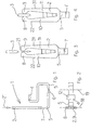
- the illustrated in FIGS. 1 to 3 electrical plug contact (1) is geometrically composed of an L-shaped Area (2, 5, 6, 7), to which an S-shaped or meandering region (4, 5, 6) connects.
- the Plug contact (1) has at its one end a complete in the one leg of the L-shaped area arranged plug-in zone (2), which is suitable, a to record their mating connector (3) assigned as a counterpart.
- the plug contact (1) a completely disposed in the S-shaped area Connection zone (4), which is for electrical connection the plug-in contact with an electrical component, z.
- the connection zone (4) a bonding pad (12), which is preferably using thick wire bonding with the electrical component is electrically connected.
- the bondpad (12) is in one preferred embodiment of the invention in one piece executed with the plug contact (1).
- the Bondpad (12) is preferably coated made of aluminum. Alternative to the aluminum coating or in addition to this, the bondpad (12) to undergo a laser cleaning.
- the plug contact (1) has an L-shaped and the S-shaped area overlapping intermediate zone (5), which is deformable to the plug zone (2) a certain Movability in plug-in direction (21) to compensate for To allow vibrations.
- the intermediate zone (5) is as elongated part formed and serves as a bending beam.
- a first (6) and a second (7) deformation range provided in Area of the intermediate zone (5) .
- the first Form change range (6) is shown in FIG. 1 in the horizontal Leg of the L-shaped area and the second Deformation area (7) in the vertical leg of the L-shaped area, i. the intermediate zone (5) is between the strain ranges (6, 7) angled substantially at right angles.
- the shape change regions (6, 7) have a smaller one Deformation resistance than the remaining areas of the Intermediate zone (5), which in a preferred embodiment the invention by a reduced material cross-section compared to the other areas of the Intermediate zone (5) is achieved.
- the deformation areas (6, 7) in particular provided a smaller material thickness than in the remaining areas of the intermediate zone (5).
- the shape change regions (6, 7) are preferred as Rejuvenation of the material of the intermediate zone (5) formed, z. B. by embossing. This is about a halving the thickness and the width of the material of the intermediate zone (5) provided.
- the shape changing portions (6, 7) may also by a local weakening of the material of the intermediate zone (5) with constant material cross section be realized, for. B. by heating. Also one Combining these methods is beneficial.
- connection zone (4) further serves for the mechanical Fixing the plug contact in a designated Receiving device, as with reference to FIG. 5 to 8 will be explained in more detail below.
- the plug-in zone (2) has two receiving tongues (8, 9), which serve to receive the plug connection (3).
- the plug-in zone (2) expanded under deformation of the receiving tongues (8, 9), so that the plug connection (3) by the spring action the material of the receiving tongues (8, 9) held becomes. Due to friction, the plug-in zone (2) opposite the plug connection (3) also in plug-in direction (21) forces immovable, as long as the not caused by stiction is overcome.
- the Friction force to choose higher than that due to the Deformation resistance of the deformation change regions (6, 7) resulting force for deformation of the intermediate zone (5).
- the frictional force is much higher to choose particularly advantageous about twice as high as the necessary force for the deformation. This can be done in advantageously a permanent friction between the plug connection (3) and the plug-in zone (2) avoided be, for. B. when vibration loads occur. By avoiding friction movements, the life becomes the connector increases because no fretting and no fretting corrosion occur.
- FIG. 3 tapers the outer contour (22, 31) of the receiving tongues with not plugged plug connection (3) in direction to the side facing away from the intermediate zone (5), d. H. in the present representation against the direction of insertion (21).
- the outer contours With inserted plug connection (3), as in the Fig. 4, the outer contours extend (22, 31) substantially parallel to each other, so that in a compact design, a high clamping force and consequently also a high frictional force for holding the Plug connection (3) is generated.
- the cross-sectional area a receiving tongue (8, 9) changes at least in a partial area (10, 11) of the respective Recording tongue (8, 9) substantially linear. hereby can be a uniform distribution of mechanical Voltages with inserted plug connection (3) achieved become.
- FIGS. 5 to 8 show the receiving device (13). for receiving the plug-in contact (1) with arranged therein Plug contact shown.
- the cradle consists of two half-shells (16, 17), which have a dividing plane which are substantially perpendicular to the spatial axis (19) of the preferred direction of deformation of the first strain area (6).
- the Half shells have a form-fitting interlocking Adjustment means (25) on which an exact assembly and adjustment the two half-shells (16, 17) to each other simplify.
- FIG. 5 it can be seen how the plug connection (1) in the one half shell (16) of the receiving device (13) is attached.
- the connection zone (4) becomes while positively received by holding means (23, 24) and of these immovable against the cradle (13) held.
- the plug-in zone (2) and the Intermediate zone (5) or at least the largest part thereof is to a limited extent movable relative to the receiving device (13), with the mobility of the intermediate zone (5) by movement limiting means (14, 15) is limited to a desired level.
- the mobility should, for example, a plastic Deformation of the intermediate zone (5) can be avoided.
- the plug contact (1) For complete installation of the plug contact (1) in the Recording device (13) is initially the plug contact (1) to insert in the one half shell (16), as in the Fig. 5 is shown, and then the second half-shell (17) on it. Then that can be done this way resulting unit mounted in an electronic device be, for example by encapsulation of the recording device (13) in the electronic device.
- the preferably half shells made of plastic (16, 17) serve here for all-around force support of the plug contact (1).
- the assembly process described above preferably runs fully automatically by means of a provided for this insertion machine.
- the labyrinth seal (28) is preferably as a peripheral to the half-shell (16) arranged Formed in the mounted state of the projection Receiving device (13) the edge of the half-shell (17) overlaps.
- a plurality of receiving devices (13) in the manner of a multiple connector stackable In a preferred embodiment of the invention a plurality of receiving devices (13) in the manner of a multiple connector stackable.
- Fig. 10 are two examples of the possibility of stringing together several receiving devices (13) according to Art a multiple connector shown in one Case with staggered receiving devices (13), in the other case in an aligned arrangement.
- the receiving devices (13) in a unified grid stackable.
- Figs. 11 to 14 are various embodiments the plug-in contact (1) according to the invention and its Connection by means of a bonding wire (26) to one as electrical component used electrical circuit board (20).
- Figs. 11 to 14 is the better illustration of the principle of a schematic and not true to scale representation used. The deformation zones (6, 7) are there with crosses shown.
- FIG. 11 corresponds to the embodiment of Fig. 1.
- Figs. 11 to 14 is in addition for each of the embodiments shown there an area (27) indicated in which the as Joint serving first deformation area (6) advantageous is to be arranged.
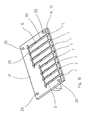
- FIGS. 15 to 17, that shown in FIG. 12 is shown Embodiment of the plug contact according to the invention (1) in connection with another embodiment the receiving device (13) as a three-page view shown, wherein in FIG. 16, the recording device (13) is shown in detail.
- the local Receiving device (13) has a parallel to the spatial axis (19) of the preferred direction of deformation of the first deformed region (6) Division level.
- the receiving device (13) consists also there from the parts (16, 17), which by means of positive interlocking adjusting means (25) simple way to mount each other exactly.
- the Adjusting means (25) correspond in their execution and Mode of action already explained adjusting.
- the embodiment of the recording device described here is (13) specifically for the inclusion of several Plug contacts (1) provided.
- the plug contacts Become as an initially common part of a Sheet metal punched and bent.
- the resulting Punching grid is then in the channel-like Material excavations, as a holding means (24, 29, 30), provided lower part (17) of the receiving device (13).
- the upper part (16) preferably has at the in the assembled state the channel-like Material lifts over opposite areas raised webs (not shown).
- FIG. 18 only one of the plug contacts (1) with the already explained Provided with reference numerals.
- plug contacts and receiving devices are preferably used for contacting arranged in an electronic control unit electromechanical components, eg. B. Pressure sensors or solenoid valves, with control electronics.
- electromechanical components eg. B. Pressure sensors or solenoid valves
- control electronics e.g. B. Pressure sensors or solenoid valves
- By applying the arrangements described above results in a small-sized, compact overall system, which has an easy to mount and again releasable connection between the electromechanical Components and the control electronics features.
- z. B. wired connectors or flexible conductor films is the invention Low cost, robust and thermal connector resilient.
Landscapes
- Coupling Device And Connection With Printed Circuit (AREA)
- Details Of Connecting Devices For Male And Female Coupling (AREA)
- Connector Housings Or Holding Contact Members (AREA)
- Connections Effected By Soldering, Adhesion, Or Permanent Deformation (AREA)
Claims (18)
- Connecteur électrique à enfichage (1) comportant une zone d'enfichage (2), qui convient pour recevoir un raccord enfichable (3) associé au contact à enfichage (1) en tant qu'élément antagoniste, une zone de liaison (4), qui sert à relier électriquement le contact à enfichage (1) à un composant électrique (20), ainsi qu'une zone intermédiaire (5) qui est disposée entre la zone d'enfichage (1) et la zone de liaison (4), dans lequela) le contact à enfichage (1) possède une zone en forme de L (2, 5, 6, 7) et l'ensemble de la zone d'enfichage (2) est disposée dans la partie en forme de L (2, 5, 6, 7),b) est déplaçable moyennant la déformation de la zone intermédiaire (5) par rapport à la zone de liaison (4) dans la direction d'enfichage (21), etc) la zone intermédiaire (5) comporte au moins une première zone de changement de forme (6), qui possède une résistance de changement de forme plus faible que les autres parties de la zone intermédiaire (5),d) la zone intermédiaire (5) possède une seconde zone de changement de forme (7) ayant une résistance réduite de changement de forme et dont la direction préférée de déformation est située le long d'un axial spatial (18) qui était seulement essentiellement parallèle à l'axe spatial (19) de la direction préférée de déformation de la première zone de changement de forme (6).
- Contact électrique à enfichage selon la revendication 1, caractérisé en ce que la zone intermédiaire (5) est coudée entre la première zone de changement de forme (6) et la seconde zone de changement de forme (7).
- Contact électrique à enfichage selon l'une des revendications précédentes, caractérisé par un coudage multiple au niveau de la zone de liaison (4) et/ou de la zone intermédiaire (5).
- Contact électrique à enfichage selon l'une des revendications précédentes, caractérisé en ce que la zone de liaison (4) sert à fixer mécaniquement le contact à enfichage (1).
- Contact électrique à enfichage selon l'une des revendications précédentes, caractérisé en ce que la zone d'enfichage (2) est appropriée pour loger un raccord enfichable (3) agencé sous la forme d'une languette de contact.
- Contact électrique à enfichage selon l'une des revendications précédentes, caractérisé en ce que la première zone de changement de forme (6) et/ou la seconde zone de changement de forme (7) possède une section transversale de matériau plus faible que les autres parties de la zone intermédiaire (5).
- Contact électrique à enfichage selon la revendication 6, caractérisé en ce que la première zone de changement de forme (6) et/ou la seconde zone de changement de forme (7) possède une épaisseur de matériau plus faible que les autres parties de la zone intermédiaire (5).
- Contact électrique à enfichage selon l'une des revendications précédentes, caractérisé en ce que la zone d'enfichage (2) comporte au moins deux languettes de réception (8, 9) servant à recevoir le raccord enfichable (3) et dont le contour extérieur (22, 31) se rétrécit, lorsque le raccord enfichable (3) n'est pas enfiché, en direction du côté de la zone d'enfichage (2), tourné à l'opposé de la zone intermédiaire (5).
- Contact électrique à enfichage selon l'une des revendications précédentes, caractérisé en ce que la surface en coupe transversale d'une languette de logement (8, 9) varie linéairement au moins sur une partie (10, 11) de la languette de réception (8, 9).
- Contact électrique à enfichage selon l'une des revendications précédentes, caractérisé en ce que le contact à enfichage (1) peut être fabriqué d'un seul tenant.
- Contact électrique à enfichage selon l'une des revendications précédentes, caractérisé en ce que la zone de liaison (4) comporte une zone de collage (12), à laquelle le composant électrique (20) peut être raccordé par collage.
- Contact électrique à enfichage selon la revendication 11, caractérisé en ce que la zone de liaison (4) comporte, dans la zone de collage (12), un revêtement d'aluminium.
- Contact électrique à enfichage selon la revendication 1, caractérisé en ce que la zone de liaison (4) comporte, dans la zone de collage (12), un revêtement déposé galvaniquement, pouvant être collé.
- Dispositif de réception pour un contact électrique à enfichage selon l'une des revendications précédentes, caractérisé en ce que le dispositif de réception (13) comporte des moyens de retenue (23, 24), qui conviennent pour recevoir, de préférence selon une liaison par formes complémentaires, la zone de liaison (4) du contact électrique à enfichage (1) de telle sorte que la zone de liaison (4) est retenue de façon immobile par rapport au dispositif de réception (13).
- Dispositif de réception selon la revendication 14, caractérisé en ce que le dispositif de réception (13) comporte des moyens de limitation de déplacement (14, 15), qui limitent la mobilité de la zone d'enfichage (2) et/ou la déformabilité de la zone intermédiaire (5) par rapport au dispositif de réception (13).
- Dispositif de réception selon l'une des revendications 14 ou 15, caractérisé en ce que le dispositif de réception (13) est constitué de deux parties (16, 17), le plan de séparation étant essentiellement perpendiculaire à l'axe spécial (19) de la direction préférée de déformation de la première zone de changement de forme (6).
- Dispositif de réception selon l'une des revendications 14 ou 15, caractérisé en ce que le dispositif de réception (13) est constitué de deux parties (16, 17), le plan de séparation étant essentiellement parallèle à l'axe spécial (19) de la direction préférée de déformation de la première zone de changement de forme (6).
- Dispositif de réception selon l'un des revendications 14 à 17, caractérisé en ce que le dispositif de réception (13) peut être fixé dans un appareil électrique par enrobage par injection.
Applications Claiming Priority (2)
| Application Number | Priority Date | Filing Date | Title |
|---|---|---|---|
| DE10027125A DE10027125A1 (de) | 2000-05-31 | 2000-05-31 | Elektrischer Steckkontakt |
| DE10027125 | 2000-05-31 |
Publications (3)
| Publication Number | Publication Date |
|---|---|
| EP1160925A2 EP1160925A2 (fr) | 2001-12-05 |
| EP1160925A3 EP1160925A3 (fr) | 2002-07-03 |
| EP1160925B1 true EP1160925B1 (fr) | 2004-07-07 |
Family
ID=7644312
Family Applications (1)
| Application Number | Title | Priority Date | Filing Date |
|---|---|---|---|
| EP01109647A Expired - Lifetime EP1160925B1 (fr) | 2000-05-31 | 2001-04-19 | Contact électrique |
Country Status (3)
| Country | Link |
|---|---|
| US (1) | US6537111B2 (fr) |
| EP (1) | EP1160925B1 (fr) |
| DE (2) | DE10027125A1 (fr) |
Families Citing this family (80)
| Publication number | Priority date | Publication date | Assignee | Title |
|---|---|---|---|---|
| US6869292B2 (en) * | 2001-07-31 | 2005-03-22 | Fci Americas Technology, Inc. | Modular mezzanine connector |
| US7390200B2 (en) | 2001-11-14 | 2008-06-24 | Fci Americas Technology, Inc. | High speed differential transmission structures without grounds |
| US20050196987A1 (en) * | 2001-11-14 | 2005-09-08 | Shuey Joseph B. | High density, low noise, high speed mezzanine connector |
| US6994569B2 (en) | 2001-11-14 | 2006-02-07 | Fci America Technology, Inc. | Electrical connectors having contacts that may be selectively designated as either signal or ground contacts |
| US6981883B2 (en) * | 2001-11-14 | 2006-01-03 | Fci Americas Technology, Inc. | Impedance control in electrical connectors |
| EP2451026A3 (fr) | 2001-11-14 | 2013-04-03 | Fci | Réduction de la diaphonie pour connecteurs électriques |
| DE10217099A1 (de) * | 2002-04-17 | 2003-11-06 | Delphi Tech Inc | Elektrische Anschlussvorrichtung |
| US7008250B2 (en) * | 2002-08-30 | 2006-03-07 | Fci Americas Technology, Inc. | Connector receptacle having a short beam and long wipe dual beam contact |
| US7270573B2 (en) * | 2002-08-30 | 2007-09-18 | Fci Americas Technology, Inc. | Electrical connector with load bearing features |
| US6899548B2 (en) * | 2002-08-30 | 2005-05-31 | Fci Americas Technology, Inc. | Electrical connector having a cored contact assembly |
| US20040147169A1 (en) | 2003-01-28 | 2004-07-29 | Allison Jeffrey W. | Power connector with safety feature |
| US7018246B2 (en) * | 2003-03-14 | 2006-03-28 | Fci Americas Technology, Inc. | Maintenance of uniform impedance profiles between adjacent contacts in high speed grid array connectors |
| US7083432B2 (en) * | 2003-08-06 | 2006-08-01 | Fci Americas Technology, Inc. | Retention member for connector system |
| US7524209B2 (en) | 2003-09-26 | 2009-04-28 | Fci Americas Technology, Inc. | Impedance mating interface for electrical connectors |
| US7517250B2 (en) * | 2003-09-26 | 2009-04-14 | Fci Americas Technology, Inc. | Impedance mating interface for electrical connectors |
| US7458839B2 (en) * | 2006-02-21 | 2008-12-02 | Fci Americas Technology, Inc. | Electrical connectors having power contacts with alignment and/or restraining features |
| CN101882718B (zh) | 2003-12-31 | 2012-11-21 | Fci公司 | 电源触头及包括电源触头的连接器 |
| JP4361429B2 (ja) * | 2004-06-29 | 2009-11-11 | 矢崎総業株式会社 | 直付けコネクタの嵌合構造 |
| US7242325B2 (en) * | 2004-08-02 | 2007-07-10 | Sony Corporation | Error correction compensating ones or zeros string suppression |
| US7160117B2 (en) * | 2004-08-13 | 2007-01-09 | Fci Americas Technology, Inc. | High speed, high signal integrity electrical connectors |
| US7214104B2 (en) * | 2004-09-14 | 2007-05-08 | Fci Americas Technology, Inc. | Ball grid array connector |
| US7281950B2 (en) * | 2004-09-29 | 2007-10-16 | Fci Americas Technology, Inc. | High speed connectors that minimize signal skew and crosstalk |
| DE102004048975A1 (de) * | 2004-10-07 | 2006-04-13 | Wabco Gmbh & Co.Ohg | Elektrischer Steckkontakt |
| DE102004050715B3 (de) * | 2004-10-19 | 2006-03-09 | Küster Automotive Door Systems GmbH | Kontaktelement zur elektrischen Kontaktierung zweier Anschlüsse |
| US7476108B2 (en) * | 2004-12-22 | 2009-01-13 | Fci Americas Technology, Inc. | Electrical power connectors with cooling features |
| US7226296B2 (en) * | 2004-12-23 | 2007-06-05 | Fci Americas Technology, Inc. | Ball grid array contacts with spring action |
| US7384289B2 (en) * | 2005-01-31 | 2008-06-10 | Fci Americas Technology, Inc. | Surface-mount connector |
| US7303427B2 (en) * | 2005-04-05 | 2007-12-04 | Fci Americas Technology, Inc. | Electrical connector with air-circulation features |
| US20060228912A1 (en) * | 2005-04-07 | 2006-10-12 | Fci Americas Technology, Inc. | Orthogonal backplane connector |
| US20060245137A1 (en) * | 2005-04-29 | 2006-11-02 | Fci Americas Technology, Inc. | Backplane connectors |
| US7396259B2 (en) * | 2005-06-29 | 2008-07-08 | Fci Americas Technology, Inc. | Electrical connector housing alignment feature |
| US7819708B2 (en) * | 2005-11-21 | 2010-10-26 | Fci Americas Technology, Inc. | Receptacle contact for improved mating characteristics |
| DE102006001876A1 (de) * | 2006-01-13 | 2007-11-08 | Siemens Ag | Bauteil mit einer elektrischen Flachbaugruppe |
| US7425145B2 (en) * | 2006-05-26 | 2008-09-16 | Fci Americas Technology, Inc. | Connectors and contacts for transmitting electrical power |
| US7726982B2 (en) | 2006-06-15 | 2010-06-01 | Fci Americas Technology, Inc. | Electrical connectors with air-circulation features |
| US7462924B2 (en) * | 2006-06-27 | 2008-12-09 | Fci Americas Technology, Inc. | Electrical connector with elongated ground contacts |
| US7500871B2 (en) * | 2006-08-21 | 2009-03-10 | Fci Americas Technology, Inc. | Electrical connector system with jogged contact tails |
| US7713088B2 (en) | 2006-10-05 | 2010-05-11 | Fci | Broadside-coupled signal pair configurations for electrical connectors |
| US7708569B2 (en) | 2006-10-30 | 2010-05-04 | Fci Americas Technology, Inc. | Broadside-coupled signal pair configurations for electrical connectors |
| US7497736B2 (en) * | 2006-12-19 | 2009-03-03 | Fci Americas Technology, Inc. | Shieldless, high-speed, low-cross-talk electrical connector |
| US20080203547A1 (en) * | 2007-02-26 | 2008-08-28 | Minich Steven E | Insert molded leadframe assembly |
| US7641500B2 (en) * | 2007-04-04 | 2010-01-05 | Fci Americas Technology, Inc. | Power cable connector system |
| US7905731B2 (en) * | 2007-05-21 | 2011-03-15 | Fci Americas Technology, Inc. | Electrical connector with stress-distribution features |
| US7811100B2 (en) * | 2007-07-13 | 2010-10-12 | Fci Americas Technology, Inc. | Electrical connector system having a continuous ground at the mating interface thereof |
| US7762857B2 (en) | 2007-10-01 | 2010-07-27 | Fci Americas Technology, Inc. | Power connectors with contact-retention features |
| US8764464B2 (en) * | 2008-02-29 | 2014-07-01 | Fci Americas Technology Llc | Cross talk reduction for high speed electrical connectors |
| US8062051B2 (en) * | 2008-07-29 | 2011-11-22 | Fci Americas Technology Llc | Electrical communication system having latching and strain relief features |
| US8545240B2 (en) | 2008-11-14 | 2013-10-01 | Molex Incorporated | Connector with terminals forming differential pairs |
| MY155071A (en) | 2008-12-12 | 2015-08-28 | Molex Inc | Resonance modifying connector |
| USD664096S1 (en) | 2009-01-16 | 2012-07-24 | Fci Americas Technology Llc | Vertical electrical connector |
| USD606497S1 (en) | 2009-01-16 | 2009-12-22 | Fci Americas Technology, Inc. | Vertical electrical connector |
| USD640637S1 (en) | 2009-01-16 | 2011-06-28 | Fci Americas Technology Llc | Vertical electrical connector |
| USD608293S1 (en) | 2009-01-16 | 2010-01-19 | Fci Americas Technology, Inc. | Vertical electrical connector |
| USD610548S1 (en) | 2009-01-16 | 2010-02-23 | Fci Americas Technology, Inc. | Right-angle electrical connector |
| USD606496S1 (en) | 2009-01-16 | 2009-12-22 | Fci Americas Technology, Inc. | Right-angle electrical connector |
| USD619099S1 (en) | 2009-01-30 | 2010-07-06 | Fci Americas Technology, Inc. | Electrical connector |
| US8323049B2 (en) * | 2009-01-30 | 2012-12-04 | Fci Americas Technology Llc | Electrical connector having power contacts |
| US9277649B2 (en) | 2009-02-26 | 2016-03-01 | Fci Americas Technology Llc | Cross talk reduction for high-speed electrical connectors |
| US8366485B2 (en) | 2009-03-19 | 2013-02-05 | Fci Americas Technology Llc | Electrical connector having ribbed ground plate |
| USD618181S1 (en) | 2009-04-03 | 2010-06-22 | Fci Americas Technology, Inc. | Asymmetrical electrical connector |
| USD618180S1 (en) | 2009-04-03 | 2010-06-22 | Fci Americas Technology, Inc. | Asymmetrical electrical connector |
| US8608510B2 (en) * | 2009-07-24 | 2013-12-17 | Fci Americas Technology Llc | Dual impedance electrical connector |
| US8267721B2 (en) * | 2009-10-28 | 2012-09-18 | Fci Americas Technology Llc | Electrical connector having ground plates and ground coupling bar |
| US8616919B2 (en) * | 2009-11-13 | 2013-12-31 | Fci Americas Technology Llc | Attachment system for electrical connector |
| CN102725919B (zh) * | 2009-12-30 | 2015-07-08 | Fci公司 | 具有阻抗调节肋的电连接器 |
| US9136634B2 (en) | 2010-09-03 | 2015-09-15 | Fci Americas Technology Llc | Low-cross-talk electrical connector |
| EP2624034A1 (fr) | 2012-01-31 | 2013-08-07 | Fci | Dispositif de couplage optique démontable |
| USD718253S1 (en) | 2012-04-13 | 2014-11-25 | Fci Americas Technology Llc | Electrical cable connector |
| USD727852S1 (en) | 2012-04-13 | 2015-04-28 | Fci Americas Technology Llc | Ground shield for a right angle electrical connector |
| US9257778B2 (en) | 2012-04-13 | 2016-02-09 | Fci Americas Technology | High speed electrical connector |
| US8944831B2 (en) | 2012-04-13 | 2015-02-03 | Fci Americas Technology Llc | Electrical connector having ribbed ground plate with engagement members |
| USD727268S1 (en) | 2012-04-13 | 2015-04-21 | Fci Americas Technology Llc | Vertical electrical connector |
| US9543703B2 (en) | 2012-07-11 | 2017-01-10 | Fci Americas Technology Llc | Electrical connector with reduced stack height |
| USD751507S1 (en) | 2012-07-11 | 2016-03-15 | Fci Americas Technology Llc | Electrical connector |
| JP2014063613A (ja) * | 2012-09-20 | 2014-04-10 | Mabuchi Motor Co Ltd | ターミナルの製造方法およびターミナル |
| USD745852S1 (en) | 2013-01-25 | 2015-12-22 | Fci Americas Technology Llc | Electrical connector |
| USD720698S1 (en) | 2013-03-15 | 2015-01-06 | Fci Americas Technology Llc | Electrical cable connector |
| USD825474S1 (en) * | 2016-04-25 | 2018-08-14 | Phoenix Contact Gmbh & Co. Kg | Electrical connector |
| DE102016008582A1 (de) | 2016-07-14 | 2018-01-18 | Wabco Gmbh | Kontaktelement und Kontaktvorrichtung für elektrische Steckverbindungen |
| USD1066263S1 (en) * | 2022-11-11 | 2025-03-11 | Tyco Electronics Amp Korea Co., Ltd. | Electrical terminal |
Family Cites Families (16)
| Publication number | Priority date | Publication date | Assignee | Title |
|---|---|---|---|---|
| DE1080650B (de) * | 1959-04-17 | 1960-04-28 | Geyer Fa Christian | Steckbuchse |
| US4303294A (en) * | 1980-03-17 | 1981-12-01 | Amp Incorporated | Compound spring contact |
| ATE49828T1 (de) * | 1983-11-08 | 1990-02-15 | Amp Inc | Steckverbinder mit flachen, ausgestanzten kontaktorganen. |
| GB2188497B (en) * | 1986-03-27 | 1990-11-07 | Yazaki Corp | Connector |
| DE8711110U1 (de) * | 1986-08-19 | 1987-12-17 | Feinmetall Gmbh, 7033 Herrenberg | Kontaktiervorrichtung |
| JPH0338769Y2 (fr) * | 1989-08-01 | 1991-08-15 | ||
| US5004426A (en) * | 1989-09-19 | 1991-04-02 | Teradyne, Inc. | Electrically connecting |
| JPH07109780B2 (ja) * | 1991-02-19 | 1995-11-22 | 山一電機株式会社 | 電気部品用ソケットにおけるコンタクト |
| DE4335468A1 (de) * | 1993-10-18 | 1995-04-20 | F&K Delvotec Bondtechnik Gmbh | Vorrichtung und Verfahren zum Drahtbonden |
| FR2719163A1 (fr) * | 1994-04-22 | 1995-10-27 | Amp France | Borne anti-corrosion par usure, destinée à recevoir une borne complémentaire. |
| DE4416888C1 (de) * | 1994-05-13 | 1995-06-01 | Neutrik Ag | Kontaktelement für elektrische Steckverbinder |
| DE4444388A1 (de) * | 1994-11-28 | 1996-05-30 | Atotech Deutschland Gmbh | Verfahren zum Bonden von Drähten auf oxidationsempfindlichen, lötbaren Metallsubstraten |
| US5564952A (en) * | 1994-12-22 | 1996-10-15 | The Whitaker Corporation | Electrical plug connector with blade receiving slots |
| JP3099111B2 (ja) * | 1996-05-31 | 2000-10-16 | モレックス インコーポレーテッド | リセプタクルコンタクトおよびリセプタクルコンタクトストリップ並びにリセプタクルコンタクトの製造方法 |
| US6116926A (en) * | 1999-04-21 | 2000-09-12 | Berg Technology, Inc. | Connector for electrical isolation in a condensed area |
| US6224432B1 (en) * | 1999-12-29 | 2001-05-01 | Berg Technology, Inc. | Electrical contact with orthogonal contact arms and offset contact areas |
-
2000
- 2000-05-31 DE DE10027125A patent/DE10027125A1/de not_active Withdrawn
-
2001
- 2001-04-19 DE DE50102780T patent/DE50102780D1/de not_active Expired - Lifetime
- 2001-04-19 EP EP01109647A patent/EP1160925B1/fr not_active Expired - Lifetime
- 2001-05-22 US US09/862,633 patent/US6537111B2/en not_active Expired - Lifetime
Also Published As
| Publication number | Publication date |
|---|---|
| EP1160925A2 (fr) | 2001-12-05 |
| EP1160925A3 (fr) | 2002-07-03 |
| DE50102780D1 (de) | 2004-08-12 |
| US6537111B2 (en) | 2003-03-25 |
| US20010049238A1 (en) | 2001-12-06 |
| DE10027125A1 (de) | 2001-12-06 |
Similar Documents
| Publication | Publication Date | Title |
|---|---|---|
| EP1160925B1 (fr) | Contact électrique | |
| DE69300865T2 (de) | Elektrischer verbinder mit blech als steckkontaktmaterial. | |
| DE60027611T2 (de) | Kabelverbinder mit gesteuerter Impedanz | |
| DE69921384T2 (de) | Leistungsverbinder | |
| EP2089936B1 (fr) | Connexion à borne guillotine et procédé pour connecter deux composants | |
| DE102015211002B4 (de) | Verbinder mit einem Verbindergehäuse und einem Verbinderanschluss | |
| EP1429423B1 (fr) | Connecteur électrique à fiche ayant un boîtier et un contact à courant fort | |
| DE112013005813T5 (de) | Weiblicher Anschluss | |
| DE69014915T2 (de) | Elektrischer Verbinder. | |
| WO2019080963A1 (fr) | Cadre de retenue pour un connecteur industriel | |
| EP1743402A1 (fr) | Broche pour liaison electrique sans etain comprenant une plaque conductrice, outil d'estampage et procede pour produire une liaison electrique sans etain | |
| EP3714514B1 (fr) | Connecteur enfichable | |
| DE102015211725B4 (de) | Verbinderanschluss und Verbinder hiermit | |
| DE69600844T2 (de) | Elektromotor-zusammenbau und elektrokontakt zur verwendung dafuer | |
| DE69902865T2 (de) | Leiterplattenoberflächenmontierbarer elektrischer Verbinder mit vorgespannten Kontakten | |
| WO2005028834A1 (fr) | Dispositif de positionnement conçu en particulier pour un papillon de moteur a combustion interne | |
| EP2105998B1 (fr) | Blindage de connecteur, système de connecteur et utilisation | |
| DE102010039747A1 (de) | Kontaktelement zur Kontaktierung eines Verbrauchers mit einem Steuergerät, Anordnung aus einem Verbraucher und einem Steuergerät, sowie Verfahren zur Montage einer solchen Anordnung | |
| LU101643B1 (de) | Steckkontaktelement, Direktsteckverbinder, Verfahren zur Herstellung eines Steckkontaktelementes und Verfahren zur Herstellung eines Direktsteckverbinders | |
| DE29608176U1 (de) | Zugfederanschluß für elektrische Leiter mit Anschlagrippen | |
| DE202010008456U1 (de) | Steckverbindung | |
| EP2219271B1 (fr) | Dispositif de connexion à fiche pour un composant électronique | |
| DE102024114161A1 (de) | Flachkontaktbuchse | |
| DE102004048059B3 (de) | Elektrisches Kontaktelement | |
| DE4136031C1 (en) | Double plug contact for car electric installation - consists of 2 terminal contact fins integral with strip conductor web |
Legal Events
| Date | Code | Title | Description |
|---|---|---|---|
| PUAI | Public reference made under article 153(3) epc to a published international application that has entered the european phase |
Free format text: ORIGINAL CODE: 0009012 |
|
| AK | Designated contracting states |
Kind code of ref document: A2 Designated state(s): AT BE CH CY DE DK ES FI FR GB GR IE IT LI LU MC NL PT SE TR |
|
| AX | Request for extension of the european patent |
Free format text: AL;LT;LV;MK;RO;SI |
|
| PUAL | Search report despatched |
Free format text: ORIGINAL CODE: 0009013 |
|
| AK | Designated contracting states |
Kind code of ref document: A3 Designated state(s): AT BE CH CY DE DK ES FI FR GB GR IE IT LI LU MC NL PT SE TR |
|
| AX | Request for extension of the european patent |
Free format text: AL;LT;LV;MK;RO;SI |
|
| RIC1 | Information provided on ipc code assigned before grant |
Free format text: 7H 01R 13/14 A, 7H 01R 13/11 B |
|
| 17P | Request for examination filed |
Effective date: 20030103 |
|
| AKX | Designation fees paid |
Designated state(s): DE FR GB IT SE |
|
| 17Q | First examination report despatched |
Effective date: 20030723 |
|
| GRAP | Despatch of communication of intention to grant a patent |
Free format text: ORIGINAL CODE: EPIDOSNIGR1 |
|
| GRAS | Grant fee paid |
Free format text: ORIGINAL CODE: EPIDOSNIGR3 |
|
| GRAA | (expected) grant |
Free format text: ORIGINAL CODE: 0009210 |
|
| AK | Designated contracting states |
Kind code of ref document: B1 Designated state(s): DE FR GB IT SE |
|
| REG | Reference to a national code |
Ref country code: GB Ref legal event code: FG4D Free format text: NOT ENGLISH |
|
| REG | Reference to a national code |
Ref country code: SE Ref legal event code: TRGR |
|
| REG | Reference to a national code |
Ref country code: IE Ref legal event code: FG4D Free format text: GERMAN |
|
| REF | Corresponds to: |
Ref document number: 50102780 Country of ref document: DE Date of ref document: 20040812 Kind code of ref document: P |
|
| GBT | Gb: translation of ep patent filed (gb section 77(6)(a)/1977) |
Effective date: 20041013 |
|
| REG | Reference to a national code |
Ref country code: IE Ref legal event code: FD4D |
|
| ET | Fr: translation filed | ||
| PLBE | No opposition filed within time limit |
Free format text: ORIGINAL CODE: 0009261 |
|
| STAA | Information on the status of an ep patent application or granted ep patent |
Free format text: STATUS: NO OPPOSITION FILED WITHIN TIME LIMIT |
|
| 26N | No opposition filed |
Effective date: 20050408 |
|
| REG | Reference to a national code |
Ref country code: FR Ref legal event code: PLFP Year of fee payment: 16 |
|
| REG | Reference to a national code |
Ref country code: FR Ref legal event code: PLFP Year of fee payment: 17 |
|
| REG | Reference to a national code |
Ref country code: FR Ref legal event code: PLFP Year of fee payment: 18 |
|
| PGFP | Annual fee paid to national office [announced via postgrant information from national office to epo] |
Ref country code: DE Payment date: 20200430 Year of fee payment: 20 Ref country code: FR Payment date: 20200421 Year of fee payment: 20 |
|
| PGFP | Annual fee paid to national office [announced via postgrant information from national office to epo] |
Ref country code: IT Payment date: 20200423 Year of fee payment: 20 Ref country code: GB Payment date: 20200423 Year of fee payment: 20 Ref country code: SE Payment date: 20200423 Year of fee payment: 20 |
|
| REG | Reference to a national code |
Ref country code: DE Ref legal event code: R071 Ref document number: 50102780 Country of ref document: DE |
|
| REG | Reference to a national code |
Ref country code: GB Ref legal event code: PE20 Expiry date: 20210418 |
|
| REG | Reference to a national code |
Ref country code: SE Ref legal event code: EUG |
|
| PG25 | Lapsed in a contracting state [announced via postgrant information from national office to epo] |
Ref country code: GB Free format text: LAPSE BECAUSE OF EXPIRATION OF PROTECTION Effective date: 20210418 |