EP1160948A1 - Teilbares, modulares und orientierbares Element für selbstausrichtende Kabelkanäle - Google Patents
Teilbares, modulares und orientierbares Element für selbstausrichtende Kabelkanäle Download PDFInfo
- Publication number
- EP1160948A1 EP1160948A1 EP01109063A EP01109063A EP1160948A1 EP 1160948 A1 EP1160948 A1 EP 1160948A1 EP 01109063 A EP01109063 A EP 01109063A EP 01109063 A EP01109063 A EP 01109063A EP 1160948 A1 EP1160948 A1 EP 1160948A1
- Authority
- EP
- European Patent Office
- Prior art keywords
- modular
- cavities
- modular element
- coaxial
- raceways
- Prior art date
- Legal status (The legal status is an assumption and is not a legal conclusion. Google has not performed a legal analysis and makes no representation as to the accuracy of the status listed.)
- Granted
Links
- 230000015572 biosynthetic process Effects 0.000 claims abstract description 10
- 230000008878 coupling Effects 0.000 claims abstract description 10
- 238000010168 coupling process Methods 0.000 claims abstract description 10
- 238000005859 coupling reaction Methods 0.000 claims abstract description 10
- 230000000295 complement effect Effects 0.000 claims description 13
- 230000002093 peripheral effect Effects 0.000 claims description 6
- 244000309464 bull Species 0.000 abstract 1
- 238000011161 development Methods 0.000 description 2
- 230000018109 developmental process Effects 0.000 description 2
- 238000012986 modification Methods 0.000 description 2
- 230000004048 modification Effects 0.000 description 2
- 239000003292 glue Substances 0.000 description 1
- 238000003780 insertion Methods 0.000 description 1
- 230000010355 oscillation Effects 0.000 description 1
- 230000000452 restraining effect Effects 0.000 description 1
Images

Classifications
-
- H—ELECTRICITY
- H02—GENERATION; CONVERSION OR DISTRIBUTION OF ELECTRIC POWER
- H02G—INSTALLATION OF ELECTRIC CABLES OR LINES, OR OF COMBINED OPTICAL AND ELECTRIC CABLES OR LINES
- H02G3/00—Installations of electric cables or lines or protective tubing therefor in or on buildings, equivalent structures or vehicles
- H02G3/02—Details
- H02G3/04—Protective tubing or conduits, e.g. cable ladders or cable troughs
- H02G3/0462—Tubings, i.e. having a closed section
- H02G3/0475—Tubings, i.e. having a closed section formed by a succession of articulated units
Definitions
- the present invention relates to a sectional, modular orientable element for fairlead raceways.
- the present invention relates to a sectional, modular and orientable element for the formation of single or multiple, rectilinear and/or curvilinear raceways for electric wires.
- Sectional elements for the formation of single or multiple raceways for electric wires are already known.
- sectional raceways are known that are formed by fixed peripheral supports, which must be tied to the surfaces by means of glues, screws or the like.
- the vertical feeders are located in correspondence of guide and support walls, and the variations in the wire ways, especially the orthogonal ones, are not guided in any way.
- Raceways for single or multiple wires are also known that are obtainable with coupling means fitted into one another. Also these coupling means, though being more functional than the fixed peripheral supports, require particular assembly contrivances and the use of specific accessories, such as orientation brackets, protection bases and the like, to compose the parts concerning the way variations of the wire, especially for orthogonal way variations.
- Object of this invention is to eliminate the above drawbacks.
- object of this invention is to provide a sectional, modular and orientable element such as to allow to realize single or multiple fairlead raceways with any way variations, even orthogonal.
- this object is achieved by a sectional, modular and oriental element having the features of the characterizing part of claim 1.
- the central bodies are sectional in a concatenated sense by means of the mutual fitting association of the peripheral hemispherical bulbs of the ones with the complementary cavities of the other ones.
- the individual modular elements are so aligned that the plurality of shaped arms form continuous channels wherein the wires are located.
- the bulbs are located at the end of linear extensions that allow the fit either in the outermost or the innermost cavity, so that the corresponding sequential concatenation of the modular elements allows to realize flexible and oriental couplings, to form parts of curved raceways intended for variations in the direction of the wires contained therein, or rigid linear couplings, to form parts of curved raceways intended for linearly oriented cables.
- the modular element of the present invention allows to realize rigid or flexible couplings, operating on the positioning of the hemispheric bulbs in the innermost or outermost cavities.
- the advantages achieved with the modular element of the present invention lie in that, depending on the more or less deep fitting of the hemispheric bulbs, the same type of elements is utilized for the formation of continuous ways, comprising linear or curved portions, without needing external accessories; for the formation of curvilinear raceways, the coupled modular elements are partly inclined.
- Wires of the same or a different configuration may be located in the sectional raceways.
- the modular elements ensure a rational and continuous formation of said raceways, independently on their development, their length and their orientation.
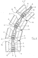
- the sectional, modular element of the present invention indicate by 1 as a whole, comprises a central body 2 having an end provided with a hemispheric bulb 3, and the opposite end provided with complementary sequential and coaxial cavities, 4, 5.
- the sequential and coaxial cavities 4, 5 are circumscribed by annular fitting edges 12 having a diameter slightly smaller that that of said cavities.
- Bulb 3 and the complementary cavities 4, 5 are coaxial with each other and with the central body 2.
- arms 6 From the central body 2 shaped arms 6 extend radially, distributed along its total or partial peripheral surface; said arms form channels 7, 7' having different forms and developments, suitable to engage therein wires 8 having different dimensions.
- Arms 6 are preferably fixed and integral with the central body 2, but, for particular applications, they may be movable, in which case body 2 is realized with longitudinal grooves, radial and shaped, for instance having a dovetail shape, wherein there are fitted the complementary inner ends of movable shaped arms 6, which develop for a length substantially equal to that of the same central body 2. Arms 6 may have different configurations, depending on the type of channels 7, 7' to be formed.
- the sequential coaxial cavities 4, 5 are obtained in the rear end 9 of the central body 2, while the hemispheric bulb 3 is located at the end of an extension 10 whose central body 2 is provided in correspondence of the opposite end.
- Said extension 10 is coaxial with respect to cavities 4, 5 and its length is proportional to the number of cavities and the depth of the innermost coaxial cavity 5.
- the central bodies 2 associate with each other in a concatenated alignment by means of the mutual fitting association of the hemispheric bulb 3 of the ones with one of the complementary axial cavities 4, 5 of the other ones. In such association also arms 6 are aligned, for the formation of the continuous channels 7, 7', wherein wires 8 are located.
- Bulbs 3 are provided with radial notches 11, having the function of elastically straining, tapering toward the center and returning to the initial state during the step of pressure-insertion in the complementary cavities 4, 5, passing beyond the fitting annular edge 12. Having passed beyond the fitting edge 12, the bulbs are substantially fittingly engaged in one of said cavities 4, 5.
- each hemispheric bulb 3 can oscillate in the inside of the respective cavity 4 and follow any oblique orientation, with respect to the coaxial orientation, until it takes on a maximum inclination when the facing edges, the external front one 13 of a previous modular element, respectively the rear one 14 of the other subsequent modular element, get in touch at a point 15.
- said edges 13, 14 may be beveled.
- the modular elements 1 In case of coupling of bulbs 3 in the corresponding innermost cavities 5 (Fig. 2), the modular elements 1 get in touch along the total extension of the circumferences related to the facing edges, the external front one 13 of a modular element, respectively the rear one 14 of the adjoining modular element.
- the total adhesion of such edges cause any oscillation of the fittingly coupled modular elements 1 to be impossible, so that they can place only in a coaxial and linear alignment, forming rectilinear, vertical, horizontal or oblique channels 7, 7' restraining wire 8.
- auxiliary connection bodies may be employed that are provided with two bulb ends, one of which is inserted in the free cavity.
- the auxiliary bodies may have different lengths in order to allow the length adjustment of the channels.
- the terminals of the channels developed with the adoption of the modular elements 1 of the present invention or comprising bodies or comprising auxiliary connection bodies, comprise tie-brackets which engage in the supporting structures, for instance under writing desk tops, on floors, walls and the like, by means of nails, screws or the like.
- Said brackets comprise eyelets wherein the hemispheric bulbs 3 of the end central bodies 2 fit in, to maintain the position and to orient the channels in the desired manner.
Landscapes
- Engineering & Computer Science (AREA)
- Architecture (AREA)
- Civil Engineering (AREA)
- Structural Engineering (AREA)
- Details Of Indoor Wiring (AREA)
- Connector Housings Or Holding Contact Members (AREA)
- Details Of Connecting Devices For Male And Female Coupling (AREA)
- Coupling Device And Connection With Printed Circuit (AREA)
Applications Claiming Priority (4)
| Application Number | Priority Date | Filing Date | Title |
|---|---|---|---|
| IT2000MI001050A IT1317520B1 (it) | 2000-05-11 | 2000-05-11 | Elementi componibili ed orientabili per canaline passacavi. |
| ITMI001050 | 2000-05-11 | ||
| CA002352424A CA2352424A1 (en) | 2000-05-11 | 2001-07-05 | Sectional, modular orientable element for fairlead raceways |
| US09/912,726 US6433282B1 (en) | 2000-05-11 | 2001-07-25 | Sectional, modular orientable element for fairlead raceways |
Publications (2)
| Publication Number | Publication Date |
|---|---|
| EP1160948A1 true EP1160948A1 (de) | 2001-12-05 |
| EP1160948B1 EP1160948B1 (de) | 2006-12-13 |
Family
ID=27808183
Family Applications (1)
| Application Number | Title | Priority Date | Filing Date |
|---|---|---|---|
| EP01109063A Revoked EP1160948B1 (de) | 2000-05-11 | 2001-04-11 | Teilbares, modulares und orientierbares Element für selbstausrichtende Kabelkanäle |
Country Status (7)
| Country | Link |
|---|---|
| US (1) | US6433282B1 (de) |
| EP (1) | EP1160948B1 (de) |
| AT (1) | ATE348431T1 (de) |
| CA (1) | CA2352424A1 (de) |
| DE (1) | DE60125095T2 (de) |
| ES (1) | ES2275578T3 (de) |
| IT (1) | IT1317520B1 (de) |
Cited By (7)
| Publication number | Priority date | Publication date | Assignee | Title |
|---|---|---|---|---|
| EP1580565A3 (de) * | 2004-03-22 | 2005-11-16 | Motorola, Inc. | Biegsames Testkabel |
| DE102006030086A1 (de) * | 2006-06-28 | 2008-01-17 | Rüttiger, Maximilian, Dipl.-Ing. | Koppelbares Kettenglied einer Leitungsführungskette |
| WO2009050302A1 (de) * | 2007-10-19 | 2009-04-23 | Katina Sostmann | Glied, gliederkette und tragesystem mit gliederkette |
| DE102014107232A1 (de) * | 2014-05-22 | 2015-11-26 | Tsubaki Kabelschlepp GmbH | Räumlich auslenkbare Leitungsführungseinrichtung |
| EP3319191A1 (de) * | 2016-11-07 | 2018-05-09 | Unex Aparellaje Electrico S.L. | Gelenkige führung für kabel |
| WO2018177862A1 (de) * | 2017-03-31 | 2018-10-04 | Igus Gmbh | Leitungsführungseinrichtung |
| DE102010032920C5 (de) | 2010-07-30 | 2023-03-02 | Tsubaki Kabelschlepp GmbH | Räumlich auslenkbare Leitungsführungseinrichtung mit Krümmungsradiusbegrenzern |
Families Citing this family (11)
| Publication number | Priority date | Publication date | Assignee | Title |
|---|---|---|---|---|
| US6609684B2 (en) * | 2001-07-20 | 2003-08-26 | Adc Telecommunications, Inc. | Flexible snap-together cable trough |
| AT411548B (de) * | 2002-05-10 | 2004-02-25 | Wien Kanal Abwassertech Gmbh | Einrichtung zur abstützung bzw. führung von leitungen in kanälen |
| JP2004129479A (ja) * | 2002-08-07 | 2004-04-22 | Yazaki Corp | ハーネス用外装部材とそれを用いたハーネス配索構造 |
| US8297560B2 (en) * | 2010-08-10 | 2012-10-30 | Modernsolid Industrial Co., Ltd. | Line-management assembly |
| FR2982579B1 (fr) * | 2011-11-10 | 2015-12-25 | Thales Sa | Dispositif de remorquage a chaumard articule |
| US9534708B2 (en) | 2012-09-04 | 2017-01-03 | II Louis Cripps | Multiple axis control suspension system and method |
| US9484724B2 (en) | 2013-03-22 | 2016-11-01 | Michael Pecoraro | Cable protection device and system |
| US10283952B2 (en) | 2017-06-22 | 2019-05-07 | Bretford Manufacturing, Inc. | Rapidly deployable floor power system |
| JP6640255B2 (ja) * | 2018-02-20 | 2020-02-05 | 矢崎総業株式会社 | 湾曲規制部材及び給電装置 |
| US11258242B2 (en) * | 2019-08-13 | 2022-02-22 | BL United, LLC | Modular conduit cable management assembly |
| US12304770B2 (en) * | 2022-11-08 | 2025-05-20 | William Hawkrigg | Coiled sheath system |
Citations (4)
| Publication number | Priority date | Publication date | Assignee | Title |
|---|---|---|---|---|
| US4840023A (en) * | 1986-09-15 | 1989-06-20 | Tecno S.P.A. Mobili E Forniture Per Arredamento | Flexible cable guide with two-directional joints |
| GB2306257A (en) * | 1995-10-14 | 1997-04-30 | Crp Group Ltd | Cable spacer device |
| FR2750265A1 (fr) * | 1996-06-24 | 1997-12-26 | Peugeot | Dispositif de guidage d'au moins un faisceau electrique |
| US5900586A (en) * | 1994-10-18 | 1999-05-04 | Smed Inc. | Cable carriers with individual sleeve units carried by a hose |
Family Cites Families (3)
| Publication number | Priority date | Publication date | Assignee | Title |
|---|---|---|---|---|
| US5197767A (en) * | 1985-04-09 | 1993-03-30 | Tsubakimoto Chain Co. | Flexible supporting sheath for cables and the like |
| IT1189524B (it) * | 1986-05-19 | 1988-02-04 | Pirelli Cavi Spa | Cavi sottomarini per telecomunicazioni a fibre ottiche e loro procedimento di fabbricazione |
| US6164570A (en) * | 1994-11-14 | 2000-12-26 | Water Pik, Inc. | Self-supporting reconfigurable hose |
-
2000
- 2000-05-11 IT IT2000MI001050A patent/IT1317520B1/it active
-
2001
- 2001-04-11 ES ES01109063T patent/ES2275578T3/es not_active Expired - Lifetime
- 2001-04-11 DE DE60125095T patent/DE60125095T2/de not_active Expired - Fee Related
- 2001-04-11 EP EP01109063A patent/EP1160948B1/de not_active Revoked
- 2001-04-11 AT AT01109063T patent/ATE348431T1/de not_active IP Right Cessation
- 2001-07-05 CA CA002352424A patent/CA2352424A1/en not_active Abandoned
- 2001-07-25 US US09/912,726 patent/US6433282B1/en not_active Expired - Fee Related
Patent Citations (4)
| Publication number | Priority date | Publication date | Assignee | Title |
|---|---|---|---|---|
| US4840023A (en) * | 1986-09-15 | 1989-06-20 | Tecno S.P.A. Mobili E Forniture Per Arredamento | Flexible cable guide with two-directional joints |
| US5900586A (en) * | 1994-10-18 | 1999-05-04 | Smed Inc. | Cable carriers with individual sleeve units carried by a hose |
| GB2306257A (en) * | 1995-10-14 | 1997-04-30 | Crp Group Ltd | Cable spacer device |
| FR2750265A1 (fr) * | 1996-06-24 | 1997-12-26 | Peugeot | Dispositif de guidage d'au moins un faisceau electrique |
Cited By (15)
| Publication number | Priority date | Publication date | Assignee | Title |
|---|---|---|---|---|
| CN101067636B (zh) * | 2004-03-22 | 2010-08-18 | 摩托罗拉公司 | 柔性测试电缆 |
| CN100357747C (zh) * | 2004-03-22 | 2007-12-26 | 摩托罗拉公司 | 柔性测试电缆 |
| EP2161585A3 (de) * | 2004-03-22 | 2010-11-10 | Motorola, Inc. | Flexibles Testkabel |
| EP1580565A3 (de) * | 2004-03-22 | 2005-11-16 | Motorola, Inc. | Biegsames Testkabel |
| DE102006030086B4 (de) * | 2006-06-28 | 2008-04-03 | Rüttiger, Maximilian, Dipl.-Ing. | Koppelbares Kettenglied einer Leitungsführungskette |
| DE102006030086A1 (de) * | 2006-06-28 | 2008-01-17 | Rüttiger, Maximilian, Dipl.-Ing. | Koppelbares Kettenglied einer Leitungsführungskette |
| WO2009050302A1 (de) * | 2007-10-19 | 2009-04-23 | Katina Sostmann | Glied, gliederkette und tragesystem mit gliederkette |
| DE102010032920C5 (de) | 2010-07-30 | 2023-03-02 | Tsubaki Kabelschlepp GmbH | Räumlich auslenkbare Leitungsführungseinrichtung mit Krümmungsradiusbegrenzern |
| DE102014107232A1 (de) * | 2014-05-22 | 2015-11-26 | Tsubaki Kabelschlepp GmbH | Räumlich auslenkbare Leitungsführungseinrichtung |
| DE102014107232B4 (de) * | 2014-05-22 | 2024-11-21 | Tsubaki Kabelschlepp GmbH | Räumlich auslenkbare Leitungsführungseinrichtung |
| EP3319191A1 (de) * | 2016-11-07 | 2018-05-09 | Unex Aparellaje Electrico S.L. | Gelenkige führung für kabel |
| CN108075414A (zh) * | 2016-11-07 | 2018-05-25 | 乌尼克斯·阿帕里拉杰电子有限公司 | 用于缆线的铰接引导件 |
| CN108075414B (zh) * | 2016-11-07 | 2020-11-03 | 乌尼克斯·阿帕里拉杰电子有限公司 | 用于缆线的铰接引导件 |
| WO2018177862A1 (de) * | 2017-03-31 | 2018-10-04 | Igus Gmbh | Leitungsführungseinrichtung |
| US11462893B2 (en) | 2017-03-31 | 2022-10-04 | Igus Gmbh | Line-guiding device |
Also Published As
| Publication number | Publication date |
|---|---|
| CA2352424A1 (en) | 2003-01-05 |
| ITMI20001050A0 (it) | 2000-05-11 |
| DE60125095D1 (de) | 2007-01-25 |
| ATE348431T1 (de) | 2007-01-15 |
| IT1317520B1 (it) | 2003-07-09 |
| DE60125095T2 (de) | 2007-07-12 |
| ES2275578T3 (es) | 2007-06-16 |
| ITMI20001050A1 (it) | 2001-11-11 |
| EP1160948B1 (de) | 2006-12-13 |
| US6433282B1 (en) | 2002-08-13 |
Similar Documents
| Publication | Publication Date | Title |
|---|---|---|
| US6433282B1 (en) | Sectional, modular orientable element for fairlead raceways | |
| USD996964S1 (en) | Clip | |
| US6840655B2 (en) | LED light set | |
| CA2363523A1 (en) | Electrical cable connector | |
| EP1022040B1 (de) | System von Elementen zur Herstellung statischer oder dynamischer Bauwerke | |
| US6648492B1 (en) | Connectable illuminative assembly having suction cups | |
| EP1018781A3 (de) | Speisehorn mit einem elliptischen offenen Ende | |
| EP0260740A2 (de) | Führung für ein biegsames Kabel mit in zwei Richtungen beweglichen Verbindungsgliedern | |
| USD547897S1 (en) | Lighting fixture | |
| USD473447S1 (en) | Oval wall plate | |
| CA2321627A1 (en) | Connector for tubular members | |
| PT2311411E (pt) | Endoprótese com elementos helicoidais | |
| CA2180256A1 (en) | Hose assembly, hose coupling and a part therefor and methods of making the same | |
| RU2000118031A (ru) | Переходник, предназначенный для использования с гофрированной трубой | |
| CA2030405A1 (en) | Elastic synthetic polymer filament with multi-lobated cross-sectional profile | |
| EP1237027A3 (de) | Glasfaserkabel mit lobenförmigem zentralen Stützkörper | |
| US6595658B2 (en) | Decorative assembly of a light string | |
| WO2003036336A3 (en) | N port feed device | |
| USD440230S1 (en) | Pump having a cylindrical housing | |
| EP0046030A1 (de) | Raumfachwerk | |
| USD458592S1 (en) | Electrical convoluted tubing with overmolded grommet | |
| US20030012021A1 (en) | Support piece for decorative lamp | |
| AU2001240785A1 (en) | Compressor spring locator | |
| US6390778B1 (en) | Ceiling fan blade | |
| USD992156S1 (en) | Tube having embedded LED lights |
Legal Events
| Date | Code | Title | Description |
|---|---|---|---|
| PUAI | Public reference made under article 153(3) epc to a published international application that has entered the european phase |
Free format text: ORIGINAL CODE: 0009012 |
|
| AK | Designated contracting states |
Kind code of ref document: A1 Designated state(s): AT BE CH CY DE DK ES FI FR GB GR IE IT LI LU MC NL PT SE TR |
|
| AX | Request for extension of the european patent |
Free format text: AL;LT;LV;MK;RO;SI |
|
| 17P | Request for examination filed |
Effective date: 20020322 |
|
| AKX | Designation fees paid |
Free format text: AT BE CH CY DE DK LI |
|
| RBV | Designated contracting states (corrected) |
Designated state(s): AT BE CH CY DE DK ES FI FR GB GR IE IT LI LU MC NL PT SE TR |
|
| GRAP | Despatch of communication of intention to grant a patent |
Free format text: ORIGINAL CODE: EPIDOSNIGR1 |
|
| GRAS | Grant fee paid |
Free format text: ORIGINAL CODE: EPIDOSNIGR3 |
|
| GRAA | (expected) grant |
Free format text: ORIGINAL CODE: 0009210 |
|
| AK | Designated contracting states |
Kind code of ref document: B1 Designated state(s): AT BE CH CY DE DK ES FI FR GB GR IE IT LI LU MC NL PT SE TR |
|
| PG25 | Lapsed in a contracting state [announced via postgrant information from national office to epo] |
Ref country code: IT Free format text: LAPSE BECAUSE OF FAILURE TO SUBMIT A TRANSLATION OF THE DESCRIPTION OR TO PAY THE FEE WITHIN THE PRESCRIBED TIME-LIMIT;WARNING: LAPSES OF ITALIAN PATENTS WITH EFFECTIVE DATE BEFORE 2007 MAY HAVE OCCURRED AT ANY TIME BEFORE 2007. THE CORRECT EFFECTIVE DATE MAY BE DIFFERENT FROM THE ONE RECORDED. Effective date: 20061213 Ref country code: FI Free format text: LAPSE BECAUSE OF FAILURE TO SUBMIT A TRANSLATION OF THE DESCRIPTION OR TO PAY THE FEE WITHIN THE PRESCRIBED TIME-LIMIT Effective date: 20061213 Ref country code: CH Free format text: LAPSE BECAUSE OF FAILURE TO SUBMIT A TRANSLATION OF THE DESCRIPTION OR TO PAY THE FEE WITHIN THE PRESCRIBED TIME-LIMIT Effective date: 20061213 Ref country code: DK Free format text: LAPSE BECAUSE OF FAILURE TO SUBMIT A TRANSLATION OF THE DESCRIPTION OR TO PAY THE FEE WITHIN THE PRESCRIBED TIME-LIMIT Effective date: 20061213 Ref country code: LI Free format text: LAPSE BECAUSE OF FAILURE TO SUBMIT A TRANSLATION OF THE DESCRIPTION OR TO PAY THE FEE WITHIN THE PRESCRIBED TIME-LIMIT Effective date: 20061213 Ref country code: AT Free format text: LAPSE BECAUSE OF FAILURE TO SUBMIT A TRANSLATION OF THE DESCRIPTION OR TO PAY THE FEE WITHIN THE PRESCRIBED TIME-LIMIT Effective date: 20061213 |
|
| REG | Reference to a national code |
Ref country code: GB Ref legal event code: FG4D |
|
| REG | Reference to a national code |
Ref country code: CH Ref legal event code: EP |
|
| REG | Reference to a national code |
Ref country code: IE Ref legal event code: FG4D |
|
| REF | Corresponds to: |
Ref document number: 60125095 Country of ref document: DE Date of ref document: 20070125 Kind code of ref document: P |
|
| PG25 | Lapsed in a contracting state [announced via postgrant information from national office to epo] |
Ref country code: SE Free format text: LAPSE BECAUSE OF FAILURE TO SUBMIT A TRANSLATION OF THE DESCRIPTION OR TO PAY THE FEE WITHIN THE PRESCRIBED TIME-LIMIT Effective date: 20070313 |
|
| PG25 | Lapsed in a contracting state [announced via postgrant information from national office to epo] |
Ref country code: PT Free format text: LAPSE BECAUSE OF FAILURE TO SUBMIT A TRANSLATION OF THE DESCRIPTION OR TO PAY THE FEE WITHIN THE PRESCRIBED TIME-LIMIT Effective date: 20070514 |
|
| REG | Reference to a national code |
Ref country code: ES Ref legal event code: FG2A Ref document number: 2275578 Country of ref document: ES Kind code of ref document: T3 |
|
| REG | Reference to a national code |
Ref country code: CH Ref legal event code: PL |
|
| EN | Fr: translation not filed | ||
| PLBI | Opposition filed |
Free format text: ORIGINAL CODE: 0009260 |
|
| 26 | Opposition filed |
Opponent name: KABELSCHLEPP GMBH Effective date: 20070907 |
|
| PLAX | Notice of opposition and request to file observation + time limit sent |
Free format text: ORIGINAL CODE: EPIDOSNOBS2 |
|
| NLR1 | Nl: opposition has been filed with the epo |
Opponent name: KABELSCHLEPP GMBH |
|
| GBPC | Gb: european patent ceased through non-payment of renewal fee |
Effective date: 20070411 |
|
| PLBB | Reply of patent proprietor to notice(s) of opposition received |
Free format text: ORIGINAL CODE: EPIDOSNOBS3 |
|
| PG25 | Lapsed in a contracting state [announced via postgrant information from national office to epo] |
Ref country code: GR Free format text: LAPSE BECAUSE OF FAILURE TO SUBMIT A TRANSLATION OF THE DESCRIPTION OR TO PAY THE FEE WITHIN THE PRESCRIBED TIME-LIMIT Effective date: 20070314 Ref country code: GB Free format text: LAPSE BECAUSE OF NON-PAYMENT OF DUE FEES Effective date: 20070411 Ref country code: FR Free format text: LAPSE BECAUSE OF FAILURE TO SUBMIT A TRANSLATION OF THE DESCRIPTION OR TO PAY THE FEE WITHIN THE PRESCRIBED TIME-LIMIT Effective date: 20070803 |
|
| PG25 | Lapsed in a contracting state [announced via postgrant information from national office to epo] |
Ref country code: IE Free format text: LAPSE BECAUSE OF NON-PAYMENT OF DUE FEES Effective date: 20070411 |
|
| PGFP | Annual fee paid to national office [announced via postgrant information from national office to epo] |
Ref country code: DE Payment date: 20080423 Year of fee payment: 8 |
|
| PGFP | Annual fee paid to national office [announced via postgrant information from national office to epo] |
Ref country code: BE Payment date: 20080410 Year of fee payment: 8 |
|
| PG25 | Lapsed in a contracting state [announced via postgrant information from national office to epo] |
Ref country code: FR Free format text: LAPSE BECAUSE OF FAILURE TO SUBMIT A TRANSLATION OF THE DESCRIPTION OR TO PAY THE FEE WITHIN THE PRESCRIBED TIME-LIMIT Effective date: 20061213 |
|
| PG25 | Lapsed in a contracting state [announced via postgrant information from national office to epo] |
Ref country code: MC Free format text: LAPSE BECAUSE OF NON-PAYMENT OF DUE FEES Effective date: 20070430 |
|
| PGFP | Annual fee paid to national office [announced via postgrant information from national office to epo] |
Ref country code: ES Payment date: 20090406 Year of fee payment: 9 |
|
| PG25 | Lapsed in a contracting state [announced via postgrant information from national office to epo] |
Ref country code: LU Free format text: LAPSE BECAUSE OF NON-PAYMENT OF DUE FEES Effective date: 20070411 Ref country code: CY Free format text: LAPSE BECAUSE OF FAILURE TO SUBMIT A TRANSLATION OF THE DESCRIPTION OR TO PAY THE FEE WITHIN THE PRESCRIBED TIME-LIMIT Effective date: 20061213 |
|
| PGFP | Annual fee paid to national office [announced via postgrant information from national office to epo] |
Ref country code: NL Payment date: 20090409 Year of fee payment: 9 |
|
| PG25 | Lapsed in a contracting state [announced via postgrant information from national office to epo] |
Ref country code: TR Free format text: LAPSE BECAUSE OF FAILURE TO SUBMIT A TRANSLATION OF THE DESCRIPTION OR TO PAY THE FEE WITHIN THE PRESCRIBED TIME-LIMIT Effective date: 20061213 |
|
| BERE | Be: lapsed |
Owner name: MANUFATTI PLASTICI TRAVERSA EZIO S.N.C. Effective date: 20090430 |
|
| RDAF | Communication despatched that patent is revoked |
Free format text: ORIGINAL CODE: EPIDOSNREV1 |
|
| PG25 | Lapsed in a contracting state [announced via postgrant information from national office to epo] |
Ref country code: DE Free format text: LAPSE BECAUSE OF NON-PAYMENT OF DUE FEES Effective date: 20091103 |
|
| RDAG | Patent revoked |
Free format text: ORIGINAL CODE: 0009271 |
|
| STAA | Information on the status of an ep patent application or granted ep patent |
Free format text: STATUS: PATENT REVOKED |
|
| PG25 | Lapsed in a contracting state [announced via postgrant information from national office to epo] |
Ref country code: BE Free format text: LAPSE BECAUSE OF NON-PAYMENT OF DUE FEES Effective date: 20090430 |
|
| 27W | Patent revoked |
Effective date: 20100201 |