EP1160974A2 - Drahtloses Übertragungssystem mit einphasigen unidirektionalen akustischen Oberflächenwellenwandlertechniken - Google Patents
Drahtloses Übertragungssystem mit einphasigen unidirektionalen akustischen Oberflächenwellenwandlertechniken Download PDFInfo
- Publication number
- EP1160974A2 EP1160974A2 EP01113310A EP01113310A EP1160974A2 EP 1160974 A2 EP1160974 A2 EP 1160974A2 EP 01113310 A EP01113310 A EP 01113310A EP 01113310 A EP01113310 A EP 01113310A EP 1160974 A2 EP1160974 A2 EP 1160974A2
- Authority
- EP
- European Patent Office
- Prior art keywords
- idt
- communication system
- wireless communication
- saw
- spudt
- Prior art date
- Legal status (The legal status is an assumption and is not a legal conclusion. Google has not performed a legal analysis and makes no representation as to the accuracy of the status listed.)
- Granted
Links
Images


Classifications
-
- H—ELECTRICITY
- H03—ELECTRONIC CIRCUITRY
- H03H—IMPEDANCE NETWORKS, e.g. RESONANT CIRCUITS; RESONATORS
- H03H9/00—Networks comprising electromechanical or electro-acoustic elements; Electromechanical resonators
- H03H9/30—Time-delay networks
- H03H9/42—Time-delay networks using surface acoustic waves
- H03H9/44—Frequency dependent delay lines, e.g. dispersive delay lines
-
- G—PHYSICS
- G01—MEASURING; TESTING
- G01S—RADIO DIRECTION-FINDING; RADIO NAVIGATION; DETERMINING DISTANCE OR VELOCITY BY USE OF RADIO WAVES; LOCATING OR PRESENCE-DETECTING BY USE OF THE REFLECTION OR RERADIATION OF RADIO WAVES; ANALOGOUS ARRANGEMENTS USING OTHER WAVES
- G01S13/00—Systems using the reflection or reradiation of radio waves, e.g. radar systems; Analogous systems using reflection or reradiation of waves whose nature or wavelength is irrelevant or unspecified
- G01S13/74—Systems using reradiation of radio waves, e.g. secondary radar systems; Analogous systems
- G01S13/75—Systems using reradiation of radio waves, e.g. secondary radar systems; Analogous systems using transponders powered from received waves, e.g. using passive transponders, or using passive reflectors
- G01S13/751—Systems using reradiation of radio waves, e.g. secondary radar systems; Analogous systems using transponders powered from received waves, e.g. using passive transponders, or using passive reflectors wherein the responder or reflector radiates a coded signal
- G01S13/755—Systems using reradiation of radio waves, e.g. secondary radar systems; Analogous systems using transponders powered from received waves, e.g. using passive transponders, or using passive reflectors wherein the responder or reflector radiates a coded signal using delay lines, e.g. acoustic delay lines
-
- H—ELECTRICITY
- H03—ELECTRONIC CIRCUITRY
- H03H—IMPEDANCE NETWORKS, e.g. RESONANT CIRCUITS; RESONATORS
- H03H9/00—Networks comprising electromechanical or electro-acoustic elements; Electromechanical resonators
- H03H9/02—Details
- H03H9/02535—Details of surface acoustic wave devices
- H03H9/02637—Details concerning reflective or coupling arrays
- H03H9/02685—Grating lines having particular arrangements
- H03H9/0274—Intra-transducers grating lines
-
- H—ELECTRICITY
- H03—ELECTRONIC CIRCUITRY
- H03H—IMPEDANCE NETWORKS, e.g. RESONANT CIRCUITS; RESONATORS
- H03H9/00—Networks comprising electromechanical or electro-acoustic elements; Electromechanical resonators
- H03H9/02—Details
- H03H9/125—Driving means, e.g. electrodes, coils
- H03H9/145—Driving means, e.g. electrodes, coils for networks using surface acoustic waves
- H03H9/14502—Surface acoustic wave [SAW] transducers for a particular purpose
- H03H9/14505—Unidirectional SAW transducers
Definitions
- This invention relates to short range communications using surface acoustic wave (SAW) expanders and compressors.
- SAW surface acoustic wave
- SAW technology is well known for its excellent radio frequency (RF) performance, low cost and small size.
- RF radio frequency
- SAW is a passive thin film technology that does not require any bias current in order to function.
- SAW expanders and compressors have been used in RADAR applications for many years.
- IDT interdigital transducer
- An IDT 10 is a series of thin metal strips or "fingers” 12 fabricated on a suitable piezoelectric substrate 14. One set of fingers is connected to an input/output terminal 16, while the opposite set of fingers is connected to another terminal 18. In single-ended IDTs, terminal 18 is grounded. For differential input signals however, terminal 18 is a pulse input/output terminal. Spacing "W" between IDT segments is adjusted to conform to the desired chip period of the coded sequence. When excited by a narrow electric pulse at terminal 16, the IDT generates a coded output SAW signal that propagates in both directions perpendicular to the fingers 12.
- the structure shown in Fig. 1 can operate as both a SAW expander, generating a SAW output from a single pulse input, and a SAW compressor, generating a single pulse or peak output from a SAW input.
- Terminal 16 is both a pulse input terminal and a pulse output terminal.
- Conversion of an output SAW into an electrical signal for further processing in conventional communications circuits and subsequent transmission through an antenna is accomplished by adding a transmit IDT 24, aligned with the IDT 22, as shown in Fig. 2. Both IDTs can be fabricated on the same substrate 14.
- a SAW output from IDT 22 is converted into an electrical signal by TX IDT 24.
- a SAW receiver would have the same structure as in Fig. 2.
- a signal input to a receive IDT from receiver processing circuitry would be converted to a SAW which is input to IDT 22.
- the TX IDT 24 may be a differential IDT, wherein the grounded lower terminal would be a pulse output terminal.
- Tf is the width of a metallized finger 12 and Ts is the width of the space between the fingers 12.
- Tf and Ts are equal to a quarter of a wavelength, ⁇ /4.
- ⁇ /4 dimension could be in the order of 0.425 microns, depending upon the substrate chosen.
- Previous SAW-based communications systems use lower frequency SAW expanders and compressors having larger and further spaced fingers in conjunction with a plurality of components such as mixers and local oscillators, as shown in Fig. 4.
- a lower frequency 266 MHz signal generated by transmit IDT 20 is up-converted in mixer 34, which receives a 734 MHz signal from local oscillator 36.
- the resulting output from mixer 34 is filtered in high pass filter 38 to generate a 1 GHz signal for transmission through antenna 40.
- the process is reversed in antenna 42, mixer 44, low pass filter 46 and receive compressor IDT 20'.
- the TX and RX IDTs 20 and 20' have the structure shown in Fig. 2.
- the mixers 34 and 44, oscillator 36 and filters 38 and 46 from the communications system 30, result in additional cost, power consumption, occupation in space and a much complex system than is desired for low-cost, low power, short range communication systems. Therefore, there remains a need in the art to reduce the number of components in such a communication system.
- Previously-reported designs of encoded IDT structures have employed split-electrodes of width ⁇ /8 within each chip segment W to suppress spurious IDT finger reflections (See, for example, M. G. Holland and L. T. Claiborne, "Practical Surface Acoustic Wave Devices", Proceedings of the IEEE, Vol. 62, pp. 582-611, May 1974).
- SPUDT-type reflection gratings can be placed judiciously to enhance spurious IDT finger reflections and thereby reduce device insertion loss.
- These SPUDT techniques have previously been applied to realize low-loss SAW filters, where all of the IDT segments within each section W of the structure have the same polarity (See, for example, 1) C. K. Campbell and C. B. Saw, "Analysis and Design of Low-loss SAW Filters using Single-Phase Unidirectional Transducers", IEEE Transactions on Ultrasonics. Ferroelectrics and Frequency Control, Vol. UFFC-34, pp. 357-367, May 1987; and 2) C. Campbell, Surface Acoustic Wave Devices and their Signal Processing Applications, Boston: Academic Press, 1989).
- These SPUDT-type enhancement techniques have not been previously applied to encoded IDTs.
- BluetoothTM wireless technology is one such prior art example.
- Bluetooth is a de facto standard, as well as a specification for small-form factor, low-cost, short range radio links between mobile PCs, mobile phones and other portable wireless devices.
- the current Bluetooth short range communications specification operates in the 2.4 GHz (ISM) band; however, the Bluetooth standard in its current infancy undesirably involves high cost, substantial power consumption and relatively complex hardware.
- SAW expanders and compressors offer significant reductions in cost, power consumption, size and complexity over prior SAW-based and non-SAW based communications systems
- conventional SAW expanders and compressors typically have insertion losses greater than 20 dB. This may affect the RF link budget of a communication system, as more gain would have to be designed into the system for satisfactory operation. Therefore, there remains a need for a SAW SPUDT-type expander and compressor that would improve the insertion loss and positively impact the RF link budget and complexity of the system and thereby make RF communications systems in which RF signals are generated and processed directly and solely by SAW expanders and compressors feasible.
- An object of the present invention is overcome at least some of the drawbacks of the prior art.
- the use of low loss SPUDT-type SAW devices as described in the present invention offers improved performance compared to conventional SAW devices in respect to generation of coded RF waveforms (expander) and the autocorrelation of coded RF waveforms (compressor) for communication systems.
- SAW devices used for filtering at near-ISM band frequencies may cost approximately $1.00 each.
- a comparable semiconductor Bluetooth solution may cost more than $10.00.
- the manufacturing required for the present invention allows for SAW fabrication that utilizes simple, single layer photolithographic techniques.
- Another object of the invention is to provide a low power SPUDT-type SAW solution for short range communications.
- the SPUDT uses passive thin film technology and requires only a pulse to excite and produce a coded RF waveform. Likewise it can perform an autocorrelation function passively. This compares to prior SAW techniques which require frequency conversion circuitry such as mixers, filters and oscillators, and the complex Bluetooth techniques that require separate receive, transmit and processing circuitry. In mobile communication environments, power consumption and size are of primary importance.
- a still further object of the invention is to provide a SPUDT-type SAW-based communication arrangement that occupies minimal space.
- a complete SAW package in accordance with the invention is in the order of 3mm x 3mm.
- a communication system comprises an expander SPUDT-type IDT which is configured to embody a code and thereby produces a coded SAW output when excited with an electric pulse, a transmit IDT positioned adjacent to the expander IDT and connected to an antenna, a receive IDT connected to the antenna, and a compressor SPUDT-type IDT, positioned adjacent to the receive IDT, which is configured to embody the code and thereby produces an electric pulse output when excited by a coded SAW input.
- a further aspect of the invention involves the use of a SPUDT-type IDT as the transmit IDT and the receive IDT.
- Wireless communication systems may be installed in both a wireless mobile communication device and a wireless earpiece detachable therefrom, to provide for communication between the mobile device and the earpiece.
- a SAW-based wireless communication system is installed in a wireless mobile communication device, a wireless earpiece detachable therefrom and a holder for the mobile device connected to a personal computer (PC), to provide for communication between the device and the PC through the holder, the device and the earpiece, and the earpiece and the PC through the holder.
- PC personal computer
- the transmit IDT receives the coded SAW output from the expander IDT and produces a coded electric output signal for transmission via the antenna, and the receive IDT produces the coded SAW input to the compressor IDT from a coded electric signal received via the antenna.
- the electric input and output signals associated with any of the IDTs may be either unbalanced or differential signals.
- a passive wireless communication system comprises an antenna for converting received communication signals into electric antenna output signals and for converting electric antenna input signals into communication signals, a first IDT connected to the antenna and configured to produce a SAW output when a communication signal is received by the antenna, a second coded SPUDT-type IDT positioned adjacent to the first IDT and configured to produce an electric signal output when excited by the SAW output from the first IDT and to produce a coded SAW output when excited by an electric signal input, and a termination circuit connected across the terminals of the second IDT, wherein the termination circuit causes the second IDT to reflect a coded SAW output toward the first IDT in response to the SAW output produced by the first IDT, and the first IDT produces a coded electric signal as an antenna input signal in response to the reflected coded SAW output from the second IDT.
- the termination circuit is preferably either a short circuit connection or an open circuit.
- Such a passive wireless communication system may include a SPUDT-type IDT as the first IDT.
- the first and second IDTs may also have differential electrical signal input and output terminals.
- the code embodied by the second IDT represents identification information or other information relating to an article with which the passive communication system is associated
- the passive system may be incorporated into an identification tag, an adhesive label or an equipment nameplate.
- the passive wireless system preferably receives communication signals from a remote interrogation system, and through operation of the IDTs and termination circuit, automatically and passively responds to the remote interrogation system.
- the code embodied by an IDT may be a Barker code such as a 5-bit or 13-bit Barker code, and may be used for example to represent identification information for an article with which the wireless communication system is associated.
- a coded SPUDT-type IDT comprises a pair of substantially parallel electrically conductive rails, one or more groups of interdigital elements, each group comprising a plurality of interdigital elements, and one or more SAW reflectors.
- Each interdigital element is connected to one of the rails and extends substantially perpendicular thereto toward the other rail, and the particular code embodied by such an IDT is determined by a connection pattern of the interdigital elements in each group.
- a coded SPUDT-type compressor IDT performs a passive autocorrelation function on the coded SAW input based on the code to thereby produce the electric pulse output.
- a reflector in a SPUDT-type IDT may comprise a plurality of reflector grating elements, wherein the reflector grating elements of a reflector may be either open circuited or are connected to the other grating elements in the same reflector.
- a SPUDT-type SAW system may be employed in the design of virtually any new short range wireless communication system, for example to enable communication between an earpiece unit and an associated mobile communications device.
- the inventive systems may also replace RF signal generation circuitry in existing short range communications system, including for example "Bluetooth” systems.
- a further system in accordance with the invention may be employed in "smart" identification tag systems and remote interrogation systems such as inventory systems and meter reading/telemetry systems.
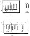
- Fig. 5 illustrates the layout geometry of an IDT using reflector gratings 52 to form a SPUDT 50.
- the dimension for each finger 12, space and reflector 52 is ⁇ /4 (see for example C. K. CAMPBELL, Surface Acoustic Wave Devices for Mobile and Wireless Communications, Boston, MA: Academic Press, 1998, Chapter 12).
- the substrate 14 has been omitted for clarity, but it is to be understood that IDT structures may be fabricated on a common substrate.
- the SPUDT 50 operates in a similar fashion to produce a SAW in response to a pulse at the pulse input/output terminal.
- Each set of fingers 12 produces a SAW that propagates in both directions perpendicular to the fingers.
- the reflector gratings 52 in SPUDT 50 reflect any SAWs impinging thereon and propagating in a direction from the right hand side to the left hand side of Fig. 5 in the opposite direction, from left to right.
- the spacing of reflector gratings 52 and fingers 12 prevents destructive interference between the reflected waves and waves produced by the fingers 12 which propagate in the desired direction.
- the SPUDT reflector gratings are placed judiciously with respect to adjacent IDTs. This placement selection is dependent on whether the reflection gratings are open or short circuited, as well as on the piezoelectric substrate type involved.
- the SPUDT 50 outputs a much higher power SAW propagating in the direction indicated by the arrow in Fig. 5.
- the "right to left" SAW produced by the leftmost set of fingers 12 in Fig. 5 is the only SAW component which does not contribute to the SAW output in the indicated direction.
- roughly half of the total signal power generated in the expander/compressor 22 propagates toward the TX IDT 24.
- the upper terminal in Fig. 5 may be either grounded, in single-ended designs, or connected as a pulse input/output terminal in differential designs.
- each of the three groups of fingers includes four fingers. Starting at the left hand side of the Figure, the first finger of each of the first two sets is attached to the top rail, but in the third set, the first finger is attached to the bottom rail. This indicates a 180° phase shift as what is derived from a + + - configuration.
- a SAW-based communication system 60 has a SPUDT-type expander 50a, a transmit (TX) IDT 56, a SPUDT-type compressor 50b and a receive (RX) IDT 64. These structures are in-line with each other as shown in Fig. 6. As discussed above in relation to Fig. 2, these structures may be placed on a suitable piezoelectric substrate using thin film lithographic procedures.
- a narrow pulse which represents digital data and can be generated by using simple digital circuitry or an existing data source is injected into the SPUDT 50a of Fig. 6 through pulse input and output terminal 54a to activate a piezoelectric effect that converts electrical to mechanical (acoustic wave) motion.
- the acoustic waves are coded depending on the geometry of the SPUDT 50a. These acoustic waves then propagate within the substrate to the TX IDT 56.
- the coded acoustic waves are then transformed to an electrical coded RF signal within the proximity of the TX IDT 56.
- the TX IDT 56 is attached to a suitable antenna 62 through the band pass filter 61, the coded RF signal can propagate throughout the air.
- Pulse output 54b is not read during signal transmission to prevent erroneous data detection.
- a coded electrical signal that enters the RX IDT 64 via antenna 62 and band pass filter 61 generates an acoustic wave that propagates towards the SPUDT-type compressor 50b.
- An autocorrelation function is passively performed in the SPUDT 50b and if the coded waveform from the RX IDT 64 matches with the code on the SPUDT 50b, a peak is generated at the pulse output terminal 54b.
- the reflection gratings in compressor 50b enhance conversion of the SAW from RX IDT 64 into electrical energy.
- the peak produced by the SPUDT-type compressor 50b can represent digital data.
- the presence of a peak within a bit period may be interpreted as a '1' data bit, whereas the absence of a peak would represent a '0' bit.
- the coding of the SPUDT-type expander 50a and compressor 50b and the associated autocorrelation function performed by the SPUDT as discussed above are determined by the finger geometry of the SPUDT.
- a preferred coding scheme is a Barker code. Barker codes are particularly useful for IDT coding, since they minimize the energy in side lobes associated with a compressed pulse generated by the autocorrelation function performed on a SAW input to an expander/compressor IDT.
- the SPUDTs 50a and 50b as shown in Fig. 6 are coded with a + + - Barker code.
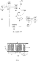
- Fig. 7 shows an example of the autocorrelation function relating to a 5 bit Barker code ( + + + - + ) performed by an expander/compressor SPUDT or IDT when a received signal is converted to a SAW by a receive IDT such as RX IDT 64.
- the autocorrelation function is mathematically equivalent to a series of shift and add operations as shown in Fig. 7 and generates the peak and associated side lobes shown at the bottom of Fig. 7 if the received signal was generated with an identically-coded SPUDT or IDT.
- the amplitude of the autocorrelation peak is proportional to the code length N, which is 5 in the example shown in Fig. 7, whereas the side lobes are amplitude 1.
- Fig. 8 shows a differential design of the system of Fig. 6.
- both the upper and lower sets of fingers in the TX IDT 56' and RX IDT 64' are connected to antenna 62' and band pass filter 61'.
- the filter 61' and antenna 62' must also be differential components.
- Expander SPUDT 50a' and compressor SPUDT 50b' may be single-ended, with terminals 55a' and 55b' grounded as shown in Fig. 6, or differential, wherein terminal 55a' is a pulse input terminal and terminal 55b' is a pulse output terminal.
- the differential system in Fig. 8 operates similarly to the system of Fig. 6, as will be apparent to those skilled in the art.
- a SPUDT over an IDT in a SAW-based communication system includes the direction of significantly more of the acoustic waves generated by an expander toward the transmit element, TX IDT 56 for example, as well as improved conversion of input SAW mechanical energy into electrical energy.
- the SPUDT design technique can effect a significant reduction in device insertion loss and thereby enhance signal-processing performance. This same principle may also be exploited on the transmit and receive sides of a communication system, as shown in Fig. 9.
- the transmit IDT and the receive IDT are SPUDT-type IDTs 72 and 74, which include reflection gratings.
- TX SPUDT 72 improves conversion of the SAW output by expander SPUDT 50a to an electrical signal.
- Fig. 10 shows a differential implementation of the SPUDT-type system of Fig. 9.
- the inventive arrangements disclosed above can reduce the cost, power consumption, size and complexity of virtually any short range communications system.
- This SAW based technology will allow communication devices to be placed in power sensitive applications such as a wireless earpiece to allow the user a longer "talk-time" over Bluetooth devices.
- SPUDT-type SAW-based communication systems may be incorporated into short range communication systems, including any situation for which Bluetooth was designed.
- FIG. 112 denotes an earpiece
- 114 is a mobile wireless communication device
- 116 is a holder or cradle for holding the device 114 and coupling device 114 to a personal computer (PC) 120.
- the earpiece 112, device 114 and cradle 116 incorporate a SAW communication device as disclosed above. This allows a user to communicate audibly between the wireless communication device 114, which may for example be carried on their belt or person, and the wireless earpiece 112 with a built-in microphone, as indicated at 118a in Fig. 11.
- This system could be then expanded to include communication between the earpiece 112 and the personal computer 120, as indicated by 118b, when a SAW system in cradle 116 is attached to the PC via a bus connection.
- This system may then be further expanded to include network communications designated 118c in Fig. 11 between the wireless device 114 on the belt or person with the PC 120 to incorporate connectivity via small pico-cell networks.
- a further extension of the communication systems according to the first and second embodiments could be a personal area network (PAN) based on SAW technology rather than the more excessive Bluetooth strategy.
- PAN personal area network
- the SPUDT design techniques discussed above are applied to passive SAW RF systems.
- SAW devices usually perform only as RF expanders.
- a passive system 130 comprises two IDTs 122 and 124.
- a pulse that has been sent out by a local requesting unit is received at the antenna 128 and excites IDT 122 to produce an acoustic wave.
- This wave then propagates to a SPUDT-type coded IDT 124 that has a suitable termination 126 connected across its terminals 132 and 134 to produce a reflection coefficient of magnitude 1.
- Termination 126 could be an open or short circuit termination, which will reexcite the coded SPUDT-type IDT 124 to produce a coded acoustic wave back to the IDT 122 that is connected to the antenna 128. The result is that an impulse sent out by a local requesting unit excites a coded SPUDT which then returns back to the requesting unit a coded RF waveform.
- autocorrelation of the coded waveform returned from the device 130 would preferably be performed by a DSP or other conventional signal processing circuitry, such that different codes can be used for different SPUDT-type IDTs such as IDT 124.
- a separate coded IDT must be provided in the requesting unit for each different code embodied in all devices 130 with which communication is desired. This would severely limit the number of devices 130 that could be deployed.
- the size of the complete SAW device 130 could be on the order of 3mm square. This would allow the device to be incorporated into labels such as shipping or address labels, equipment nameplates, adhesive stickers such as vehicle license plate stickers and other forms of identification tags.
- the code embodied in the SPUDT 124 could for example be a code that provides information about an item to which the device 130 is attached. Device 130 could therefore be implemented in an identification or location system for example.
- IDT 122 in Fig. 12 is a single-ended IDT, a differential design is also contemplated, as shown in Fig. 13.
- the IDT connected to the antenna 128 could also be a SPUDT-type IDT as in Figs. 14 and 15.
- FIG. 16 shows a system into which passive SAW RF devices according to the third embodiment of the invention could be implemented.
- a requesting unit 150 which may for example be a hand-held unit with a display or part of a larger interrogation and tracking system, sends an RF pulse 144 to a label, tag or the like generally indicated at 160.
- the tag 160 includes a SAW device 130, 130', 140 or 140' and may be attached to or placed on or inside an item.
- the coded return signal 146 generated by the SAW device in tag 160 is received at the requesting device and processed to determine tag information. The information thus determined may for example be displayed to a user or operator of the requesting device 150, forwarded from the requesting unit 150 to an information, tracking or billing system for further processing, or both.
Landscapes
- Physics & Mathematics (AREA)
- Acoustics & Sound (AREA)
- Engineering & Computer Science (AREA)
- Radar, Positioning & Navigation (AREA)
- Remote Sensing (AREA)
- Computer Networks & Wireless Communication (AREA)
- General Physics & Mathematics (AREA)
- Surface Acoustic Wave Elements And Circuit Networks Thereof (AREA)
Priority Applications (1)
| Application Number | Priority Date | Filing Date | Title |
|---|---|---|---|
| EP07124123A EP1901427B1 (de) | 2000-06-02 | 2001-05-31 | Drahtloses Kommunikationssystem unter Verwendung von einphasigen, unidirektionalen akustischen Oberflächenwellenwandlerverfahren |
Applications Claiming Priority (2)
| Application Number | Priority Date | Filing Date | Title |
|---|---|---|---|
| US20915300P | 2000-06-02 | 2000-06-02 | |
| US209153P | 2000-06-02 |
Related Child Applications (1)
| Application Number | Title | Priority Date | Filing Date |
|---|---|---|---|
| EP07124123A Division EP1901427B1 (de) | 2000-06-02 | 2001-05-31 | Drahtloses Kommunikationssystem unter Verwendung von einphasigen, unidirektionalen akustischen Oberflächenwellenwandlerverfahren |
Publications (3)
| Publication Number | Publication Date |
|---|---|
| EP1160974A2 true EP1160974A2 (de) | 2001-12-05 |
| EP1160974A3 EP1160974A3 (de) | 2002-02-20 |
| EP1160974B1 EP1160974B1 (de) | 2008-01-02 |
Family
ID=22777568
Family Applications (2)
| Application Number | Title | Priority Date | Filing Date |
|---|---|---|---|
| EP07124123A Expired - Lifetime EP1901427B1 (de) | 2000-06-02 | 2001-05-31 | Drahtloses Kommunikationssystem unter Verwendung von einphasigen, unidirektionalen akustischen Oberflächenwellenwandlerverfahren |
| EP01113310A Expired - Lifetime EP1160974B1 (de) | 2000-06-02 | 2001-05-31 | Drahtloses Übertragungssystem mit einphasigen unidirektionalen akustischen Oberflächenwellenwandlertechniken |
Family Applications Before (1)
| Application Number | Title | Priority Date | Filing Date |
|---|---|---|---|
| EP07124123A Expired - Lifetime EP1901427B1 (de) | 2000-06-02 | 2001-05-31 | Drahtloses Kommunikationssystem unter Verwendung von einphasigen, unidirektionalen akustischen Oberflächenwellenwandlerverfahren |
Country Status (5)
| Country | Link |
|---|---|
| US (1) | US6462698B2 (de) |
| EP (2) | EP1901427B1 (de) |
| AT (2) | ATE501550T1 (de) |
| CA (1) | CA2349128C (de) |
| DE (2) | DE60144203D1 (de) |
Cited By (1)
| Publication number | Priority date | Publication date | Assignee | Title |
|---|---|---|---|---|
| EP1552567A4 (de) * | 2002-10-18 | 2008-09-03 | Rf Saw Components Inc | Oberflächenwellenidentifikationsetikett mit einem für codediskrimination ausgelegten interdigitalwandler und verfahren zu seinem betrieb und seiner herstellung |
Families Citing this family (15)
| Publication number | Priority date | Publication date | Assignee | Title |
|---|---|---|---|---|
| US6489950B1 (en) | 1998-06-26 | 2002-12-03 | Research In Motion Limited | Hand-held electronic device with auxiliary input device |
| US6278442B1 (en) | 1998-06-26 | 2001-08-21 | Research In Motion Limited | Hand-held electronic device with a keyboard optimized for use with the thumbs |
| US7705828B2 (en) | 1998-06-26 | 2010-04-27 | Research In Motion Limited | Dual-mode mobile communication device |
| US6825794B2 (en) * | 2000-06-02 | 2004-11-30 | Research In Motion Limited | Wireless communication system using surface acoustic wave (SAW) second harmonic techniques |
| US6717983B1 (en) * | 2000-09-19 | 2004-04-06 | Kohji Toda | Ultrasonic coding modem for digital network communication |
| EP1684477B1 (de) | 2001-06-18 | 2008-12-03 | Research In Motion Limited | System und Verfahren zur Verwaltung von Nachrichtenanlagen |
| US20030016735A1 (en) * | 2001-07-23 | 2003-01-23 | Edmonson Peter J. | Communication system for two-way exchange of information |
| US7084768B2 (en) * | 2002-03-21 | 2006-08-01 | Rf Saw Components, Inc. | Anti-collision interrogation pulse focusing system for use with multiple surface acoustic wave identification tags and method of operation thereof |
| JP2004260793A (ja) * | 2003-02-04 | 2004-09-16 | Murata Mfg Co Ltd | 弾性表面波フィルタ |
| US6907787B2 (en) * | 2003-04-30 | 2005-06-21 | Honeywell International Inc. | Surface acoustic wave pressure sensor with microstructure sensing elements |
| US7158763B2 (en) * | 2003-05-02 | 2007-01-02 | P. J. Edmonson Ltd. | Multi-IDT SAW hybrid communication system |
| US7082835B2 (en) * | 2003-06-18 | 2006-08-01 | Honeywell International Inc. | Pressure sensor apparatus and method |
| EP1678823A2 (de) * | 2003-10-08 | 2006-07-12 | RF Saw Components, Incorporated | Unidirektionaler einphasen-oberflächenwellenwandler und verbesserte reflektoren |
| US9097789B2 (en) * | 2012-03-13 | 2015-08-04 | Duke Loi | Apparatus and method for electromagnetic wave structure modulation |
| KR102417610B1 (ko) | 2016-03-03 | 2022-07-07 | 삼성전자주식회사 | 근거리 초고주파 레이더를 이용한 코드 판독 방법 및 장치 |
Family Cites Families (17)
| Publication number | Priority date | Publication date | Assignee | Title |
|---|---|---|---|---|
| US4247903A (en) * | 1979-01-08 | 1981-01-27 | United Technologies Corporation | Monolithic isolated gate FET saw signal processor |
| US4746830A (en) | 1986-03-14 | 1988-05-24 | Holland William R | Electronic surveillance and identification |
| US4749964A (en) * | 1986-12-08 | 1988-06-07 | R. F. Monolithics, Inc. | Superregenerative detector having a saw device in the feedback circuit |
| JP3254779B2 (ja) | 1993-01-05 | 2002-02-12 | 株式会社村田製作所 | 多電極形弾性表面波装置 |
| JP3484237B2 (ja) * | 1994-09-28 | 2004-01-06 | 日本碍子株式会社 | 弾性表面波デバイス |
| US5835990A (en) | 1995-06-16 | 1998-11-10 | Northern Telecom Limited | Longitudinally coupled double mode surface wave resonators |
| US5831492A (en) * | 1995-09-15 | 1998-11-03 | Sawtek Inc. | Weighted tapered spudt saw device |
| JPH09261121A (ja) | 1996-03-22 | 1997-10-03 | Kazuo Tsubouchi | 符号分割多重通信装置 |
| EP0800270B1 (de) | 1996-04-02 | 2003-09-10 | Matsushita Electric Industrial Co., Ltd. | Akustischer Oberflächenwellenfilter |
| DE19638370C2 (de) | 1996-09-19 | 2001-06-13 | Epcos Ag | Oberflächenwellenfilter für unsymmetrische/symmetrische und symmetrische/symmetrische Betriebsweise |
| FR2762458B1 (fr) | 1997-04-18 | 1999-07-09 | Thomson Csf | Dispositif a ondes acoustiques de surface a couplage par proximite a entrees/sorties differentielles |
| US5896071A (en) * | 1997-05-15 | 1999-04-20 | Northern Telecom Limited | Surface wave device balun resonator filters |
| DE19724258C2 (de) | 1997-06-09 | 2002-10-10 | Epcos Ag | Dualmode-Oberflächenwellenfilter |
| DE19907640A1 (de) * | 1998-03-25 | 1999-10-07 | Dresden Ev Inst Festkoerper | Akustisches Oberflächenwellenbauelement |
| JP2000036722A (ja) * | 1998-05-11 | 2000-02-02 | Tdk Corp | 弾性表面波装置の設計方法および弾性表面波装置 |
| JP3291255B2 (ja) * | 1998-09-22 | 2002-06-10 | 日本碍子株式会社 | 弾性表面波デバイス |
| US6242844B1 (en) * | 1999-12-28 | 2001-06-05 | Cts Corporation | Wide-band single-phase unidirectional transducer |
-
2001
- 2001-05-24 US US09/864,507 patent/US6462698B2/en not_active Expired - Lifetime
- 2001-05-28 CA CA002349128A patent/CA2349128C/en not_active Expired - Fee Related
- 2001-05-31 DE DE60144203T patent/DE60144203D1/de not_active Expired - Lifetime
- 2001-05-31 DE DE60132131T patent/DE60132131T2/de not_active Expired - Lifetime
- 2001-05-31 AT AT07124123T patent/ATE501550T1/de not_active IP Right Cessation
- 2001-05-31 EP EP07124123A patent/EP1901427B1/de not_active Expired - Lifetime
- 2001-05-31 EP EP01113310A patent/EP1160974B1/de not_active Expired - Lifetime
- 2001-05-31 AT AT01113310T patent/ATE382985T1/de not_active IP Right Cessation
Cited By (2)
| Publication number | Priority date | Publication date | Assignee | Title |
|---|---|---|---|---|
| EP1552567A4 (de) * | 2002-10-18 | 2008-09-03 | Rf Saw Components Inc | Oberflächenwellenidentifikationsetikett mit einem für codediskrimination ausgelegten interdigitalwandler und verfahren zu seinem betrieb und seiner herstellung |
| JP2008236810A (ja) * | 2002-10-18 | 2008-10-02 | Rf Saw Inc | コード弁別用に適応させたインターデジタル・トランスデューサを有する表面弾性波識別タグおよびその動作方法および製造方法 |
Also Published As
| Publication number | Publication date |
|---|---|
| CA2349128C (en) | 2006-07-11 |
| ATE501550T1 (de) | 2011-03-15 |
| DE60144203D1 (de) | 2011-04-21 |
| DE60132131D1 (de) | 2008-02-14 |
| EP1901427B1 (de) | 2011-03-09 |
| DE60132131T2 (de) | 2008-12-11 |
| EP1160974A3 (de) | 2002-02-20 |
| CA2349128A1 (en) | 2001-12-02 |
| EP1901427A1 (de) | 2008-03-19 |
| US20010053179A1 (en) | 2001-12-20 |
| ATE382985T1 (de) | 2008-01-15 |
| US6462698B2 (en) | 2002-10-08 |
| EP1160974B1 (de) | 2008-01-02 |
Similar Documents
| Publication | Publication Date | Title |
|---|---|---|
| US8463185B2 (en) | Wireless communication system using surface acoustic wave (SAW) second harmonic techniques | |
| US6462698B2 (en) | Wireless communication system using surface acoustic wave (SAW) single-phase unidirectional transducer (SPUDT) techniques | |
| CN100418104C (zh) | 表面声波变换器装置以及具有该装置的识别系统 | |
| US6104260A (en) | Surface acoustic wave filter with first and second filter tracks and balanced or unbalanced terminals | |
| JPWO1996024198A1 (ja) | スペクトラム拡散通信装置及び通信システム | |
| US7158763B2 (en) | Multi-IDT SAW hybrid communication system | |
| US5905324A (en) | Surface acoustic wave device and communication device employing the surface acoustic wave device | |
| Seifert et al. | SAW-based radio sensor and communication techniques | |
| Ostermayer et al. | Multiple access to SAW sensors using matched filter properties | |
| Hickernell | Surface acoustic wave devices: a rewarding past, a significant present, and a promising future | |
| CN115688848B (en) | Surface acoustic wave label structure adopting one mask plate and coding identification method thereof | |
| JP2000295061A (ja) | Sawフィルタ | |
| Brocato | LDRD 26573 Ultra-Low Power Spread Spectrum Receiver, FY02 Final Report | |
| Seifert et al. | SAW signal processing: Extendable by Si-ASICs? | |
| JPH10257015A (ja) | スペクトラム拡散復調回路及びスペクトラム拡散通信装置 | |
| Weigel | 18. Wireless Communications and Sensing Based | |
| JPH11168351A (ja) | 表面弾性波素子及びスペクトラム拡散通信装置 | |
| JP2001217681A (ja) | 弾性表面波コンボルバ | |
| JP2006174255A (ja) | 弾性表面波装置、無線送信機および無線受信機 |
Legal Events
| Date | Code | Title | Description |
|---|---|---|---|
| PUAI | Public reference made under article 153(3) epc to a published international application that has entered the european phase |
Free format text: ORIGINAL CODE: 0009012 |
|
| 17P | Request for examination filed |
Effective date: 20010628 |
|
| AK | Designated contracting states |
Kind code of ref document: A2 Designated state(s): AT BE CH CY DE DK ES FI FR GB GR IE IT LI LU MC NL PT SE TR |
|
| AX | Request for extension of the european patent |
Free format text: AL;LT;LV;MK;RO;SI |
|
| PUAL | Search report despatched |
Free format text: ORIGINAL CODE: 0009013 |
|
| AK | Designated contracting states |
Kind code of ref document: A3 Designated state(s): AT BE CH CY DE DK ES FI FR GB GR IE IT LI LU MC NL PT SE TR |
|
| AX | Request for extension of the european patent |
Free format text: AL;LT;LV;MK;RO;SI |
|
| AKX | Designation fees paid |
Free format text: AT BE CH CY DE DK ES FI FR GB GR IE IT LI LU MC NL PT SE TR |
|
| GRAP | Despatch of communication of intention to grant a patent |
Free format text: ORIGINAL CODE: EPIDOSNIGR1 |
|
| GRAS | Grant fee paid |
Free format text: ORIGINAL CODE: EPIDOSNIGR3 |
|
| GRAA | (expected) grant |
Free format text: ORIGINAL CODE: 0009210 |
|
| AK | Designated contracting states |
Kind code of ref document: B1 Designated state(s): AT BE CH CY DE DK ES FI FR GB GR IE IT LI LU MC NL PT SE TR |
|
| REG | Reference to a national code |
Ref country code: GB Ref legal event code: FG4D |
|
| REG | Reference to a national code |
Ref country code: IE Ref legal event code: FG4D |
|
| REG | Reference to a national code |
Ref country code: CH Ref legal event code: EP |
|
| REF | Corresponds to: |
Ref document number: 60132131 Country of ref document: DE Date of ref document: 20080214 Kind code of ref document: P |
|
| PG25 | Lapsed in a contracting state [announced via postgrant information from national office to epo] |
Ref country code: NL Free format text: LAPSE BECAUSE OF FAILURE TO SUBMIT A TRANSLATION OF THE DESCRIPTION OR TO PAY THE FEE WITHIN THE PRESCRIBED TIME-LIMIT Effective date: 20080102 |
|
| NLV1 | Nl: lapsed or annulled due to failure to fulfill the requirements of art. 29p and 29m of the patents act | ||
| PG25 | Lapsed in a contracting state [announced via postgrant information from national office to epo] |
Ref country code: FI Free format text: LAPSE BECAUSE OF FAILURE TO SUBMIT A TRANSLATION OF THE DESCRIPTION OR TO PAY THE FEE WITHIN THE PRESCRIBED TIME-LIMIT Effective date: 20080102 Ref country code: ES Free format text: LAPSE BECAUSE OF FAILURE TO SUBMIT A TRANSLATION OF THE DESCRIPTION OR TO PAY THE FEE WITHIN THE PRESCRIBED TIME-LIMIT Effective date: 20080413 Ref country code: CH Free format text: LAPSE BECAUSE OF FAILURE TO SUBMIT A TRANSLATION OF THE DESCRIPTION OR TO PAY THE FEE WITHIN THE PRESCRIBED TIME-LIMIT Effective date: 20080102 Ref country code: LI Free format text: LAPSE BECAUSE OF FAILURE TO SUBMIT A TRANSLATION OF THE DESCRIPTION OR TO PAY THE FEE WITHIN THE PRESCRIBED TIME-LIMIT Effective date: 20080102 |
|
| REG | Reference to a national code |
Ref country code: CH Ref legal event code: PL |
|
| PG25 | Lapsed in a contracting state [announced via postgrant information from national office to epo] |
Ref country code: AT Free format text: LAPSE BECAUSE OF FAILURE TO SUBMIT A TRANSLATION OF THE DESCRIPTION OR TO PAY THE FEE WITHIN THE PRESCRIBED TIME-LIMIT Effective date: 20080102 |
|
| ET | Fr: translation filed | ||
| PG25 | Lapsed in a contracting state [announced via postgrant information from national office to epo] |
Ref country code: PT Free format text: LAPSE BECAUSE OF FAILURE TO SUBMIT A TRANSLATION OF THE DESCRIPTION OR TO PAY THE FEE WITHIN THE PRESCRIBED TIME-LIMIT Effective date: 20080602 Ref country code: BE Free format text: LAPSE BECAUSE OF FAILURE TO SUBMIT A TRANSLATION OF THE DESCRIPTION OR TO PAY THE FEE WITHIN THE PRESCRIBED TIME-LIMIT Effective date: 20080102 |
|
| PG25 | Lapsed in a contracting state [announced via postgrant information from national office to epo] |
Ref country code: SE Free format text: LAPSE BECAUSE OF FAILURE TO SUBMIT A TRANSLATION OF THE DESCRIPTION OR TO PAY THE FEE WITHIN THE PRESCRIBED TIME-LIMIT Effective date: 20080402 Ref country code: DK Free format text: LAPSE BECAUSE OF FAILURE TO SUBMIT A TRANSLATION OF THE DESCRIPTION OR TO PAY THE FEE WITHIN THE PRESCRIBED TIME-LIMIT Effective date: 20080102 |
|
| PLBE | No opposition filed within time limit |
Free format text: ORIGINAL CODE: 0009261 |
|
| STAA | Information on the status of an ep patent application or granted ep patent |
Free format text: STATUS: NO OPPOSITION FILED WITHIN TIME LIMIT |
|
| 26N | No opposition filed |
Effective date: 20081003 |
|
| PG25 | Lapsed in a contracting state [announced via postgrant information from national office to epo] |
Ref country code: MC Free format text: LAPSE BECAUSE OF NON-PAYMENT OF DUE FEES Effective date: 20080531 |
|
| PG25 | Lapsed in a contracting state [announced via postgrant information from national office to epo] |
Ref country code: IE Free format text: LAPSE BECAUSE OF NON-PAYMENT OF DUE FEES Effective date: 20080602 |
|
| PG25 | Lapsed in a contracting state [announced via postgrant information from national office to epo] |
Ref country code: CY Free format text: LAPSE BECAUSE OF FAILURE TO SUBMIT A TRANSLATION OF THE DESCRIPTION OR TO PAY THE FEE WITHIN THE PRESCRIBED TIME-LIMIT Effective date: 20080102 |
|
| PG25 | Lapsed in a contracting state [announced via postgrant information from national office to epo] |
Ref country code: IT Free format text: LAPSE BECAUSE OF FAILURE TO SUBMIT A TRANSLATION OF THE DESCRIPTION OR TO PAY THE FEE WITHIN THE PRESCRIBED TIME-LIMIT Effective date: 20080102 |
|
| PG25 | Lapsed in a contracting state [announced via postgrant information from national office to epo] |
Ref country code: LU Free format text: LAPSE BECAUSE OF NON-PAYMENT OF DUE FEES Effective date: 20080531 |
|
| PG25 | Lapsed in a contracting state [announced via postgrant information from national office to epo] |
Ref country code: TR Free format text: LAPSE BECAUSE OF FAILURE TO SUBMIT A TRANSLATION OF THE DESCRIPTION OR TO PAY THE FEE WITHIN THE PRESCRIBED TIME-LIMIT Effective date: 20080102 |
|
| PG25 | Lapsed in a contracting state [announced via postgrant information from national office to epo] |
Ref country code: GR Free format text: LAPSE BECAUSE OF FAILURE TO SUBMIT A TRANSLATION OF THE DESCRIPTION OR TO PAY THE FEE WITHIN THE PRESCRIBED TIME-LIMIT Effective date: 20080403 |
|
| REG | Reference to a national code |
Ref country code: DE Ref legal event code: R082 Ref document number: 60132131 Country of ref document: DE Representative=s name: MERH-IP MATIAS ERNY REICHL HOFFMANN, DE |
|
| REG | Reference to a national code |
Ref country code: DE Ref legal event code: R082 Ref document number: 60132131 Country of ref document: DE Representative=s name: MERH-IP MATIAS ERNY REICHL HOFFMANN, DE Effective date: 20140925 Ref country code: DE Ref legal event code: R081 Ref document number: 60132131 Country of ref document: DE Owner name: BLACKBERRY LIMITED, WATERLOO, CA Free format text: FORMER OWNER: RESEARCH IN MOTION LTD., WATERLOO, ONTARIO, CA Effective date: 20140925 Ref country code: DE Ref legal event code: R082 Ref document number: 60132131 Country of ref document: DE Representative=s name: MERH-IP MATIAS ERNY REICHL HOFFMANN PATENTANWA, DE Effective date: 20140925 |
|
| REG | Reference to a national code |
Ref country code: FR Ref legal event code: PLFP Year of fee payment: 16 |
|
| PGFP | Annual fee paid to national office [announced via postgrant information from national office to epo] |
Ref country code: DE Payment date: 20160527 Year of fee payment: 16 Ref country code: GB Payment date: 20160527 Year of fee payment: 16 |
|
| PGFP | Annual fee paid to national office [announced via postgrant information from national office to epo] |
Ref country code: FR Payment date: 20160530 Year of fee payment: 16 |
|
| REG | Reference to a national code |
Ref country code: DE Ref legal event code: R119 Ref document number: 60132131 Country of ref document: DE |
|
| GBPC | Gb: european patent ceased through non-payment of renewal fee |
Effective date: 20170531 |
|
| REG | Reference to a national code |
Ref country code: FR Ref legal event code: ST Effective date: 20180131 |
|
| PG25 | Lapsed in a contracting state [announced via postgrant information from national office to epo] |
Ref country code: GB Free format text: LAPSE BECAUSE OF NON-PAYMENT OF DUE FEES Effective date: 20170531 Ref country code: DE Free format text: LAPSE BECAUSE OF NON-PAYMENT OF DUE FEES Effective date: 20171201 |
|
| PG25 | Lapsed in a contracting state [announced via postgrant information from national office to epo] |
Ref country code: FR Free format text: LAPSE BECAUSE OF NON-PAYMENT OF DUE FEES Effective date: 20170531 |