EP1161028A2 - Procédé et dispositif de multidiffusion - Google Patents
Procédé et dispositif de multidiffusion Download PDFInfo
- Publication number
- EP1161028A2 EP1161028A2 EP01113029A EP01113029A EP1161028A2 EP 1161028 A2 EP1161028 A2 EP 1161028A2 EP 01113029 A EP01113029 A EP 01113029A EP 01113029 A EP01113029 A EP 01113029A EP 1161028 A2 EP1161028 A2 EP 1161028A2
- Authority
- EP
- European Patent Office
- Prior art keywords
- multicast
- ipv4
- address
- ipv6
- packet
- Prior art date
- Legal status (The legal status is an assumption and is not a legal conclusion. Google has not performed a legal analysis and makes no representation as to the accuracy of the status listed.)
- Granted
Links
Images





Classifications
-
- H—ELECTRICITY
- H04—ELECTRIC COMMUNICATION TECHNIQUE
- H04L—TRANSMISSION OF DIGITAL INFORMATION, e.g. TELEGRAPHIC COMMUNICATION
- H04L12/00—Data switching networks
- H04L12/02—Details
- H04L12/16—Arrangements for providing special services to substations
- H04L12/18—Arrangements for providing special services to substations for broadcast or conference, e.g. multicast
- H04L12/185—Arrangements for providing special services to substations for broadcast or conference, e.g. multicast with management of multicast group membership
-
- H—ELECTRICITY
- H04—ELECTRIC COMMUNICATION TECHNIQUE
- H04L—TRANSMISSION OF DIGITAL INFORMATION, e.g. TELEGRAPHIC COMMUNICATION
- H04L12/00—Data switching networks
- H04L12/02—Details
- H04L12/16—Arrangements for providing special services to substations
- H04L12/18—Arrangements for providing special services to substations for broadcast or conference, e.g. multicast
- H04L12/1836—Arrangements for providing special services to substations for broadcast or conference, e.g. multicast with heterogeneous network architecture
-
- H—ELECTRICITY
- H04—ELECTRIC COMMUNICATION TECHNIQUE
- H04L—TRANSMISSION OF DIGITAL INFORMATION, e.g. TELEGRAPHIC COMMUNICATION
- H04L69/00—Network arrangements, protocols or services independent of the application payload and not provided for in the other groups of this subclass
- H04L69/08—Protocols for interworking; Protocol conversion
-
- H—ELECTRICITY
- H04—ELECTRIC COMMUNICATION TECHNIQUE
- H04L—TRANSMISSION OF DIGITAL INFORMATION, e.g. TELEGRAPHIC COMMUNICATION
- H04L9/00—Cryptographic mechanisms or cryptographic arrangements for secret or secure communications; Network security protocols
- H04L9/40—Network security protocols
Definitions
- the present invention relates to an IPv4-IPv6 multicast communicating method and an IPv4-IPv6 multicast communicating apparatus in a communications network system. More particularly, it relates to a method and an apparatus for implementing the multicast communication between an IPv4 terminal using IPv4 (i.e., Internet Protocol Version 4) as the communications protocol and an IPv6 terminal using IPv6 (i.e., Internet Protocol Version 6) as the communications protocol.
- IPv4 i.e., Internet Protocol Version 4
- IPv6 i.e., Internet Protocol Version 6
- IPv4 terminal As one example of the methods for implementing the communication between the IPv4 terminal and the IPv6 terminal, there can be cited a technology disclosed in USP 6, 118, 784 (JP-A-11-55319).
- This technology allows the communication between the IPv4 terminal and the IPv6 terminal in the following way:
- An IP address conversion table for managing the correspondence between an IPv4 address and an IPv6 address is created using DNS (i.e., Domain Name System) protocol extending technology in an apparatus located halfway in the communications path. Then, based on the IP address conversion table, an IPv4 header-IPv6 header conversion is executed, thereby allowing the communication to be implemented.
- DNS Domain Name System
- FIG. 1 illustrates the configuration diagram of a converting apparatus la according to the 1st embodiment of the present invention.
- the converting apparatus la which is positioned between an IPv4 network 101 and an IPv6 network 102, executes the IP header conversion mutually between an IPv4 multicast packet and an IPv6 multicast packet. Based on this IP header conversion processing, the converting apparatus la implements the IP multicast communication between the IPv4 terminal and the IPv6 terminal.
- the converting apparatus la includes an IP transmitting/receiving unit 2, a for-conversion IP address holding unit 3, an IP address conversion information holding unit 4, an IP multicast membership group managing unit 5, and an IP header converting unit 6.
- the IP transmitting/receiving unit 2 performs the transmittance/reception of the IPv4 multicast packet with the IPv4 network 101, and the transmittance/reception of the IPv6 multicast packet with the IPv6 network 102.
- the for-conversion IP address holding unit 3 holds an IPv4 unicast address, an IPv4 multicast address, an IPv6 unicast address, and an IPv6 multicast address, all of which are used for the IP header conversion.
- An IPv4 unicast address table 31 holds the IPv4 unicast address used for the IP header conversion.
- the IP addresses to be held by the for-conversion IP address holding unit 3 have been registered in advance in accordance with the instruction from a manager of the converting apparatus la.
- the following method is also allowable: The converting apparatus performs the communication with a DHCP server so as to automatically acquire unused addresses, then holding the unused addresses into the for-conversion IP address holding unit 3.
- An IPv4 multicast address table 32 holds the IPv4 multicast address used for the IP header conversion.
- An IPv6 unicast address table 33 holds the IPv6 unicast address used for the IP header conversion.
- An IPv6 multicast address table 34 holds the IPv6 multicast address used for the IP header conversion.
- the for-conversion IP address holding unit 3 holds and manages all of the IPv4 unicast address table 31, the IPv4 multicast address table 32, the IPv6 unicast address table 33, and the IPv6 multicast address table 34.
- the IP address conversion information holding unit 4 holds the IPv4 unicast address and the IPv6 unicast address, and the IPv4 multicast address and the IPv6 multicast address in a state of being made to correspond to each other, respectively.
- the IP address conversion information holding unit 4 converts the IPv4 multicast address into the IPv6 multicast address held in correspondence with the IPv4 multicast address.
- the IPv4 multicast address is an IPv4 transmission destination address of the IPv4 multicast packet broadcast (transmitted) by the IPv4 terminal on the IPv4 network 101.
- the IP address conversion information holding unit 4 converts the IPv4 unicast address into the IPv6 unicast address held in correspondence with the IPv4 unicast address, the IPv4 unicast address being an IPv4 transmission source address of the above-described IPv4 multicast packet.
- the IP address conversion information holding unit 4 converts the IPv6 multicast address into the IPv4 multicast address held in correspondence with the IPv6 multicast address.
- the IPv6 multicast address is an IPv6 transmission destination address of the IPv6 multicast packet broadcast (transmitted) by the IPv6 terminal on the IPv6 network 102.
- the IP address conversion information holding unit 4 converts the IPv6 unicast address into the IPv4 unicast address held in correspondence with the IPv6 unicast address, the IPv6 unicast address being an IPv6 transmission source address of the above-described IPv6 multicast packet.
- An IP address conversion table 41 holds the following addresses, respectively: The IPv4 transmission destination address of the IPv4 multicast packet, which has been received by the converting apparatus la, and the IPv6 multicast address corresponding thereto, and the IPv4 transmission source address of the above-described IPv4 multicast packet and the IPv6 unicast address corresponding thereto. Also, the IP address conversion table 41 holds the following addresses, respectively: The IPv6 transmission destination address of the received IPv6 multicast packet and the IPv4 multicast address corresponding thereto, and the IPv6 transmission source address of the above-described IPv6 multicast packet and the IPv4 unicast address corresponding thereto.
- the IP address conversion information holding unit 4 holds and manages the above-described IP address conversion table 41.
- the IP multicast membership group managing unit 5 performs the membership state management of the converting apparatus la into an IPv4 multicast group and an IPv6 multicast group. Also, the IP multicast membership group managing unit 5 instructs the IP address conversion information holding unit 4 to register the IPv4 multicast address of the IPv4 multicast group of which the converting apparatus 1a is a member and the IPv6 multicast address corresponding thereto, or the IPv6 multicast address of the IPv6 multicast group of which the converting apparatus la is a member and the IPv4 multicast address corresponding thereto.
- An IPv4 multicast membership table 51 holds the IPv4 multicast address of the IPv4 multicast group of which the converting apparatus la is the member.
- an IPv6 multicast membership table 52 holds the IPv6 multicast address of the IPv6 multicast group of which the converting apparatus la is the member.
- the IP multicast membership group managing unit 5 holds and manages the IPv4 multicast membership table 51 and the IPv6 multicast membership table 52.
- the IP header converting unit 6 executes the IP header conversion toward the IPv4 multicast packet transferred from the IP transmitting/receiving unit 2, thereby creating the IPv6 multicast packet. Furthermore, the IP header converting unit 6 instructs the IP transmitting/receiving unit 2 to send out the created IPv6 multicast packet to the IPv6 network 102.
- FIG. 14(a) illustrates an IPv6 header format.
- the IPv6 header format includes the following fields: The version number of IPv6, i.e., "6", is stored into a "Version” field.
- the priority of a processing at the time when a router relays the packet on a network is stored into a "Priority” field.
- the identifier at the time of performing a priority control or the like is stored into a "Flow Label” field.
- the length of the data portion resulting from removing the IPv6 header portion from the packet is stored into a "Payload Length” field.
- the identifier as to the header of which higher-order layer's protocol will follow next to the IPv6 header or the like is stored into a "Next Header Identifier” field.
- the maximum transfer number of the packet is stored into a "Hop Limit” field.
- the transmission source IP address is stored into a "Transmission Source IP Address” field
- the transmission destination IP address is stored into a
- FIG. 14(b) illustrates an IPv4 header format.
- the IPv4 header format includes the following fields: The version number of IPv4, i.e., "4", is stored into a "Version” field. The length of the IPv4 header itself is stored into a "Header Length” field. The information indicating the service quality of a communications processing is stored into a "Service Type” field. The size of the entire packet resulting from adding the IPv4 header to the data block dealt with in the IP is stored into a "Packet Length” field. The identifier that is used as the reference information when transferring the data to the higher-order layer is stored into an "Identifier" field.
- the control information on the division of the packet is stored into a "Fragment Offset” field.
- the information indicating where the divided data (i.e., the fragments) have been positioned within the original data is stored into a "Flag” field.
- the time during which the packet may exist on the network is stored into a "Time To Live” field.
- the information indicating what the higher-order layer's protocol is is stored into a "Protocol” field.
- the checksum of the IP header is stored into a "Header Checksum” field.
- the transmission source IP address is stored into a "Transmission Source IP Address” field
- the transmission destination IP address is stored into a "Transmission Destination IP Address” field.
- the IP header converting unit 6 executes the processing of converting the IPv4 header to the IPv6 header, both of which are illustrated in FIG. 14, or the processing of converting the IPv6 header to the IPv4 header. Then, the converting unit 6 sets the values in the respective fields within the IPv4 or the IPv6 header format after having been converted.
- an attention will be focused on, in particular, the address conversion of the transmission source IP address and the transmission destination IP address out of the IP header conversion processing. Accordingly, the description will be given mainly regarding the conversion processing of the "Transmission Source IP Address" field and the "Transmission Destination IP Address" field.
- the IP header converting unit 6 makes an inquiry of the IP address conversion information holding unit 4, thereby acquiring the IPv6 multicast address corresponding to the IPv4 transmission destination address of the IPv4 multicast packet. Then, using the IPv6 multicast address acquired from the IP address conversion information holding unit 4, the IP header converting unit 6 converts the IPv4 transmission destination address into the IPv6 transmission destination address. Similarly, the IP header converting unit 6 makes an inquiry of the IP address conversion information holding unit 4, thereby acquiring the IPv6 unicast address corresponding to the IPv4 transmission source address of the IPv4 multicast packet. Then, using the IPv6 unicast address acquired from the IP address conversion information holding unit 4, the IP header converting unit 6 converts the IPv4 transmission source address into the IPv6 transmission source address.
- the IP header converting unit 6 creates the IPv4 multicast packet from the IPv6 multicast packet transferred from the IP transmitting/ receiving unit 2, then instructing the IP transmitting/ receiving unit 2 to send out the IPv4 multicast packet to the IPv4 network 101.
- the IP header converting unit 6 makes an inquiry of the IP address conversion information holding unit 4, thereby acquiring the IPv4 multicast address corresponding to the IPv6 transmission destination address of the IPv6 multicast packet. Then, using the acquired IPv4 multicast address, the IP header converting unit 6 converts the IPv6 transmission destination address of the above-described IPv6 multicast packet into the IPv4 transmission destination address.
- the IP header converting unit 6 makes an inquiry of the IP address conversion information holding unit 4, thereby acquiring the IPv4 unicast address corresponding to the IPv6 transmission source address of the IPv6 multicast packet. Then, using the acquired IPv4 unicast address, the IP header converting unit 6 converts the IPv6 transmission source address of the above-described IPv6 multicast packet into the IPv4 transmission source address.
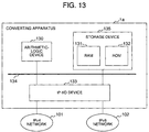
- FIG. 13 illustrates an example of the hardware configuration of the converting apparatus illustrated in FIG. 1.
- the converting apparatus la includes the following devices: An IP-I/O device 133 for establishing the connection with the IPv4 network 101 and the IPv6 network 102, a storage device 135 including, for example, a RAM 131, a ROM 132, and so on, and an arithmetic-logic device 130 for executing programs stored in the storage device 135 and performing the processing of various types of data stored in the storage device 135.
- the IP-I/O device 133, the storage device 135, and the arithmetic-logic device 130 are connected to each other through a bus 134 or the like.
- the converting apparatus 1a may have the other storage device such as a hard disk. In this case, the other storage device such as the hard disk is not necessarily connected directly to the bus 134.
- the IP transmitting/receiving unit 2 illustrated in FIG. 1 includes the IP-I/O device 133, i.e., a network interface for performing the transmittance/reception of the IP (i.e., Internet Protocol) packets in FIG. 13, a program that is held in the storage device 135 and is needed for the operation of the IP transmitting/receiving unit 2, and the arithmetic-logic device 130 for executing the program.
- IP i.e., Internet Protocol
- the IP-I/O device 133 may perform the transmittance/reception processing of the packets for the IPv4 network 101 and the IPv6 network 102 in the following configuration:
- the IP-I/O device 133 is not controlled by the arithmetic-logic device 130 positioned in the different place, but the IP-I/O device 133 itself has the arithmetic-logic device 130 and the storage device 135 inside.
- Each of the for-conversion IP address holding unit 3, the IP address conversion information holding unit 4, the IP multicast membership group managing unit 5, and the IP header converting unit 6 illustrated in FIG. 1 includes a program that is held in the storage device 135 and is needed for the operation of each unit, and the arithmetic-logic device 130 for executing the program.
- FIG. 2 illustrates the configuration diagram of the IPv4 unicast address table 31.
- the IPv4 unicast addresses used for the IP header conversion are registered in advance into the IPv4 unicast address table 31 in accordance with the instruction from the manager of the converting apparatus la. It is assumed that, in FIG. 2, the IPv4 unicast addresses of 133. 144. 93. 100 - 133. 144. 93. 200 have been registered into the IPv4 unicast address table 31 in accordance with the instruction from the manager.
- FIG. 3 illustrates the configuration diagram of the IPv4 multicast address table 32.
- the IPv4 multicast addresses used for the IP header conversion are registered in advance into the IPv4 multicast address table 32 in accordance with the instruction from the manager of the converting apparatus la. It is assumed that, in FIG. 3, the IPv4 multicast addresses of 238. 0. 0. 100 - 238. 0. 0. 200 have been registered into the IPv4 multicast address table 32 in accordance with the instruction from the manager.
- FIG. 4 illustrates the configuration diagram of the IPv6 unicast address table 33.
- the IPv6 unicast addresses used for the IP header conversion are registered in advance into the IPv6 unicast address table 33 in accordance with the instruction from the manager of the converting apparatus la. It is assumed that, in FIG. 4, the IPv6 unicast addresses of 1 : : 100 ⁇ 1 : : 200 have been registered into the IPv6 unicast address table 33 in accordance with the instruction from the manager.
- FIG. 5 illustrates the configuration diagram of the IPv6 multicast address table 34.
- the IPv6 multicast addresses used for the IP header conversion are registered in advance into the IPv6 multicast address table 34 in accordance with the instruction from the manager of the converting apparatus 1a. It is assumed that, in FIG. 5, the IPv6 multicast addresses of ffle : : 100 - ffle : : 200 have been registered into the IPv6 multicast address table 34 in accordance with the instruction from the manager.
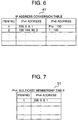
- FIG. 6 illustrates the configuration diagram of the IP address conversion table 41.
- the IP address conversion table 41 holds the IPv4 multicast addresses and the IPv6 multicast addresses in correspondence with each other, the IPv4 multicast addresses being the IPv4 transmission destination addresses of the IPv4 multicast packets received by the converting apparatus la, the IPv6 multicast addresses having been acquired from the for-conversion IP address holding unit 3 by the instruction from the IP multicast membership group managing unit 5.
- the IP address conversion table 41 holds the IPv4 unicast addresses and the IPv6 unicast addresses in correspondence with each other, the IPv4 unicast addresses being the IPv4 transmission source addresses of the IPv4 multicast packets received by the converting apparatus la, the IPv6 unicast addresses having been acquired from the for-conversion IP address holding unit 3 by the instruction from the IP address conversion information holding unit 4.
- the IP address conversion table 41 holds the IPv6 multicast addresses and the IPv4 multicast addresses in correspondence with each other, the IPv6 multicast addresses being the IPv6 transmission destination addresses of the IPv6 multicast packets received by the converting apparatus 1a, the IPv4 multicast addresses having been acquired from the for-conversion IP address holding unit 3 by the instruction from the IP multicast membership group managing unit 5.
- the IP address conversion table 41 holds the IPv6 unicast addresses and the IPv4 unicast addresses in correspondence with each other, the IPv6 unicast addresses being the IPv6 transmission source addresses of the above-described IPv6 multicast packets, the IPv4 unicast addresses having been acquired from the for-conversion IP address holding unit 3 by the instruction from the IP address conversion information holding unit 4.
- FIG. 7 illustrates the configuration diagram of the IPv4 multicast membership table 51.
- the IPv4 multicast addresses of the IPv4 multicast group, of which the converting apparatus la has become a member in accordance with the instruction from the manager of the converting apparatus la, are registered into the IPv4 multicast membership table 51.
- FIG. 8 illustrates the configuration diagram of the IPv6 multicast membership table 52.
- the IPv6 multicast addresses of the IPv6 multicast group, of which the converting apparatus la has become a member in accordance with the instruction from the manager of the converting apparatus la, are registered into the IPv6 multicast membership table 52.
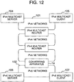
- FIG. 9 illustrates the schematic diagram of a communications network system where the IPv4 network 101 and the IPv6 network 102 are connected to each other through the converting apparatus la.
- An IPv4 multicast server 104 and an IPv4 multicast client 105 are connected to the IPv4 network 101.
- the IPv4 multicast server 104 broadcasts (transmits) a multicast packet in compliance with IPv4, and the IPv4 multicast client 105 receives the multicast packet in compliance with IPv4.
- an IPv6 multicast server 106 and an IPv6 multicast client 107 are connected to the IPv6 network 102.
- the IPv6 multicast server 106 broadcasts (transmits) a multicast packet in compliance with IPv6, and the IPv6 multicast client 107 receives the multicast packet in compliance with IPv6.
- IPv4 address 133. 144. 93. 1 and an IPv6 address 1 : : 1 have been assigned to the converting apparatus 1a.
- IPv4 address 133. 144. 93. 2 has been assigned to the IPv4 multicast server 104.
- IPv4 address 133. 144. 93. 3 has been assigned to the IPv4 multicast client 105.
- IPv6 address 1 : : 2 has been assigned to the IPv6 multicast server 106.
- IPv6 address 1 : : 3 has been assigned to the IPv6 multicast client 107.
- the IPv4 multicast server 104 broadcasts (transmits), to the IPv4 network 101, an IPv4 multicast packet the destination address of which is an IPv4 multicast address (238. 0. 0. 1).
- the IPv6 multicast server 106 broadcasts (transmits), to the IPv6 network 102, an IPv6 multicast packet the destination address of which is an IPv6 multicast address (ffle : : 1).
- the IPv4 network 101 and the IPv6 network 102 are physically isolated completely. However, even in the case where the IPv4 network 101 and the IPv6 network 102 exist in a mixed manner within the physically same network, the explanation given below concerning the embodiment guarantees that the converting apparatus la will function in much the same way.
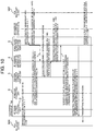
- FIGS. 10 and 11 illustrate a flowchart in the following case: Using the IPv4 multicast address of 238. 0. 0. 1 as the destination address, the IPv4 multicast server 104 broadcasts (transmits) the IPv4 multicast packet to the IPv4 network 101. Next, the converting apparatus la receives the IPv4 multicast packet so as to subject the packet to the IP header conversion processing, then sending out the converted packet to the IPv6 network 102.
- the IPv4 multicast server 104 broadcasts (transmits), to the IPv4 network 101, the IPv4 multicast packet the destination address of which is the IPv4 multicast address of 238. 0. 0. 1 (FIG. 10).
- the manager of the converting apparatus 1a instructs the IP multicast membership group managing unit 5 to make the converting apparatus la become a member of the multicast group of the IPv4 multicast address (238. 0. 0. 1).
- the IP multicast membership group managing unit 5 Having received the instruction from the manager, the IP multicast membership group managing unit 5, at first, registers the IPv4 multicast address (238. 0. 0. 1) into the IPv4 multicast membership table 51. Next, the IP multicast membership group managing unit 5 instructs the IP address conversion information holding unit 4 to register the IPv4 multicast address (238. 0. 0. 1) and the IPv6 multicast address corresponding thereto into the IP address conversion table 41.
- the IP address conversion information holding unit 4 searches the IP address conversion table 41 with the IPv4 multicast address (238. 0. 0. 1). If the applicable entry has been found out, the IP address conversion information holding unit 4 makes a report to the effect toward the IP multicast membership group managing unit 5. If no applicable entry has been found out, the IP address conversion information holding unit 4 acquires the IPv6 multicast address from the for-conversion IP address holding unit 3, then registering, into the IP address conversion table 41, the IPv6 multicast address in a state of being made to correspond to the IPv4 multicast address (238. 0. 0. 1). Moreover, toward the IP multicast membership group managing unit 5, the IP address conversion information holding unit 4 makes a report to the effect that the IPv4 multicast address (238. 0. 0.
- IP address conversion information holding unit 4 acquires the IPv6 multicast address (ffle : : 100) from the for-conversion IP address holding unit 3 so as to register the IPv6 multicast address into the IP address conversion table 41 in correspondence with the IPv4 multicast address (238. 0. 0. 1), then making the report to the effect toward the IP multicast membership group managing unit 5.
- the IP multicast membership group managing unit 5 instructs the IP transmitting/receiving unit 2 to transmit, to the IPv4 network 101, an "IGMP (i.e., Internet Group Management Protocol) Membership Report" message for indicating the membership into the IP multicast group of the IPv4 address (238. 0. 0. 1).
- IGMP Internet Group Management Protocol
- the IP transmitting/receiving unit 2 transmits the "IGMP Membership Report" message to the IPv4 network 101.
- the converting apparatus la executes the following processing, which is illustrated in FIG. 11.
- the converting apparatus la receives the IPv4 multicast packet from the IPv4 network 101 through the IP transmitting/receiving unit 2.
- the IP transmitting/receiving unit makes an inquiry of the IP multicast membership group managing unit 5 about whether or not the converting apparatus 1a has become a member of the multicast group of the IPv4 destination address of the IPv4 multicast packet that the converting apparatus la has received.
- the IP multicast membership group managing unit 5 checks whether or not the IPv4 destination address of the received IPv4 multicast packet has been registered in the IPv4 multicast membership table 51, then making a report on the result (i.e., membership-completed/membership-uncompleted) toward the IP transmitting/receiving unit 2.
- the IP multicast membership group managing unit 5 makes, toward the IP transmitting/receiving unit 2, the report to the effect of having been membership-completed.
- the IP transmitting/receiving unit 2 When receiving from the IP multicast membership group managing unit 5 the report of having been membership-uncompleted, the IP transmitting/receiving unit 2 disposes the IPv4 multicast packet. When receiving from the IP multicast membership group managing unit 5 the report of having been membership-completed, the IP transmitting/receiving unit 2 transfers the IPv4 multicast packet to the IP header converting unit 6. At this step in FIG. 11, since the IP transmitting/receiving unit 2 has received the report of having been membership-completed, the IP transmitting/receiving unit 2 transfers the IPv4 multicast packet to the IP header converting unit 6.
- the IP header converting unit 6 makes an inquiry of the IP address conversion information holding unit 4 about the IPv6 address corresponding to the IPv4 destination address and the IPv6 address corresponding to the IPv4 source address.
- the IP address conversion information holding unit 4 checks whether or not the IPv4 destination address has been registered in the IP address conversion table 41. If the IPv4 destination address has been registered therein, the IP address conversion information holding unit 4 makes, toward the IP header converting unit 6, a report on the IPv6 multicast address corresponding to the IPv4 destination address. If the IPv4 destination address has not been registered in the IP address conversion table 41, the IP address conversion information holding unit 4 makes, toward the IP header converting unit 6, a report to the effect of having not been registered. Here, since the IPv4 destination address (238. 0. 0. 1) has been registered in the IP address conversion table 41, the IP address conversion information holding unit 4 makes, toward the IP header converting unit 6, the report on the IPv6 multicast address corresponding thereto (ffle : : 100).
- the IP address conversion information holding unit 4 checks whether or not the IPv4 source address has been registered in the IP address conversion table 41. If the IPv4 source address has been registered therein, the IP address conversion information holding unit 4 makes, toward the IP header converting unit 6, a report on the IPv6 unicast address corresponding to the IPv4 source address. If the IPv4 source address has not been registered in the IP address conversion table 41, the IP address conversion information holding unit 4 acquires the IPv6 unicast address from the for-conversion IP address holding unit 3.
- the IP address conversion information holding unit 4 makes a report on the registered IPv6 unicast address toward the IP header converting unit 6.
- the IP address conversion information holding unit 4 acquires the IPv6 unicast address (1 : : 100) from the for-conversion IP address holding unit 3 so as to register the IPv6 unicast address into the IP address conversion table 41.
- the IP address conversion information holding unit 4 makes the report on the IPv6 unicast address (1 : : 100) toward the IP header converting unit 6.
- the IP header converting unit 6 receives, from the IP address conversion information holding unit 4, the reports on the IPv6 multicast address and the IPv6 unicast address that correspond to the IPv4 destination address of the received IPv4 multicast packet and the IPv4 source address thereof, respectively. Moreover, the IP header converting unit 6 creates the IPv6 multicast packet from the received IPv4 multicast packet by the IP header conversion, then instructing the IP transmitting/receiving unit 2 to send out the created IPv6 multicast packet to the IPv6 network 102. In the IP header conversion, the IP header converting unit 6 converts the IPv4 destination address into the IPv6 multicast address corresponding thereto, and converts the IPv4 source address into the IPv6 unicast address corresponding thereto.
- the IP header converting unit 6 When the IP header converting unit 6 has received, from the IP address conversion information holding unit 4, the report to the effect that the IPv4 destination address of the received IPv4 multicast packet has not been registered in the IP address conversion table 41, the IP header converting unit 6 disposes the received IPv4 multicast packet.
- the IP header converting unit 6 has received, from the IP address conversion information holding unit 4, the reports on the IPv6 multicast address (ffle : : 100) corresponding to the IPv4 destination address (238. 0. 0. 1) and the IPv6 unicast address (1 : : 100) corresponding to the IPv4 source address (133. 144. 93. 2). Furthermore, the IP header converting unit 6 converts the IPv4 destination address (238. 0. 0.
- the converting apparatus la creates the IPv6 multicast packet from the IPv4 multicast packet. In addition, the converting apparatus la sends out the created IPv6 multicast packet to the IPv6 network 102 through the IP transmitting/receiving unit 2.
- the IPv6 multicast client 107 becomes a member of the IPv6 multicast group of the IPv6 destination address (ffle : : 100) of the IPv6 multicast packet created by the converting apparatus la. This membership makes it possible for the IPv6 multicast client 107 to receive this IPv6 multicast packet.
- the above-described processing permits the IPv6 multicast client 107 to receive the IP multicast packet that the IPv4 multicast server 104 broadcasts (transmits) to the IPv4 network 101 with the IPv4 address of 238. 0. 0. 1.
- the converting apparatus 1a becomes a member of the group of the IPv6 multicast packet that the IPv6 multicast server 106 broadcasts (transmits) to the IPv6 network 102.
- the IP multicast membership group managing unit 5 instructs the IP transmitting/receiving unit 2 to transmit, to the IPv6 network 102, a "Multicast Listener Report" message described in, for example, RFC (i.e., Request For comments) 2710.
- RFC i.e., Request For comments
- the IP header converting unit 6 converts the IPv6 destination address (ffle : : 100) of the IPv6 multicast packet into the IPv4 multicast address held in the IP address conversion table 41 in correspondence with the IPv6 multicast address, and converts the IPv6 source address into the IPv4 unicast address held in the IP address conversion table 41 in correspondence with the IPv6 unicast address. Moreover, the converting apparatus la causes the IP header converting unit 6 to subject the IPv6 multicast packet received from the IPv6 network 102 to the IP header conversion processing by the IP header converting unit 6.
- the converting apparatus la sends out the created IPv4 multicast packet to the IPv4 network 101 through the IP transmitting/receiving unit 2.
- the above-described processing permits the IPv4 multicast client 105 to receive the IPv4 multicast packet created and sent out to the IPv4 network 101 by the converting apparatus 1a.
- the converting apparatus 1a has executed the IP header conversion toward the IPv4 multicast packet indicated by the manager. Other than this, it is also allowable to employ the configuration where the converting apparatus la executes the IP header conversion toward the IPv4 multicast packet that the converting apparatus la has automatically detected by monitoring the IPv4 network 101. Similarly, it is also allowable to employ the configuration where the converting apparatus 1a executes the IP header conversion toward the IPv6 multicast packet that the converting apparatus la has automatically detected by monitoring the IPv6 network 102.
- the IPv4 destination address (238. 0. 0. 1) of the IPv4 multicast packet that the IPv4 multicast server 104 broadcasts (transmits) to the IPv4 network 101 is converted into the IPv6 multicast address (ffle : : 100) acquired from the for-conversion IP address holding unit 3.
- the IPv4 destination address (238. 0. 0. 1) of the IPv4 multicast packet that the converting apparatus la has received is also allowed to be converted into a 128-bit IPv6 address resulting from adding a fixed pattern to the higher-order bits of the IPv4 destination address (e.g., ffle : : ffff : 238. 0. 0. 1).
- the case is also allowable where the converting apparatus la and the IPv4 multicast server 104 are connected to different IPv4 networks.
- the IGMP message that the converting apparatus la transmits in order to become the member of the IPv4 address of 238. 0. 0. 1 is received by an IPv4 multicast router 121.
- a multicast routing protocol operates between the IPv4 multicast router 121 and an IPv4 multicast router 122, thereby causing the IPv4 multicast packet to be transferred from the IPv4 multicast server 104 up to the converting apparatus la.
- the case is also allowable where the converting apparatus la and the IPv6 multicast server 104 are connected to different IPv6 networks.
- the present embodiments allow the IP multicast communication to be executed between the IPv4 terminal and the IPv6 terminal. As a result, it becomes possible for the IPv6 terminal to receive the IP multicast packet that is broadcast (transmitted) from the IPv4 terminal. Also, it becomes possible for the IPv4 terminal to receive the IP multicast packet that is broadcast (transmitted) from the IPv6 terminal.
Landscapes
- Engineering & Computer Science (AREA)
- Computer Networks & Wireless Communication (AREA)
- Signal Processing (AREA)
- Computer Security & Cryptography (AREA)
- Data Exchanges In Wide-Area Networks (AREA)
Applications Claiming Priority (2)
| Application Number | Priority Date | Filing Date | Title |
|---|---|---|---|
| JP2000164720 | 2000-05-30 | ||
| JP2000164720A JP4501230B2 (ja) | 2000-05-30 | 2000-05-30 | IPv4−IPv6マルチキャスト通信方法および装置 |
Publications (3)
| Publication Number | Publication Date |
|---|---|
| EP1161028A2 true EP1161028A2 (fr) | 2001-12-05 |
| EP1161028A3 EP1161028A3 (fr) | 2003-05-02 |
| EP1161028B1 EP1161028B1 (fr) | 2005-04-27 |
Family
ID=18668302
Family Applications (1)
| Application Number | Title | Priority Date | Filing Date |
|---|---|---|---|
| EP01113029A Expired - Lifetime EP1161028B1 (fr) | 2000-05-30 | 2001-05-28 | Procédé et dispositif de multidiffusion |
Country Status (5)
| Country | Link |
|---|---|
| US (3) | US6907037B2 (fr) |
| EP (1) | EP1161028B1 (fr) |
| JP (1) | JP4501230B2 (fr) |
| CN (4) | CN1291574C (fr) |
| DE (1) | DE60110311T2 (fr) |
Cited By (3)
| Publication number | Priority date | Publication date | Assignee | Title |
|---|---|---|---|---|
| EP1143680A3 (fr) * | 2000-04-03 | 2003-04-16 | Hitachi, Ltd. | Méthode pour la transmission de paquets de données vers multiples destinataires |
| WO2004028099A1 (fr) * | 2002-09-18 | 2004-04-01 | Fujitsu Limited | Appareil de connexion de groupes de multidiffusion |
| EP3133770A4 (fr) * | 2014-06-16 | 2017-09-20 | ZTE Corporation | Procédé et dispositif de multidiffusion ds-lite de passerelle locale |
Families Citing this family (83)
| Publication number | Priority date | Publication date | Assignee | Title |
|---|---|---|---|---|
| JP4365998B2 (ja) * | 2000-07-21 | 2009-11-18 | 株式会社日立製作所 | マルチキャスト通信方法および通信装置 |
| US8046452B2 (en) * | 2001-03-08 | 2011-10-25 | British Telecommunications Public Limited Company | Inter-network address translator that is separately addressable from address alias assignment process |
| EP1246425A1 (fr) * | 2001-03-30 | 2002-10-02 | BRITISH TELECOMMUNICATIONS public limited company | Réseaux à commutation de paquets |
| KR20030050506A (ko) * | 2001-12-18 | 2003-06-25 | 이경근 | 인터넷 프로토콜 버전6 멀티캐스트를 이용한 가상 학술회의 시스템 |
| JP3998983B2 (ja) * | 2002-01-17 | 2007-10-31 | 松下電器産業株式会社 | ユニキャスト−マルチキャスト変換装置および映像監視システム |
| US7440471B1 (en) * | 2002-04-17 | 2008-10-21 | Mcafee, Inc. | System and method for facilitating IPv6 protocol usage by an application program |
| US20030227916A1 (en) * | 2002-06-06 | 2003-12-11 | Toni Paila | System and method for the multicast distribution of multimedia messaging service messages |
| JP3688664B2 (ja) * | 2002-07-29 | 2005-08-31 | 株式会社東芝 | 中継装置及びネットワーク中継方法 |
| EP1414213B1 (fr) * | 2002-10-24 | 2011-11-30 | Alcatel Lucent | Classificateur de paquets et processor pour routeur de télécommunication |
| JP4073754B2 (ja) * | 2002-10-29 | 2008-04-09 | 富士通株式会社 | フレーム転送装置 |
| US20050111474A1 (en) * | 2002-10-31 | 2005-05-26 | Fujitsu Limited | IP multicast communication system |
| EP1420559A1 (fr) * | 2002-11-13 | 2004-05-19 | Thomson Licensing S.A. | Procédé et dispositif supportant un protocol tunnel 6to4 à l'aide d'un mécanisme de conversion des adresses de réseau |
| JP2004207840A (ja) * | 2002-12-24 | 2004-07-22 | Nec Corp | 無線リソース管理方法及びそれに用いる管理装置、基地局及び端末 |
| JP4077330B2 (ja) * | 2003-02-06 | 2008-04-16 | 富士通株式会社 | データ生成装置 |
| KR20040082655A (ko) * | 2003-03-19 | 2004-09-30 | 삼성전자주식회사 | 이중 스택 변환 메커니즘을 이용한 모바일 아이피 통신시스템 및 방법 |
| GB2405052A (en) * | 2003-08-12 | 2005-02-16 | Orange Personal Comm Serv Ltd | Packet data communications |
| JP4382528B2 (ja) | 2004-02-27 | 2009-12-16 | 富士通株式会社 | マルチキャストネットワーク装置,マルチキャストネットワークシステムおよびマルチキャスト方法 |
| WO2006015513A1 (fr) * | 2004-08-12 | 2006-02-16 | Intel Corporation | Procede et systeme de traitement de paquets a diffusion selective |
| US7362280B2 (en) * | 2004-08-18 | 2008-04-22 | Ruckus Wireless, Inc. | System and method for a minimized antenna apparatus with selectable elements |
| US7696946B2 (en) | 2004-08-18 | 2010-04-13 | Ruckus Wireless, Inc. | Reducing stray capacitance in antenna element switching |
| US7498996B2 (en) * | 2004-08-18 | 2009-03-03 | Ruckus Wireless, Inc. | Antennas with polarization diversity |
| US7965252B2 (en) * | 2004-08-18 | 2011-06-21 | Ruckus Wireless, Inc. | Dual polarization antenna array with increased wireless coverage |
| US7899497B2 (en) * | 2004-08-18 | 2011-03-01 | Ruckus Wireless, Inc. | System and method for transmission parameter control for an antenna apparatus with selectable elements |
| US7933628B2 (en) | 2004-08-18 | 2011-04-26 | Ruckus Wireless, Inc. | Transmission and reception parameter control |
| US7652632B2 (en) * | 2004-08-18 | 2010-01-26 | Ruckus Wireless, Inc. | Multiband omnidirectional planar antenna apparatus with selectable elements |
| US8031129B2 (en) | 2004-08-18 | 2011-10-04 | Ruckus Wireless, Inc. | Dual band dual polarization antenna array |
| US7880683B2 (en) | 2004-08-18 | 2011-02-01 | Ruckus Wireless, Inc. | Antennas with polarization diversity |
| US7193562B2 (en) | 2004-11-22 | 2007-03-20 | Ruckus Wireless, Inc. | Circuit board having a peripheral antenna apparatus with selectable antenna elements |
| US7292198B2 (en) * | 2004-08-18 | 2007-11-06 | Ruckus Wireless, Inc. | System and method for an omnidirectional planar antenna apparatus with selectable elements |
| KR100679014B1 (ko) | 2004-08-28 | 2007-02-06 | 삼성전자주식회사 | 이동 애드혹 네트워크에서의 노드간 통신 방법 |
| CN1758649B (zh) * | 2004-10-05 | 2010-04-28 | 华为技术有限公司 | 版本不同的网间互联协议网络互通的方法 |
| US7505447B2 (en) | 2004-11-05 | 2009-03-17 | Ruckus Wireless, Inc. | Systems and methods for improved data throughput in communications networks |
| US8619662B2 (en) | 2004-11-05 | 2013-12-31 | Ruckus Wireless, Inc. | Unicast to multicast conversion |
| US8638708B2 (en) * | 2004-11-05 | 2014-01-28 | Ruckus Wireless, Inc. | MAC based mapping in IP based communications |
| TWI391018B (zh) * | 2004-11-05 | 2013-03-21 | Ruckus Wireless Inc | 藉由確認抑制之增強資訊量 |
| WO2006053027A2 (fr) * | 2004-11-09 | 2006-05-18 | Nexthop Technologies, Inc. | Systemes et procedes de routage multidiffusion sur des reseaux a commutation par paquets |
| CN1934750B (zh) * | 2004-11-22 | 2012-07-18 | 鲁库斯无线公司 | 包括具有可选择天线元件的外围天线装置的电路板 |
| US7358912B1 (en) * | 2005-06-24 | 2008-04-15 | Ruckus Wireless, Inc. | Coverage antenna apparatus with selectable horizontal and vertical polarization elements |
| US8792414B2 (en) * | 2005-07-26 | 2014-07-29 | Ruckus Wireless, Inc. | Coverage enhancement using dynamic antennas |
| KR100716163B1 (ko) * | 2004-12-23 | 2007-05-10 | 삼성전자주식회사 | IPv4망과 IPv6망 간의 멀티캐스팅을 위한 터널링방법 및 장치 |
| US7646343B2 (en) * | 2005-06-24 | 2010-01-12 | Ruckus Wireless, Inc. | Multiple-input multiple-output wireless antennas |
| US7893882B2 (en) | 2007-01-08 | 2011-02-22 | Ruckus Wireless, Inc. | Pattern shaping of RF emission patterns |
| US7733868B2 (en) | 2005-01-26 | 2010-06-08 | Internet Broadcasting Corp. | Layered multicast and fair bandwidth allocation and packet prioritization |
| US7653044B1 (en) * | 2005-04-07 | 2010-01-26 | Marvell Israel (M.I.S.L.) Ltd. | Address scope checking for internet protocol version 6 |
| KR100687745B1 (ko) | 2005-06-14 | 2007-02-27 | 한국전자통신연구원 | IPv6 송신자 기반 멀티캐스트 패킷 포워딩을 위한네트워크 프로세서 및 그 방법 |
| KR101242117B1 (ko) * | 2005-10-06 | 2013-03-12 | 삼성전자주식회사 | 멀티 메시 포탈을 갖는 메시 네트워크에서 브로드캐스트 데이터프레임의 라우팅 장치 및 방법과 그 시스템 |
| EP2763443B1 (fr) | 2005-12-01 | 2019-05-22 | Ruckus Wireless, Inc. | Services à la demande par virtualisation de station de base sans fil |
| JP4639152B2 (ja) * | 2006-01-20 | 2011-02-23 | 株式会社日立製作所 | 通信システム |
| CN101056218B (zh) * | 2006-04-14 | 2012-08-08 | 华为技术有限公司 | 一种网络性能测量方法及系统 |
| US9071583B2 (en) * | 2006-04-24 | 2015-06-30 | Ruckus Wireless, Inc. | Provisioned configuration for automatic wireless connection |
| CN103441984B (zh) * | 2006-04-24 | 2017-09-05 | 鲁库斯无线公司 | 安全无线网络中的动态认证 |
| US9769655B2 (en) | 2006-04-24 | 2017-09-19 | Ruckus Wireless, Inc. | Sharing security keys with headless devices |
| US7639106B2 (en) * | 2006-04-28 | 2009-12-29 | Ruckus Wireless, Inc. | PIN diode network for multiband RF coupling |
| US20070293178A1 (en) * | 2006-05-23 | 2007-12-20 | Darin Milton | Antenna Control |
| FR2903263A1 (fr) * | 2006-06-30 | 2008-01-04 | France Telecom | Procede d'adressage des elements de service et de transmission d'appel entre noeuds heterogenes |
| CN1901449B (zh) * | 2006-07-19 | 2010-05-12 | 华为技术有限公司 | 一种网络接入的方法和网络通信系统 |
| US8670725B2 (en) | 2006-08-18 | 2014-03-11 | Ruckus Wireless, Inc. | Closed-loop automatic channel selection |
| US8547899B2 (en) | 2007-07-28 | 2013-10-01 | Ruckus Wireless, Inc. | Wireless network throughput enhancement through channel aware scheduling |
| US8355343B2 (en) | 2008-01-11 | 2013-01-15 | Ruckus Wireless, Inc. | Determining associations in a mesh network |
| US8217843B2 (en) * | 2009-03-13 | 2012-07-10 | Ruckus Wireless, Inc. | Adjustment of radiation patterns utilizing a position sensor |
| US8698675B2 (en) | 2009-05-12 | 2014-04-15 | Ruckus Wireless, Inc. | Mountable antenna elements for dual band antenna |
| JP4851565B2 (ja) * | 2009-06-17 | 2012-01-11 | 株式会社日立製作所 | 通信装置 |
| US9999087B2 (en) | 2009-11-16 | 2018-06-12 | Ruckus Wireless, Inc. | Determining role assignment in a hybrid mesh network |
| US9979626B2 (en) | 2009-11-16 | 2018-05-22 | Ruckus Wireless, Inc. | Establishing a mesh network with wired and wireless links |
| US8347100B1 (en) | 2010-07-14 | 2013-01-01 | F5 Networks, Inc. | Methods for DNSSEC proxying and deployment amelioration and systems thereof |
| US9407012B2 (en) | 2010-09-21 | 2016-08-02 | Ruckus Wireless, Inc. | Antenna with dual polarization and mountable antenna elements |
| CN103858106B (zh) | 2011-05-01 | 2017-04-26 | 鲁库斯无线公司 | 远程电缆接入点复位 |
| US9036633B2 (en) | 2011-10-17 | 2015-05-19 | Futurewei Technologies, Inc. | Multicast support for internet protocol version four residual deployment via encapsulation or translation |
| US8756668B2 (en) | 2012-02-09 | 2014-06-17 | Ruckus Wireless, Inc. | Dynamic PSK for hotspots |
| US10186750B2 (en) | 2012-02-14 | 2019-01-22 | Arris Enterprises Llc | Radio frequency antenna array with spacing element |
| US9634403B2 (en) | 2012-02-14 | 2017-04-25 | Ruckus Wireless, Inc. | Radio frequency emission pattern shaping |
| US9092610B2 (en) | 2012-04-04 | 2015-07-28 | Ruckus Wireless, Inc. | Key assignment for a brand |
| US9570799B2 (en) | 2012-09-07 | 2017-02-14 | Ruckus Wireless, Inc. | Multiband monopole antenna apparatus with ground plane aperture |
| HK1220050A1 (zh) | 2013-03-15 | 2017-04-21 | Ruckus Wireless, Inc. | 为双频定向天线而设的低频带反射器 |
| JP5967173B2 (ja) * | 2014-01-31 | 2016-08-10 | 株式会社バッファロー | ネットワーク中継装置、ネットワーク中継装置が有するパケット中継処理部の動作モードを設定する方法、およびコンピュータープログラム |
| JP5907239B2 (ja) | 2014-01-31 | 2016-04-26 | 株式会社バッファロー | ネットワーク中継装置、ネットワーク中継装置が有するパケット中継処理部の動作モードを設定する方法、およびコンピュータープログラム |
| US10797888B1 (en) | 2016-01-20 | 2020-10-06 | F5 Networks, Inc. | Methods for secured SCEP enrollment for client devices and devices thereof |
| US10469379B2 (en) | 2017-02-17 | 2019-11-05 | Cisco Technology, Inc. | System and method to facilitate content delivery to multiple recipients in a network environment |
| US10404592B2 (en) | 2017-03-24 | 2019-09-03 | Cisco Technology, Inc. | System and method to facilitate content forwarding using bit index explicit replication (BIER) in an information-centric networking (ICN) environment |
| US11012407B2 (en) * | 2017-10-27 | 2021-05-18 | Dell Products L.P. | System and method of utilizing multiple networks |
| CN113595912B (zh) * | 2021-07-05 | 2022-11-11 | 北京邮电大学 | 5GLAN中基于IPv6扩展报头的一对多通信方法及装置 |
| CN114285797B (zh) * | 2021-12-30 | 2024-04-19 | 北京天融信网络安全技术有限公司 | Ip地址的处理方法、装置、存储介质 |
| CN116319587A (zh) * | 2023-02-02 | 2023-06-23 | 北京快乐茄信息技术有限公司 | 网络性能提升的方法以及装置、终端及存储介质 |
Family Cites Families (20)
| Publication number | Priority date | Publication date | Assignee | Title |
|---|---|---|---|---|
| JPH01293046A (ja) * | 1988-05-20 | 1989-11-27 | Mitsubishi Electric Corp | パケットプロトコル通信装置 |
| US5608726A (en) * | 1995-04-25 | 1997-03-04 | Cabletron Systems, Inc. | Network bridge with multicast forwarding table |
| US5818838A (en) * | 1995-10-12 | 1998-10-06 | 3Com Corporation | Method and apparatus for transparent intermediate system based filtering on a LAN of multicast packets |
| JPH09130390A (ja) * | 1995-10-31 | 1997-05-16 | Fujitsu Ltd | Atmインタフェース装置 |
| JP3531367B2 (ja) * | 1996-07-04 | 2004-05-31 | 株式会社日立製作所 | トランスレータ |
| US6523696B1 (en) * | 1996-10-15 | 2003-02-25 | Kabushiki Kaisha Toshiba | Communication control device for realizing uniform service providing environment |
| DE69737645T2 (de) | 1996-11-01 | 2007-11-22 | Hitachi, Ltd. | Kommunikationsverfahren zwischen einem IPv4-Endgerät und einem IPv6-Endgerät und IPv4-IPv6-Umwandlungsvorrichtung |
| JPH10271164A (ja) * | 1997-03-25 | 1998-10-09 | Toshiba Corp | マルチキャスト方法および装置 |
| US5959989A (en) * | 1997-06-25 | 1999-09-28 | Cisco Technology, Inc. | System for efficient multicast distribution in a virtual local area network environment |
| US6452915B1 (en) * | 1998-07-10 | 2002-09-17 | Malibu Networks, Inc. | IP-flow classification in a wireless point to multi-point (PTMP) transmission system |
| JP3266188B2 (ja) * | 1998-10-19 | 2002-03-18 | 日本電気株式会社 | マルチキャスト通信装置及びマルチキャスト通信方法 |
| JP3519616B2 (ja) * | 1998-10-21 | 2004-04-19 | 株式会社日立製作所 | 中継装置 |
| US6704295B1 (en) * | 1998-10-29 | 2004-03-09 | Mitsubishi Materials Corporation | Radio communication system for push information delivery |
| US6272540B1 (en) * | 1998-12-31 | 2001-08-07 | Intel Corporation | Arrangement and method for providing flexible management of a network |
| CN1138391C (zh) * | 1999-07-14 | 2004-02-11 | 邮电部武汉邮电科学研究院 | 一种用于英特网与同步数字体系融合的数据传输方法 |
| US6757779B1 (en) * | 1999-09-23 | 2004-06-29 | Netlogic Microsystems, Inc. | Content addressable memory with selectable mask write mode |
| US6708219B1 (en) * | 1999-10-26 | 2004-03-16 | 3Com Corporation | Method and system for dual-network address utilization |
| US20010040895A1 (en) * | 2000-03-16 | 2001-11-15 | Templin Fred Lambert | An IPv6-IPv4 compatibility aggregatable global unicast address format for incremental deployment of IPv6 nodes within IPv4 |
| JP4347497B2 (ja) * | 2000-04-03 | 2009-10-21 | 株式会社日立製作所 | 通信制御装置及びパケット変換方法 |
| US6804221B1 (en) * | 2000-06-26 | 2004-10-12 | Alcatel | Micromobility using multicast |
-
2000
- 2000-05-30 JP JP2000164720A patent/JP4501230B2/ja not_active Expired - Fee Related
-
2001
- 2001-05-28 EP EP01113029A patent/EP1161028B1/fr not_active Expired - Lifetime
- 2001-05-28 DE DE60110311T patent/DE60110311T2/de not_active Expired - Lifetime
- 2001-05-29 CN CNB031586643A patent/CN1291574C/zh not_active Expired - Fee Related
- 2001-05-29 US US09/865,580 patent/US6907037B2/en not_active Expired - Lifetime
- 2001-05-29 CN CNB031586651A patent/CN100525235C/zh not_active Expired - Fee Related
- 2001-05-29 CN CNB2006101016036A patent/CN100544295C/zh not_active Expired - Fee Related
- 2001-05-29 CN CNB011221941A patent/CN1146197C/zh not_active Expired - Fee Related
-
2002
- 2002-03-12 US US10/094,636 patent/US7400646B2/en not_active Expired - Fee Related
- 2002-03-12 US US10/094,603 patent/US7400645B2/en not_active Expired - Fee Related
Cited By (4)
| Publication number | Priority date | Publication date | Assignee | Title |
|---|---|---|---|---|
| EP1143680A3 (fr) * | 2000-04-03 | 2003-04-16 | Hitachi, Ltd. | Méthode pour la transmission de paquets de données vers multiples destinataires |
| EP1575237A1 (fr) * | 2000-04-03 | 2005-09-14 | Hitachi Ltd. | Méthode pour la transmission de paquets de données vers multiples destinataires |
| WO2004028099A1 (fr) * | 2002-09-18 | 2004-04-01 | Fujitsu Limited | Appareil de connexion de groupes de multidiffusion |
| EP3133770A4 (fr) * | 2014-06-16 | 2017-09-20 | ZTE Corporation | Procédé et dispositif de multidiffusion ds-lite de passerelle locale |
Also Published As
| Publication number | Publication date |
|---|---|
| DE60110311D1 (de) | 2005-06-02 |
| US20020031130A1 (en) | 2002-03-14 |
| CN100544295C (zh) | 2009-09-23 |
| CN1921430A (zh) | 2007-02-28 |
| US20020093960A1 (en) | 2002-07-18 |
| CN1496070A (zh) | 2004-05-12 |
| CN1496069A (zh) | 2004-05-12 |
| US7400645B2 (en) | 2008-07-15 |
| JP4501230B2 (ja) | 2010-07-14 |
| CN100525235C (zh) | 2009-08-05 |
| EP1161028A3 (fr) | 2003-05-02 |
| EP1161028B1 (fr) | 2005-04-27 |
| US20020090002A1 (en) | 2002-07-11 |
| JP2001345845A (ja) | 2001-12-14 |
| DE60110311T2 (de) | 2006-03-09 |
| CN1326281A (zh) | 2001-12-12 |
| US6907037B2 (en) | 2005-06-14 |
| CN1291574C (zh) | 2006-12-20 |
| CN1146197C (zh) | 2004-04-14 |
| US7400646B2 (en) | 2008-07-15 |
Similar Documents
| Publication | Publication Date | Title |
|---|---|---|
| US6907037B2 (en) | Multicast routing method and an apparatus for routing a multicast packet | |
| JP3519616B2 (ja) | 中継装置 | |
| US7860094B2 (en) | Multicast routing method and apparatus for routing multicast packet | |
| JP3792940B2 (ja) | パケットのマルチキャスト配送システム | |
| EP1255381A2 (fr) | Procédé et dispositif de multidiffusion | |
| CN104518973B (zh) | 一种基于sdn环境的数据的可靠组播传输方法 | |
| US8891551B2 (en) | IPv6 over IPv4 transition method and apparatus for improving performance of control server | |
| JP2006180485A (ja) | IPv4網とIPv6網間のマルチキャスティングのためのトンネリング方法及びその装置 | |
| US20110219126A1 (en) | Mobile terminal, forwarding intermediate node and mobile communications system | |
| JP2001177523A (ja) | マルチキャスト通信方法 | |
| JP5385269B2 (ja) | 制御サーバの性能を向上させるためのIPv6−IPv4転換方法及び装置 | |
| CN100454900C (zh) | 快速响应ip分片报文的方法和系统 | |
| CN119449707B (zh) | 一种路由器通过双桥方式实现ipv6桥通信的方法 | |
| US12445368B2 (en) | Hardware offload of multicast control plane functions | |
| EP2466924A1 (fr) | Procédé, système et routeur de service d'accès pour mise en oeuvre de service de multidiffusion | |
| JP3791497B2 (ja) | パケット変換方法 | |
| JP3693953B2 (ja) | 同報送信方法及び装置並びにプログラム | |
| JP4957819B2 (ja) | IPv4−IPv6マルチキャスト通信方法および装置 | |
| EP3133770B1 (fr) | Procédé et dispositif de multidiffusion ds-lite de passerelle locale | |
| EP1993228B1 (fr) | Procédé d'envoi de messages, dispositif d'envoi de messages et système de transmission de messages | |
| JP2004088718A (ja) | パケット処理装置 |
Legal Events
| Date | Code | Title | Description |
|---|---|---|---|
| PUAI | Public reference made under article 153(3) epc to a published international application that has entered the european phase |
Free format text: ORIGINAL CODE: 0009012 |
|
| AK | Designated contracting states |
Kind code of ref document: A2 Designated state(s): AT BE CH CY DE DK ES FI FR GB GR IE IT LI LU MC NL PT SE TR |
|
| AX | Request for extension of the european patent |
Free format text: AL;LT;LV;MK;RO;SI |
|
| PUAL | Search report despatched |
Free format text: ORIGINAL CODE: 0009013 |
|
| AK | Designated contracting states |
Designated state(s): AT BE CH CY DE DK ES FI FR GB GR IE IT LI LU MC NL PT SE TR |
|
| AX | Request for extension of the european patent |
Extension state: AL LT LV MK RO SI |
|
| RIC1 | Information provided on ipc code assigned before grant |
Ipc: 7H 04L 29/06 B Ipc: 7H 04L 12/18 A |
|
| 17P | Request for examination filed |
Effective date: 20031015 |
|
| 17Q | First examination report despatched |
Effective date: 20031203 |
|
| AKX | Designation fees paid |
Designated state(s): DE FR GB |
|
| GRAP | Despatch of communication of intention to grant a patent |
Free format text: ORIGINAL CODE: EPIDOSNIGR1 |
|
| GRAS | Grant fee paid |
Free format text: ORIGINAL CODE: EPIDOSNIGR3 |
|
| RTI1 | Title (correction) |
Free format text: MULTICAST ROUTING METHOD AND AN APPARATUS |
|
| GRAA | (expected) grant |
Free format text: ORIGINAL CODE: 0009210 |
|
| AK | Designated contracting states |
Kind code of ref document: B1 Designated state(s): DE FR GB |
|
| REG | Reference to a national code |
Ref country code: GB Ref legal event code: FG4D |
|
| REG | Reference to a national code |
Ref country code: IE Ref legal event code: FG4D |
|
| REF | Corresponds to: |
Ref document number: 60110311 Country of ref document: DE Date of ref document: 20050602 Kind code of ref document: P |
|
| PLBE | No opposition filed within time limit |
Free format text: ORIGINAL CODE: 0009261 |
|
| STAA | Information on the status of an ep patent application or granted ep patent |
Free format text: STATUS: NO OPPOSITION FILED WITHIN TIME LIMIT |
|
| ET | Fr: translation filed | ||
| 26N | No opposition filed |
Effective date: 20060130 |
|
| REG | Reference to a national code |
Ref country code: FR Ref legal event code: PLFP Year of fee payment: 16 |
|
| REG | Reference to a national code |
Ref country code: FR Ref legal event code: PLFP Year of fee payment: 17 |
|
| REG | Reference to a national code |
Ref country code: FR Ref legal event code: PLFP Year of fee payment: 18 |
|
| PGFP | Annual fee paid to national office [announced via postgrant information from national office to epo] |
Ref country code: GB Payment date: 20180329 Year of fee payment: 18 |
|
| PGFP | Annual fee paid to national office [announced via postgrant information from national office to epo] |
Ref country code: DE Payment date: 20180515 Year of fee payment: 18 |
|
| REG | Reference to a national code |
Ref country code: DE Ref legal event code: R082 Ref document number: 60110311 Country of ref document: DE Representative=s name: STREHL SCHUEBEL-HOPF & PARTNER MBB PATENTANWAE, DE Ref country code: DE Ref legal event code: R081 Ref document number: 60110311 Country of ref document: DE Owner name: ALAXALA NETWORKS CORP., KAWASAKI-SHI, JP Free format text: FORMER OWNER: HITACHI, LTD., TOKYO, JP |
|
| PGFP | Annual fee paid to national office [announced via postgrant information from national office to epo] |
Ref country code: FR Payment date: 20180411 Year of fee payment: 18 |
|
| REG | Reference to a national code |
Ref country code: GB Ref legal event code: 732E Free format text: REGISTERED BETWEEN 20180809 AND 20180815 |
|
| REG | Reference to a national code |
Ref country code: DE Ref legal event code: R119 Ref document number: 60110311 Country of ref document: DE |
|
| GBPC | Gb: european patent ceased through non-payment of renewal fee |
Effective date: 20190528 |
|
| PG25 | Lapsed in a contracting state [announced via postgrant information from national office to epo] |
Ref country code: GB Free format text: LAPSE BECAUSE OF NON-PAYMENT OF DUE FEES Effective date: 20190528 Ref country code: DE Free format text: LAPSE BECAUSE OF NON-PAYMENT OF DUE FEES Effective date: 20191203 |
|
| PG25 | Lapsed in a contracting state [announced via postgrant information from national office to epo] |
Ref country code: FR Free format text: LAPSE BECAUSE OF NON-PAYMENT OF DUE FEES Effective date: 20190531 |