EP1161987A2 - Dispositif et procédé de fabrication d'un dispositif pour la production catalytique d'hydrogène à partir d'hydrocarbures - Google Patents
Dispositif et procédé de fabrication d'un dispositif pour la production catalytique d'hydrogène à partir d'hydrocarbures Download PDFInfo
- Publication number
- EP1161987A2 EP1161987A2 EP01113877A EP01113877A EP1161987A2 EP 1161987 A2 EP1161987 A2 EP 1161987A2 EP 01113877 A EP01113877 A EP 01113877A EP 01113877 A EP01113877 A EP 01113877A EP 1161987 A2 EP1161987 A2 EP 1161987A2
- Authority
- EP
- European Patent Office
- Prior art keywords
- channels
- catalyst
- disks
- openings
- disc
- Prior art date
- Legal status (The legal status is an assumption and is not a legal conclusion. Google has not performed a legal analysis and makes no representation as to the accuracy of the status listed.)
- Withdrawn
Links
Images


Classifications
-
- B—PERFORMING OPERATIONS; TRANSPORTING
- B01—PHYSICAL OR CHEMICAL PROCESSES OR APPARATUS IN GENERAL
- B01J—CHEMICAL OR PHYSICAL PROCESSES, e.g. CATALYSIS OR COLLOID CHEMISTRY; THEIR RELEVANT APPARATUS
- B01J8/00—Chemical or physical processes in general, conducted in the presence of fluids and solid particles; Apparatus for such processes
- B01J8/02—Chemical or physical processes in general, conducted in the presence of fluids and solid particles; Apparatus for such processes with stationary particles, e.g. in fixed beds
- B01J8/0278—Feeding reactive fluids
-
- B—PERFORMING OPERATIONS; TRANSPORTING
- B01—PHYSICAL OR CHEMICAL PROCESSES OR APPARATUS IN GENERAL
- B01J—CHEMICAL OR PHYSICAL PROCESSES, e.g. CATALYSIS OR COLLOID CHEMISTRY; THEIR RELEVANT APPARATUS
- B01J19/00—Chemical, physical or physico-chemical processes in general; Their relevant apparatus
- B01J19/24—Stationary reactors without moving elements inside
- B01J19/248—Reactors comprising multiple separated flow channels
- B01J19/249—Plate-type reactors
-
- B—PERFORMING OPERATIONS; TRANSPORTING
- B01—PHYSICAL OR CHEMICAL PROCESSES OR APPARATUS IN GENERAL
- B01J—CHEMICAL OR PHYSICAL PROCESSES, e.g. CATALYSIS OR COLLOID CHEMISTRY; THEIR RELEVANT APPARATUS
- B01J8/00—Chemical or physical processes in general, conducted in the presence of fluids and solid particles; Apparatus for such processes
- B01J8/02—Chemical or physical processes in general, conducted in the presence of fluids and solid particles; Apparatus for such processes with stationary particles, e.g. in fixed beds
- B01J8/0207—Chemical or physical processes in general, conducted in the presence of fluids and solid particles; Apparatus for such processes with stationary particles, e.g. in fixed beds the fluid flow within the bed being predominantly horizontal
- B01J8/0221—Chemical or physical processes in general, conducted in the presence of fluids and solid particles; Apparatus for such processes with stationary particles, e.g. in fixed beds the fluid flow within the bed being predominantly horizontal in a cylindrical shaped bed
-
- C—CHEMISTRY; METALLURGY
- C01—INORGANIC CHEMISTRY
- C01B—NON-METALLIC ELEMENTS; COMPOUNDS THEREOF; METALLOIDS OR COMPOUNDS THEREOF NOT COVERED BY SUBCLASS C01C
- C01B3/00—Hydrogen; Gaseous mixtures containing hydrogen; Separation of hydrogen from mixtures containing it; Purification of hydrogen; Reversible storage of hydrogen
- C01B3/02—Production of hydrogen; Production of gaseous mixtures containing hydrogen
- C01B3/32—Production of hydrogen; Production of gaseous mixtures containing hydrogen by reaction of gaseous or liquid organic compounds with gasifying agents, e.g. water, carbon dioxide or air
- C01B3/323—Catalytic reaction of gaseous or liquid organic compounds other than hydrocarbons with gasifying agents
-
- B—PERFORMING OPERATIONS; TRANSPORTING
- B01—PHYSICAL OR CHEMICAL PROCESSES OR APPARATUS IN GENERAL
- B01J—CHEMICAL OR PHYSICAL PROCESSES, e.g. CATALYSIS OR COLLOID CHEMISTRY; THEIR RELEVANT APPARATUS
- B01J2208/00—Processes carried out in the presence of solid particles; Reactors therefor
- B01J2208/00008—Controlling the process
- B01J2208/00017—Controlling the temperature
- B01J2208/00477—Controlling the temperature by thermal insulation means
- B01J2208/00495—Controlling the temperature by thermal insulation means using insulating materials or refractories
-
- B—PERFORMING OPERATIONS; TRANSPORTING
- B01—PHYSICAL OR CHEMICAL PROCESSES OR APPARATUS IN GENERAL
- B01J—CHEMICAL OR PHYSICAL PROCESSES, e.g. CATALYSIS OR COLLOID CHEMISTRY; THEIR RELEVANT APPARATUS
- B01J2208/00—Processes carried out in the presence of solid particles; Reactors therefor
- B01J2208/02—Processes carried out in the presence of solid particles; Reactors therefor with stationary particles
- B01J2208/021—Processes carried out in the presence of solid particles; Reactors therefor with stationary particles comprising a plurality of beds with flow of reactants in parallel
- B01J2208/022—Plate-type reactors filled with granular catalyst
-
- B—PERFORMING OPERATIONS; TRANSPORTING
- B01—PHYSICAL OR CHEMICAL PROCESSES OR APPARATUS IN GENERAL
- B01J—CHEMICAL OR PHYSICAL PROCESSES, e.g. CATALYSIS OR COLLOID CHEMISTRY; THEIR RELEVANT APPARATUS
- B01J2219/00—Chemical, physical or physico-chemical processes in general; Their relevant apparatus
- B01J2219/24—Stationary reactors without moving elements inside
- B01J2219/2401—Reactors comprising multiple separate flow channels
- B01J2219/245—Plate-type reactors
- B01J2219/2451—Geometry of the reactor
- B01J2219/2453—Plates arranged in parallel
-
- B—PERFORMING OPERATIONS; TRANSPORTING
- B01—PHYSICAL OR CHEMICAL PROCESSES OR APPARATUS IN GENERAL
- B01J—CHEMICAL OR PHYSICAL PROCESSES, e.g. CATALYSIS OR COLLOID CHEMISTRY; THEIR RELEVANT APPARATUS
- B01J2219/00—Chemical, physical or physico-chemical processes in general; Their relevant apparatus
- B01J2219/24—Stationary reactors without moving elements inside
- B01J2219/2401—Reactors comprising multiple separate flow channels
- B01J2219/245—Plate-type reactors
- B01J2219/2476—Construction materials
- B01J2219/2477—Construction materials of the catalysts
- B01J2219/2481—Catalysts in granular from between plates
-
- B—PERFORMING OPERATIONS; TRANSPORTING
- B01—PHYSICAL OR CHEMICAL PROCESSES OR APPARATUS IN GENERAL
- B01J—CHEMICAL OR PHYSICAL PROCESSES, e.g. CATALYSIS OR COLLOID CHEMISTRY; THEIR RELEVANT APPARATUS
- B01J2219/00—Chemical, physical or physico-chemical processes in general; Their relevant apparatus
- B01J2219/24—Stationary reactors without moving elements inside
- B01J2219/2401—Reactors comprising multiple separate flow channels
- B01J2219/245—Plate-type reactors
- B01J2219/2476—Construction materials
- B01J2219/2477—Construction materials of the catalysts
- B01J2219/2482—Catalytically active foils; Plates having catalytically activity on their own
-
- B—PERFORMING OPERATIONS; TRANSPORTING
- B01—PHYSICAL OR CHEMICAL PROCESSES OR APPARATUS IN GENERAL
- B01J—CHEMICAL OR PHYSICAL PROCESSES, e.g. CATALYSIS OR COLLOID CHEMISTRY; THEIR RELEVANT APPARATUS
- B01J2219/00—Chemical, physical or physico-chemical processes in general; Their relevant apparatus
- B01J2219/24—Stationary reactors without moving elements inside
- B01J2219/2401—Reactors comprising multiple separate flow channels
- B01J2219/245—Plate-type reactors
- B01J2219/2476—Construction materials
- B01J2219/2483—Construction materials of the plates
- B01J2219/2485—Metals or alloys
- B01J2219/2486—Steel
-
- B—PERFORMING OPERATIONS; TRANSPORTING
- B01—PHYSICAL OR CHEMICAL PROCESSES OR APPARATUS IN GENERAL
- B01J—CHEMICAL OR PHYSICAL PROCESSES, e.g. CATALYSIS OR COLLOID CHEMISTRY; THEIR RELEVANT APPARATUS
- B01J2219/00—Chemical, physical or physico-chemical processes in general; Their relevant apparatus
- B01J2219/24—Stationary reactors without moving elements inside
- B01J2219/2401—Reactors comprising multiple separate flow channels
- B01J2219/245—Plate-type reactors
- B01J2219/2491—Other constructional details
- B01J2219/2492—Assembling means
- B01J2219/2493—Means for assembling plates together, e.g. sealing means, screws, bolts
-
- Y—GENERAL TAGGING OF NEW TECHNOLOGICAL DEVELOPMENTS; GENERAL TAGGING OF CROSS-SECTIONAL TECHNOLOGIES SPANNING OVER SEVERAL SECTIONS OF THE IPC; TECHNICAL SUBJECTS COVERED BY FORMER USPC CROSS-REFERENCE ART COLLECTIONS [XRACs] AND DIGESTS
- Y10—TECHNICAL SUBJECTS COVERED BY FORMER USPC
- Y10T—TECHNICAL SUBJECTS COVERED BY FORMER US CLASSIFICATION
- Y10T428/00—Stock material or miscellaneous articles
- Y10T428/24—Structurally defined web or sheet [e.g., overall dimension, etc.]
- Y10T428/24149—Honeycomb-like
Definitions
- the present invention relates to a device and a Method of manufacturing a catalytic device Generation of hydrogen from hydrocarbons, one Catalyst with feeds and formed in the catalyst Distribution channels for starting materials and derivatives and collecting channels for products included.
- Hydrogen which is used, among other things, as fuel for fuel cells, is technically complex. Hydrogen is therefore often stored in a chemically bound state, for example in the form of hydrocarbons or alcohols, and reformed from these substances according to the respective needs.
- a starting material mixture comprising hydrocarbon and water is passed along a suitable catalyst while supplying heat. If, for example, methanol is used as the starting material, the starting materials are reacted on the catalyst in accordance with the reaction equation CH 3 OH + H 2 O ⁇ CO 2 + 3H 2 .
- hydrocarbons are added to the substrate and water vapor over an end face or a lateral surface of the substrate supplied, the cylindrical Passages in the substrate are sealed against entry of the educts are.
- the catalyst material in the pores of the porous Materials find the catalytic reforming of hydrogen instead of.
- the product gas, the carbon dioxide and hydrogen contains, is distributed in the porous substrate and due to the hydrogen-separating thin layer can only Hydrogen content enter the cylindrical passages.
- the hydrogen is then passed through the passages, which act as outlet channels serve, dissipated. Non-hydrogen fractions of educt and Product gas is discharged from the substrate via a discharge line.
- the catalyst is outside of the porous substrate as a honeycomb-shaped catalyst.
- the porous substrate Immediately on the flow exit side of the honeycomb-shaped The catalyst is the porous substrate with the cylindrical Bushings arranged, the substrate itself does not contain a catalyst.
- the end face of the porous Substrate is compared to the honeycomb-shaped catalyst sealed so that product gas emerging from the catalyst can only flow into the passageways.
- the passages as outlet channels for the product gas of the catalyst serve.
- the cylindrical passages form in the porous substrate only outlet channels for the separated Hydrogen or the hydrogen-containing product gas of the catalyst.
- a larger entry area for the feed gas is about the honeycomb structure of the catalyst provided.
- the device is made of catalyst disks Distribution channels for the reactants and catalyst disks with Collection channels for the products that alternate with each other are stacked. The distribution channels and collection channels the stacked catalyst disks are perpendicular to each other aligned so that the guide channels, distribution channels and collecting channels an orthogonal system form.
- Catalyst disks that feed, distribute, Enable collecting and discharging the educts or products, can by pressing and sintering further catalyst material on already sintered catalyst layers are formed as catalyst disks with complex structures.
- the invention is based on the object To provide a device for the production of catalytic hydrogen, which is straightforward and few different Includes components that are simple to structure and manufacture are to specify, as well as a simple manufacturing process.
- inlet channels for feeding and distributing and outlet channels for distributing and derivation only through inverse closed or open can be a highly symmetrical structure of the device according to the invention can be achieved, i.e. an easy to assemble and manufacture construction.
- a such construction can be done by including repetitive Structures advantageous due to a small number different members, according to the structure are arranged several times, can be realized.
- channels in the form of straight channels are straight through many manufacturing processes such as drilling, milling, pressing easy to manufacture and fluidic advantageous.
- the channels with the same structure vertical channels. Therefore the inlet channels extend substantially in the direction of gravity.
- the inlet channels can be advantageous from above with educts be loaded. This will ensure a good distribution of the Educts reached on the catalyst surface.
- the Starting phase can e.g. liquid methanol in the inlet duct of a platinum-containing catalyst and collect with air react and thus heat up the catalyst. With a warmed The catalyst then evaporates the liquid metered methanol in the inlet channel and is distributed evenly there.
- inlet and outlet channels taper in cross section from open end tapered towards the closed end. This will for the educts, especially when dosing by atomization of liquids, a larger impact area in the inlet duct created or a better distribution on the surface of the inlet channel.
- the Device essentially consisting of catalyst disks arranged next to one another built with the same surface structure, the majority of channels with the same structure and the inverse arranged open and closed channel ends as one-sided Open surface structure of the catalytic converter disc shaped are and by joining the inlet and outlet channels the catalyst disks between the top and bottom adjacent catalyst disks are formed.
- the device is advantageously made of the same components built up, namely the catalyst disks, the simple are to be produced and have a simple structure.
- the surface structure is the catalyst disc designed so that the majority of equally structured channels evenly is spaced apart and either an odd number inlet channels to be formed or an odd number to be formed Has outlet channels.
- This allows an alternating arrangement the inlet and outlet channels also in the direction of joining of the catalyst disks can be reached if for example, every second catalyst disc by 180 ° around the Vertical axis of the catalyst disc rotated in the invention Device is arranged. So there is no need for two Types of catalyst disks with staggered arrangement of Inlet and outlet channels.
- the device according to the invention is advantageous Way basically from just three different ones Assemblies assembled.
- the openings of the top and bottom Slice can be done by simple machining such as drilling or Punching or already during production e.g. when pressing the discs are formed.
- the middle section from perpendicular to the upper and lower disc arranged catalyst disks with surface structure constructed, with the channel sections open on both sides as surface structure of the catalyst disk open on one side are formed and by joining the catalyst disks between the top and bottom of adjacent catalyst disks are trained.
- the open channel sections can be easily Generate surface treatment of the catalyst disc or can be molded during production.
- the length of the channel sections open on both sides is given by the Height of the vertically arranged catalyst layers specified.
- the middle section made parallel to the top and bottom Disk arranged catalyst disks built, the Channel sections open on both sides in the form of congruent ones Bushings formed in the catalyst disks are.
- all three can Assemblies namely upper disk, lower disk and catalytic converter disks following the same procedure, e.g. Drilling or Milling openings or bushings. This reduces the manufacturing effort.
- the device comprises an upper and a lower disc Openings, side walls and tubes with one side closed End that at the openings of the upper and lower disc are attached, the plurality of identically structured channels through the tubes and the open and closed channel ends through the openings in the upper and lower disc as well the ends of the tubes closed on one side are formed and that of the upper disc, lower disc and side walls spanned space is filled with catalyst material.
- the device is essentially of a few different ones Components, namely disks, tubes and side walls, which are also simple in construction. there the disks, side walls and tubes do not have to be made of catalyst material exist, but can be made of different materials be made in terms of cost and manufacturing technology to be selected. Difficulties like the Processing of catalyst material or when connecting catalyst material can occur with other materials like this be avoided.
- the Openings in the disc are arranged so that when the The openings are at certain angles in the plane of the disc of the non-rotated disc with those of the rotated Do not cover disk and staggered arrangements of the Make openings.
- the openings are arranged accordingly, which are not symmetrical with respect to certain angles of rotation can, upper and lower disc with one disc type with a single arrangement of the openings on the Disc can be realized.
- the washers are facing each other arranged twisted, creating an offset arrangement the openings of the upper and lower disc is reached.
- the openings are for rectangular or square panes so arranged on the disc that the openings at angles of rotation are offset from each other by 180 ° or 90 ° or 180 °.
- the angle of rotation is not due to the outer shape of the disc, but only by an appropriate Arrangement of the openings specified.
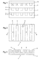
- Fig. 1 shows a top view of a first embodiment of the invention Device consisting of several catalyst disks 1, 10 is constructed.
- the catalyst disks 1, 10 are, for example, from catalyst powder by pressing produced to a shaped body and subsequent sintering.
- identical catalyst disks are used 1 with surface structure 9 joined together.
- a catalytic converter disc 10 without surface structure is the conclusion of last catalyst disk 1 provided.
- the catalyst disks 1, 10 are preferably connected to one another by press sintering.
- the surface structure 9 forms when joined together the catalyst disks 1, 10 between the top 2 and underside 3 of adjacent catalyst disks 1, 10 vertical Inlet and outlet channels 7, 8, which are parallel to each other are aligned.
- FIG. 2 shows a top view of a catalytic converter disk 1 of the type shown in FIG Fig. 1 shown device.
- the surface structure 9, the formed on an upper side 2 of the catalyst disk 1 can be done by exciting machining or by pressing the catalyst disc 1 are generated.
- the surface structure 9 comprises a plurality of channels 4 of the same structure, which interlocking and evenly arranged on the top 2 are distributed.
- Fig. 3 is to clarify the surface structure 9 shows a section through the catalyst disk 1 1 along the line A-A, the same Reference numerals designate the same elements.
- the equally structured channels 4 have an open and a closed end 6, 5. They are shaped so conically that the cross section from the open to the closed end rejuvenated.
- the channels 4 with open and closed at the top Channel ends form inlet channels 7 and channels 4 with channel ends open at the bottom and closed at the top Outlet channels 8.
- the inlet and outlet channels 7, 8 are alternating along the longitudinal direction of the catalyst disk 1 arranged.
- the number of inlet or outlet channels 7, 8 on a catalyst disk 1 is preferably odd.
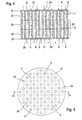
- Fig. 4 shows a section through a side view second embodiment of the device according to the invention.
- the device consists of an upper disc 21, a lower one Disc 22 and at least one central disc 23, all can have different strengths.
- the middle discs 23 consist of catalyst material and are, for example, from compressed and sintered catalyst powder manufactured.
- the upper disc 21 and lower disc 22 are preferably also made of catalyst material.
- the disks 21, 22, 23 can be connected by press sintering respectively.
- the middle disks 23 are parallel to the upper and lower Disk 21, 22 aligned.
- vertical bushings 24 are provided, which are evenly over the volume of the disk 23 are distributed.
- the implementations 24 of a plurality of middle disks 23 arranged one above the other are congruent with each other and form open on both sides Channel sections 25.
- the Channel sections open on both sides between the top and bottom of vertically arranged disks with corresponding Surface structure formed. These are on the top of the disc straight and parallel aligned recesses provided that spanned the full width of the disc extend.
- openings in the upper disk 21 and the lower disk 22 26 are arranged, which are not congruent with each other are. These can be done by drilling, punching or directly at Pressing the disks are generated.
- the openings 26 and Corresponding closed areas 27 limit the two sides open channel sections 25 of the middle disks 23. This become channels 4 with one-sided open and closed channel ends 6, 5 created, namely inlet and outlet channels 7, 8.
- the arrangement of the openings 25 is chosen so that inlet and alternate outlet channels 7, 8, i.e. on Inlet channel 7 is surrounded by several outlet channels 8 and vice versa.
- the arrangement of the openings 26 can also be designed such that the openings 26 when rotating the disc in the disc plane not congruent at least at a certain angle of rotation are mapped onto each other.
- One Arrangement of openings 26 can be for the upper and lower Disc 21, 22 a single type of disc can be used, wherein the function as an upper and lower disc 21, 22 through achieved correspondingly rotated installation of the washers becomes.
- FIG. 5 shows a top view of the second embodiment the device according to the invention.
- the one shown in Fig. 4 Section through the device according to the invention is along the Line A-A in Fig. 5 executed.
- the cross section of the device is circular in the present case, but as in the first embodiment also be angular.
- the openings 26 the upper disc 21 or the open channel ends 6 of the inlet channels 7 are visible from above, whereas the openings 26 of the lower disc 22 or the open channel ends 6 of the Outlet channels 8 are covered.
- Fig. 6 shows a section through a side view third embodiment of the device according to the invention.
- the device comprises an upper and a lower disk 21, 22, side walls 31 and tubes 30.
- the upper disc 21 and the lower washers 22 are spaced apart on the side walls 31 attached and together span a space 32.
- the tubes 30, which form the channels 4 with the same structure, are closed on one side.
- the tubes 30 are arranged inside the room 32 and so on the panes 21, 22 attached that the openings 26 with open ends 6th of the tubes 30 are aligned.
- the remaining interior is with catalyst material 33 filled in, e.g. by filling in a Catalyst powder.
- the disks 21, 22 and the tubes 30 are made made of porous material, the pore size being half so should be as small as the grain size of the catalyst material.
- the device according to the invention is double-walled Housing 34 attached.
- the space between the housing walls 34 is for thermal insulation with an insulating material 35, e.g. Expanded glass granules filled.
- Fastening means 36 are provided for connection.
- educts e.g. Methanol and water from above via a (not shown) Nozzle fed in fine spray. So that becomes a uniform distribution of the starting materials achieved.
- the educts are the powdered catalyst material or the disc pressed catalyst via the inlet channels 7 and Part also supplied via the upper disc 21.
- the reaction products In particular, hydrogen will be exhausts 8 collected and discharged.
- the flow of starting materials and products is in the Figg. 4 and 6 indicated by arrows.
- the device according to the invention is also particularly suitable as Cold start component, whereby by liquid dosing, gravity and good flowability positively influences the start time becomes.
- the embodiments of the device according to the invention can be used to build a multi-stage reactor.
- Suitable devices for producing an inventive 7 to 9, in turn same parts marked with identical reference numerals are.
- a hollow body 40 are in the axial direction spaced from each other an upper disc 21 and a lower one Disk 22 arranged, both disks 21, 22 each one Have a plurality of openings 26.
- the hollow body 40 can also be any other cross-sectional shapes, for example a square one Have cross-section.
- the would accordingly Disks 21, 22 have a square shape instead of a circular shape Have cross-sectional shape.
- molded bodies 41 are inserted with a positive fit, which are located in extend axially beyond the space 32.
- the remaining one Space between the two disks 21, 22 is filled with catalyst material 33 filled.
- the catalyst material pressed.
- both disks 21, 22 are movable relative to the hollow body 40, then on both discs 21, 22 act on a pressing force.
- the second Case has the advantage of more uniform pre-compression can be reached over the entire room 32. At the The discs 21, 22 can be pressed relative to the Move moldings 41.
- each channel 4 arise.
- inlet or Outlet channels 7, 8 must then still by suitable Measures in each case one channel end 5 in the area of the disks 21, 22 can be closed.
- each disc 21, 22 assigned a corresponding aperture are, the respective complementary openings 26 in the Close discs 21, 22.
- Simple tubular capillaries for example, can be used as shaped bodies 41 or steel round materials are used, which after the Pressing pulled out of the device in the axial direction become.
- the outer shape of this molded body 41 determines Here, the shape of the channels 4. It is therefore possible, in addition to the Circular shape also any other cross-sectional shapes for the To provide molded body 41, only the cross-sectional shape of the openings 26 to the cross-sectional shape of the molded bodies 41 must be coordinated. Furthermore, it is possible for molded articles 41 with different cross-sectional shape can be used. For example, a different shape in the edge area than in the central one Area. The cross-sectional shape of the molded body 41 can also be change in the axial direction.
- the shaped body at least in an axial Direction can be pulled through the openings 26.
- the shaped body for Position fixation have a stop (not shown), which, for example, when inserting on the space 32 facing away Side of one of the disks 21, 22 comes to rest.
- the molded bodies 41 can also be made of one material exist, which is suitable for the molded body 41 after the Melting melt.
- the material of the molded body 41 have a melting temperature at which the Catalyst material 33 is not damaged.
- a suitable diffusion layer can be applied, which when melting on the inner surfaces of the channels 4 remains and in the later operation of the device the diffusion rate the media from the channels 4 into the catalyst material 33 determined.
- the layer thickness can be advantageous here the diffusion layer over the axial extension of the Shaped body 41 vary.
- meltable moldings 41 also has the advantage that the possible Cross-sectional shapes of the molded body 41 less restricted is because the molded body 41 is not by the pressing corresponding openings 26 must be removed.
- the shaped bodies 41 can also have a shape opposite the shape of the openings 26 projecting cross-sectional shape. The size the openings 26 only have to be chosen so that the material the molded body 41 is still sufficient after pressing can be melted out.
- the disks 21, 22 themselves can also be made of catalyst material or from another material, for example steel, consist.
- the contact forces are preferably with a suitable one Stamp inserted on one or both sides.
- the hollow body 40 can be used as side wall 31, for example and thus part of the device for catalytic Form hydrogen production. Alternatively, the hollow body 40 but also be part of the manufacturing device, so that the catalyst body after pressing out of the hollow body 40 removed and later inserted into a suitable housing 34 becomes. If the hollow body 40 is used as the side wall 31, so this is preferably used to reduce weight finished device have the thinnest possible wall thickness. In this case, a thick-walled die 42 are provided during the pressing placed around the hollow body 40 and later removed can be. This die 42 preferably consists of two parts that are screwed together.
- a ring 42 may be provided for Filling the catalyst material 33 following the hollow body 40 .
- a device for hydrogen production can with a high proportion of catalyst based on the total mass the device, with reduced total volume and reduced Total mass can be produced.
- the manufacture easier because the number of individual parts required is relatively small and because there are fewer procedural steps requirement.
- a third embodiment according to FIG. 9 extend the shaped body 41 only in the axial direction a large part of the room 32. You will do this through openings 26 inserted in one of the two disks 21, 22 and however, do not extend completely to the opposite Disc 22, 21. Rather, the shaped bodies 41 are additional only by a suitable measure within the room 32 fixed in position, for example with the help of a arranged substantially centrally between the two disks 21, 22 Wire mesh 44 or the like.
- This method has the advantage that the respective closed end 5 of the channels 4 is formed directly by catalyst material, so that the discs 21, 22 only for the production, but not are required for the operation of the device and also on additional seals can be dispensed with.
Landscapes
- Chemical & Material Sciences (AREA)
- Organic Chemistry (AREA)
- Chemical Kinetics & Catalysis (AREA)
- General Health & Medical Sciences (AREA)
- Fluid Mechanics (AREA)
- Health & Medical Sciences (AREA)
- Physics & Mathematics (AREA)
- Engineering & Computer Science (AREA)
- Combustion & Propulsion (AREA)
- Inorganic Chemistry (AREA)
- Physical Or Chemical Processes And Apparatus (AREA)
- Catalysts (AREA)
- Hydrogen, Water And Hydrids (AREA)
Applications Claiming Priority (2)
| Application Number | Priority Date | Filing Date | Title |
|---|---|---|---|
| DE10028865A DE10028865C2 (de) | 2000-06-10 | 2000-06-10 | Vorrichtung zur katalytischen Wasserstofferzeugung aus Kohlenwasserstoffen |
| DE10028865 | 2000-06-10 |
Publications (2)
| Publication Number | Publication Date |
|---|---|
| EP1161987A2 true EP1161987A2 (fr) | 2001-12-12 |
| EP1161987A3 EP1161987A3 (fr) | 2003-05-21 |
Family
ID=7645419
Family Applications (1)
| Application Number | Title | Priority Date | Filing Date |
|---|---|---|---|
| EP01113877A Withdrawn EP1161987A3 (fr) | 2000-06-10 | 2001-06-07 | Dispositif et procédé de fabrication d'un dispositif pour la production catalytique d'hydrogène à partir d'hydrocarbures |
Country Status (3)
| Country | Link |
|---|---|
| US (2) | US6932948B2 (fr) |
| EP (1) | EP1161987A3 (fr) |
| DE (1) | DE10028865C2 (fr) |
Cited By (1)
| Publication number | Priority date | Publication date | Assignee | Title |
|---|---|---|---|---|
| CN115609997A (zh) * | 2022-11-14 | 2023-01-17 | 广东韩研活性炭科技股份有限公司 | 一种改性蜂窝炭成型方法 |
Families Citing this family (10)
| Publication number | Priority date | Publication date | Assignee | Title |
|---|---|---|---|---|
| US7922781B2 (en) | 2001-03-02 | 2011-04-12 | Chellappa Anand S | Hydrogen generation apparatus and method for using same |
| EP1372839A4 (fr) * | 2001-03-02 | 2006-11-29 | Mesofuel Inc | Appareil de production d'hydrogene a partir d'ammoniac et son procede d'utilisation |
| US7867300B2 (en) * | 2001-03-02 | 2011-01-11 | Intelligent Energy, Inc. | Ammonia-based hydrogen generation apparatus and method for using same |
| US7527661B2 (en) * | 2005-04-18 | 2009-05-05 | Intelligent Energy, Inc. | Compact devices for generating pure hydrogen |
| US8172913B2 (en) * | 2002-04-23 | 2012-05-08 | Vencill Thomas R | Array of planar membrane modules for producing hydrogen |
| US7192460B2 (en) * | 2003-02-28 | 2007-03-20 | Modine Manufacturing Company | Reformate cooling system and method for use in a fuel processing subsystem |
| US7648686B2 (en) * | 2004-04-05 | 2010-01-19 | Modine Manufacturing Company | Actively cooled exothermic reactor |
| DE102005034941B4 (de) * | 2005-07-22 | 2008-12-18 | J. Eberspächer GmbH & Co. KG | Reformer zur Erzeugung von Synthesegas |
| DE102012016561B4 (de) * | 2012-08-22 | 2019-05-16 | Airbus Defence and Space GmbH | Luftfahrzeug-Brennstoffzellensystem sowie Verwendung desselben |
| ES2985615T3 (es) * | 2016-02-08 | 2024-11-06 | Kt Kinetics Tech S P A | Reactor endotérmico de eficiencia mejorada para la producción de gas de síntesis con recuperación de calor flexible para satisfacer la baja generación de vapor de exportación |
Family Cites Families (12)
| Publication number | Priority date | Publication date | Assignee | Title |
|---|---|---|---|---|
| US3338681A (en) * | 1963-12-18 | 1967-08-29 | Union Carbide Corp | Apparatus for hydrogen generation |
| DE3302384A1 (de) * | 1983-01-25 | 1984-07-26 | Michael J. Lysaght | Plasmafilteraggregat zum abscheiden pathologischer plasmamolekuele |
| DE3542332A1 (de) * | 1985-11-29 | 1987-06-04 | Hutschenreuther | Verfahren und einrichtung zur herstellung von mit kanaelen versehenen presslingen aus pulverfoermiger formmasse, insbesondere keramischer formmasse stichwort: honeycomb |
| JP3032342B2 (ja) * | 1991-09-30 | 2000-04-17 | 株式会社ソディック | セラミックスハニカム構造体の製造方法 |
| DE4207905A1 (de) * | 1992-03-12 | 1993-09-16 | Bayer Ag | Festbettreaktoren mit kurzem katalysatorbett in stroemungsrichtung |
| JP3599370B2 (ja) * | 1994-05-23 | 2004-12-08 | 日本碍子株式会社 | 水素製造装置 |
| JPH10182102A (ja) * | 1996-12-19 | 1998-07-07 | Toshiba Corp | 改質装置及びそれを用いた燃料電池 |
| DE19743673C2 (de) * | 1997-10-02 | 2002-05-08 | Xcellsis Gmbh | Vorrichtung zur Wasserstofferzeugung aus Kohlenwasserstoffen und Verfahren zur Herstellung eines Katalysators |
| DE19832625C2 (de) * | 1998-07-21 | 2001-05-17 | Xcellsis Gmbh | Verfahren zur Herstellung eines Stapelreaktors und Stapelreaktor zur Wasserstofferzeugung aus Kohlenwasserstoffen |
| EP0992272A1 (fr) * | 1998-10-08 | 2000-04-12 | Corning Incorporated | Filtre poreux en forme d'un nid d'abeilles formé dans une presse |
| DE19944187A1 (de) * | 1999-09-15 | 2001-03-29 | Xcellsis Gmbh | Gaserzeugungssystem |
| DE10102726A1 (de) * | 2001-01-22 | 2002-08-22 | Vodafone Pilotentwicklung Gmbh | Reaktor |
-
2000
- 2000-06-10 DE DE10028865A patent/DE10028865C2/de not_active Expired - Fee Related
-
2001
- 2001-06-07 EP EP01113877A patent/EP1161987A3/fr not_active Withdrawn
- 2001-06-11 US US09/877,262 patent/US6932948B2/en not_active Expired - Fee Related
-
2005
- 2005-04-15 US US11/106,476 patent/US7494517B2/en not_active Expired - Fee Related
Cited By (1)
| Publication number | Priority date | Publication date | Assignee | Title |
|---|---|---|---|---|
| CN115609997A (zh) * | 2022-11-14 | 2023-01-17 | 广东韩研活性炭科技股份有限公司 | 一种改性蜂窝炭成型方法 |
Also Published As
| Publication number | Publication date |
|---|---|
| EP1161987A3 (fr) | 2003-05-21 |
| US6932948B2 (en) | 2005-08-23 |
| DE10028865C2 (de) | 2002-09-26 |
| US20050187101A1 (en) | 2005-08-25 |
| US20020021992A1 (en) | 2002-02-21 |
| DE10028865A1 (de) | 2002-04-18 |
| US7494517B2 (en) | 2009-02-24 |
Similar Documents
| Publication | Publication Date | Title |
|---|---|---|
| EP1426099B1 (fr) | Mélangeur statique et procédé | |
| DE2338070B2 (de) | Fraktionierungsvorrichtung | |
| EP1013331A1 (fr) | Module à membranes empilées pour la séparation sélective de gaz | |
| DE19753720C2 (de) | Vorrichtung zur selektiven katalytischen Oxidation von Kohlenmonoxid | |
| EP1161987A2 (fr) | Dispositif et procédé de fabrication d'un dispositif pour la production catalytique d'hydrogène à partir d'hydrocarbures | |
| EP1585589A2 (fr) | Module a membranes pour la separation de l'hydrogene et procede de fabrication dudit module | |
| DE69515773T2 (de) | Monolitischer, poröser Träger für Filtrationsmembrane | |
| DE2705123C2 (de) | Wärmetauscher und Verfahren zur Herstellung eines Wärmetauschers | |
| DE3026954A1 (de) | Waerme- und stoff-austauschapparat | |
| DE10010387A1 (de) | Kompositmembran und Kompositmembransystem sowie Verfahren zur Herstellung der Kompositmembranen | |
| DE60011724T2 (de) | Membran mit Honigwabenstruktur zur Gastrennung | |
| DE2508867B2 (de) | Vorrichtung zum Wärme- oder Stoffaustausch, die aus mehreren durch parallele Platten gebildete Austauschräumen besteht | |
| EP2058482A1 (fr) | Corps en nid d'abeille doté de faces frontales fissurées | |
| DE2102424A1 (de) | Flüssigkeitsverteiler für eine Stoffaustauschkolonne | |
| WO2002063636A2 (fr) | Reacteur | |
| DE10302693B3 (de) | Auflastvorrichtung | |
| EP0524926B1 (fr) | Echangeur de chaleur a metal fritte | |
| DE19904398B4 (de) | Lanze | |
| EP0423857B1 (fr) | Procédé pour la production d'une tôle en U avec des tôles disposées parallèlement l'une à l'autre, dispositif pour la mise en oeuvre du procédé | |
| DE102019134587B4 (de) | Wärmeübertrager und Adsorptionsmaschine | |
| DE3625117C1 (en) | Gas-flushing cone | |
| CH681281A5 (en) | Particle filter for sepg. process materials - comprises particulate porous elongated block with 1st channel for raw mixt. and 2nd channel for permeate | |
| WO2012010457A1 (fr) | Module destiné à séparer des mélanges de substances ainsi que procédé correspondant | |
| DE69323177T2 (de) | Anorganische filterstruktur mit mindestens einem integralen kanalnetzwerk für die zu filternde flüssigkeit und/oder für das genommene filtrat | |
| EP0678327A2 (fr) | Membrane pour la microfiltration de suspensions ou pour la séparation de gaz |
Legal Events
| Date | Code | Title | Description |
|---|---|---|---|
| PUAI | Public reference made under article 153(3) epc to a published international application that has entered the european phase |
Free format text: ORIGINAL CODE: 0009012 |
|
| AK | Designated contracting states |
Kind code of ref document: A2 Designated state(s): AT BE CH CY DE DK ES FI FR GB GR IE IT LI LU MC NL PT SE TR |
|
| AX | Request for extension of the european patent |
Free format text: AL;LT;LV;MK;RO;SI |
|
| RIN1 | Information on inventor provided before grant (corrected) |
Inventor name: PORTSCHER, MARKUS Inventor name: KLEIN, CHRISTIAN Inventor name: STEFANOVSKI, THOMAS Inventor name: CWIK, ROLAND Inventor name: BASS, JOHANNA, DR. |
|
| RAP1 | Party data changed (applicant data changed or rights of an application transferred) |
Owner name: BALLARD POWER SYSTEMS AG |
|
| PUAL | Search report despatched |
Free format text: ORIGINAL CODE: 0009013 |
|
| AK | Designated contracting states |
Designated state(s): AT BE CH CY DE DK ES FI FR GB GR IE IT LI LU MC NL PT SE TR |
|
| AX | Request for extension of the european patent |
Extension state: AL LT LV MK RO SI |
|
| AKX | Designation fees paid |
Designated state(s): DE FR GB IT |
|
| STAA | Information on the status of an ep patent application or granted ep patent |
Free format text: STATUS: THE APPLICATION IS DEEMED TO BE WITHDRAWN |
|
| 18D | Application deemed to be withdrawn |
Effective date: 20031122 |