EP1162101B1 - "A system for the active control of a motor vehicle differential" - Google Patents
"A system for the active control of a motor vehicle differential" Download PDFInfo
- Publication number
- EP1162101B1 EP1162101B1 EP01113382A EP01113382A EP1162101B1 EP 1162101 B1 EP1162101 B1 EP 1162101B1 EP 01113382 A EP01113382 A EP 01113382A EP 01113382 A EP01113382 A EP 01113382A EP 1162101 B1 EP1162101 B1 EP 1162101B1
- Authority
- EP
- European Patent Office
- Prior art keywords
- vehicle
- control
- reference value
- function
- yaw rate
- Prior art date
- Legal status (The legal status is an assumption and is not a legal conclusion. Google has not performed a legal analysis and makes no representation as to the accuracy of the status listed.)
- Expired - Lifetime
Links
Images

Classifications
-
- B—PERFORMING OPERATIONS; TRANSPORTING
- B60—VEHICLES IN GENERAL
- B60T—VEHICLE BRAKE CONTROL SYSTEMS OR PARTS THEREOF; BRAKE CONTROL SYSTEMS OR PARTS THEREOF, IN GENERAL; ARRANGEMENT OF BRAKING ELEMENTS ON VEHICLES IN GENERAL; PORTABLE DEVICES FOR PREVENTING UNWANTED MOVEMENT OF VEHICLES; VEHICLE MODIFICATIONS TO FACILITATE COOLING OF BRAKES
- B60T8/00—Arrangements for adjusting wheel-braking force to meet varying vehicular or ground-surface conditions, e.g. limiting or varying distribution of braking force
- B60T8/17—Using electrical or electronic regulation means to control braking
- B60T8/1755—Brake regulation specially adapted to control the stability of the vehicle, e.g. taking into account yaw rate or transverse acceleration in a curve
-
- B—PERFORMING OPERATIONS; TRANSPORTING
- B60—VEHICLES IN GENERAL
- B60K—ARRANGEMENT OR MOUNTING OF PROPULSION UNITS OR OF TRANSMISSIONS IN VEHICLES; ARRANGEMENT OR MOUNTING OF PLURAL DIVERSE PRIME-MOVERS IN VEHICLES; AUXILIARY DRIVES FOR VEHICLES; INSTRUMENTATION OR DASHBOARDS FOR VEHICLES; ARRANGEMENTS IN CONNECTION WITH COOLING, AIR INTAKE, GAS EXHAUST OR FUEL SUPPLY OF PROPULSION UNITS IN VEHICLES
- B60K23/00—Arrangement or mounting of control devices for vehicle transmissions, or parts thereof, not otherwise provided for
- B60K23/04—Arrangement or mounting of control devices for vehicle transmissions, or parts thereof, not otherwise provided for for differential gearing
-
- B—PERFORMING OPERATIONS; TRANSPORTING
- B60—VEHICLES IN GENERAL
- B60W—CONJOINT CONTROL OF VEHICLE SUB-UNITS OF DIFFERENT TYPE OR DIFFERENT FUNCTION; CONTROL SYSTEMS SPECIALLY ADAPTED FOR HYBRID VEHICLES; ROAD VEHICLE DRIVE CONTROL SYSTEMS FOR PURPOSES NOT RELATED TO THE CONTROL OF A PARTICULAR SUB-UNIT
- B60W30/00—Purposes of road vehicle drive control systems not related to the control of a particular sub-unit, e.g. of systems using conjoint control of vehicle sub-units
- B60W30/18—Propelling the vehicle
- B60W30/18009—Propelling the vehicle related to particular drive situations
- B60W30/18145—Cornering
-
- B—PERFORMING OPERATIONS; TRANSPORTING
- B60—VEHICLES IN GENERAL
- B60T—VEHICLE BRAKE CONTROL SYSTEMS OR PARTS THEREOF; BRAKE CONTROL SYSTEMS OR PARTS THEREOF, IN GENERAL; ARRANGEMENT OF BRAKING ELEMENTS ON VEHICLES IN GENERAL; PORTABLE DEVICES FOR PREVENTING UNWANTED MOVEMENT OF VEHICLES; VEHICLE MODIFICATIONS TO FACILITATE COOLING OF BRAKES
- B60T2201/00—Particular use of vehicle brake systems; Special systems using also the brakes; Special software modules within the brake system controller
- B60T2201/14—Electronic locking-differential
-
- B—PERFORMING OPERATIONS; TRANSPORTING
- B60—VEHICLES IN GENERAL
- B60T—VEHICLE BRAKE CONTROL SYSTEMS OR PARTS THEREOF; BRAKE CONTROL SYSTEMS OR PARTS THEREOF, IN GENERAL; ARRANGEMENT OF BRAKING ELEMENTS ON VEHICLES IN GENERAL; PORTABLE DEVICES FOR PREVENTING UNWANTED MOVEMENT OF VEHICLES; VEHICLE MODIFICATIONS TO FACILITATE COOLING OF BRAKES
- B60T2220/00—Monitoring, detecting driver behaviour; Signalling thereof; Counteracting thereof
- B60T2220/02—Driver type; Driving style; Driver adaptive features
-
- B—PERFORMING OPERATIONS; TRANSPORTING
- B60—VEHICLES IN GENERAL
- B60T—VEHICLE BRAKE CONTROL SYSTEMS OR PARTS THEREOF; BRAKE CONTROL SYSTEMS OR PARTS THEREOF, IN GENERAL; ARRANGEMENT OF BRAKING ELEMENTS ON VEHICLES IN GENERAL; PORTABLE DEVICES FOR PREVENTING UNWANTED MOVEMENT OF VEHICLES; VEHICLE MODIFICATIONS TO FACILITATE COOLING OF BRAKES
- B60T2260/00—Interaction of vehicle brake system with other systems
- B60T2260/02—Active Steering, Steer-by-Wire
-
- B—PERFORMING OPERATIONS; TRANSPORTING
- B60—VEHICLES IN GENERAL
- B60W—CONJOINT CONTROL OF VEHICLE SUB-UNITS OF DIFFERENT TYPE OR DIFFERENT FUNCTION; CONTROL SYSTEMS SPECIALLY ADAPTED FOR HYBRID VEHICLES; ROAD VEHICLE DRIVE CONTROL SYSTEMS FOR PURPOSES NOT RELATED TO THE CONTROL OF A PARTICULAR SUB-UNIT
- B60W50/00—Details of control systems for road vehicle drive control not related to the control of a particular sub-unit, e.g. process diagnostic or vehicle driver interfaces
- B60W2050/0001—Details of the control system
- B60W2050/0019—Control system elements or transfer functions
- B60W2050/0028—Mathematical models, e.g. for simulation
- B60W2050/0031—Mathematical model of the vehicle
-
- B—PERFORMING OPERATIONS; TRANSPORTING
- B60—VEHICLES IN GENERAL
- B60W—CONJOINT CONTROL OF VEHICLE SUB-UNITS OF DIFFERENT TYPE OR DIFFERENT FUNCTION; CONTROL SYSTEMS SPECIALLY ADAPTED FOR HYBRID VEHICLES; ROAD VEHICLE DRIVE CONTROL SYSTEMS FOR PURPOSES NOT RELATED TO THE CONTROL OF A PARTICULAR SUB-UNIT
- B60W2520/00—Input parameters relating to overall vehicle dynamics
- B60W2520/10—Longitudinal speed
- B60W2520/105—Longitudinal acceleration
-
- B—PERFORMING OPERATIONS; TRANSPORTING
- B60—VEHICLES IN GENERAL
- B60W—CONJOINT CONTROL OF VEHICLE SUB-UNITS OF DIFFERENT TYPE OR DIFFERENT FUNCTION; CONTROL SYSTEMS SPECIALLY ADAPTED FOR HYBRID VEHICLES; ROAD VEHICLE DRIVE CONTROL SYSTEMS FOR PURPOSES NOT RELATED TO THE CONTROL OF A PARTICULAR SUB-UNIT
- B60W2520/00—Input parameters relating to overall vehicle dynamics
- B60W2520/12—Lateral speed
- B60W2520/125—Lateral acceleration
-
- B—PERFORMING OPERATIONS; TRANSPORTING
- B60—VEHICLES IN GENERAL
- B60W—CONJOINT CONTROL OF VEHICLE SUB-UNITS OF DIFFERENT TYPE OR DIFFERENT FUNCTION; CONTROL SYSTEMS SPECIALLY ADAPTED FOR HYBRID VEHICLES; ROAD VEHICLE DRIVE CONTROL SYSTEMS FOR PURPOSES NOT RELATED TO THE CONTROL OF A PARTICULAR SUB-UNIT
- B60W2520/00—Input parameters relating to overall vehicle dynamics
- B60W2520/14—Yaw
-
- B—PERFORMING OPERATIONS; TRANSPORTING
- B60—VEHICLES IN GENERAL
- B60W—CONJOINT CONTROL OF VEHICLE SUB-UNITS OF DIFFERENT TYPE OR DIFFERENT FUNCTION; CONTROL SYSTEMS SPECIALLY ADAPTED FOR HYBRID VEHICLES; ROAD VEHICLE DRIVE CONTROL SYSTEMS FOR PURPOSES NOT RELATED TO THE CONTROL OF A PARTICULAR SUB-UNIT
- B60W2540/00—Input parameters relating to occupants
- B60W2540/18—Steering angle
Definitions
- the present invention relates to a system for the active control of a motor vehicle differential.
- the subject of the invention is a system for controlling a differential comprising an inlet shaft intended to transmit torque to two output shafts or half-shafts associated with respective wheels of the motor vehicle, and selective coupling means controllable by means of corresponding actuator devices to modify the division of torque between said half-shafts.
- One object of the present invention is to provide a system for controlling such a differential, which makes it possible to increase the stability of the motor vehicle and give optimum control of the division of the load between the inner wheel and the outer wheel on bends.
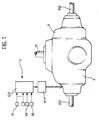
- the differential D comprises an inlet shaft M, intended to transmit torque from the engine (not illustrated) to two output shafts or half-shafts (AS1 and AS2) associated with respective driven wheels (also not illustrated) of the motor vehicle.
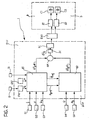
- the differential D comprises a plurality of friction clutches (not illustrated in Figure 1 but schematically shown in Figure 2 indicated there C1 and C2) selectively controllable by use of corresponding actuator devices (also not illustrated in Figure 1, but schematically shown in Figure 2 where they are indicated A1 and A2).
- actuator devices are, for example, hydraulic cylinders piloted by an electro-hydraulic unit such as that schematically shown in Figs. 1 and 2 where it is indicated EHU.
- This electro-hydraulic unit is in turn controlled by a control system generally indicated 1 in Figs. 1 and 2.
- This control system can for example comprise an electronic unit ECU having a plurality of inputs which are provided with respective input signals representative of the values assumed by corresponding quantities.
- These input signals can be provided to the unit ECU by suitable sensors installed on board the motor vehicle, and/or by other electronic control units installed on board the motor vehicle and connected to the unit ECU of interest here by means of a line or communication network according to techniques known per se.
- the signals applied to the inputs of the unit ECU will be assumed to be provided from corresponding sensors or transducers.
- signals provided from sensors S1 to S5 are applied to the unit ECU of the control system 1 shown here.
- the sensors S1 and S2 provide the unit ECU with respective signals indicative of the steering angle ⁇ (the angle of rotation of the steering wheel) and the speed V of the vehicle.
- the sensors S3 and S5 provide the unit ECU with respective signals indicative of the longitudinal acceleration a x and transverse acceleration a y respectively of the vehicle.
- Sensor S4 provides the unit ECU with a signal indicative of the yaw rate ⁇ .
- Sensor S4 is for example a so-called gyroscope or gyrometer.
- the unit ECU comprises two main processor blocks B1 and B2 which are connected to sensors S1-S3 and, respectively, the sensors S4 and S5.
- the processor blocks B1 and B2 are arranged to generate respective yaw torque control signals ⁇ T yo1 and ⁇ T ycl , which are added in a summing device SM which, following a filter ZC, provides an output control signal ⁇ T y to a driver circuit DC which, via the electro-hydraulic unit EHU controls the actuators A1 and A2 of the differential D.
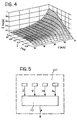
- the block B1 comprises a memory M1 in which are stored pre-determined reference values of the yaw rate ⁇ ref, addressable on the basis of the instantaneous values of the steering angle ⁇ and the vehicle speed V.
- reference values of the yaw rate are tabulated as shown in the three dimensional graph of Figure 4.
- the memory M1 is connected to a processor section F1 which equally receives signals indicative of the steering angle ⁇ and the vehicle speed V.
- the processor section F1 is arranged to generate a first yaw torque control signal ⁇ T y1 on the basis of a pre-determined mathematical model of the behaviour of the motor vehicle, and as a function of the value of ⁇ ref .
- the block B1 further includes a second processor section F2 which receives the signal provided by the sensor S3 indicative of the longitudinal acceleration a x of the motor vehicle, as well as a lateral or transverse acceleration reference value a yref .
- This reference value a yref is provided at the output of a multiplier device P the inputs of which receive the signals indicative of the motor vehicle speed V and the reference value ⁇ ref of the yaw rate.
- the signal indicative of the longitudinal acceleration a x can be obtained by differentiating the signal provided from the sensor S2 which is indicative of the motor vehicle speed V.
- the processor section F2 is arranged to generate a second yaw torque control signal ⁇ T y2 in dependence on a pre-determined function of the longitudinal acceleration a x of the vehicle.
- the signal ⁇ T y2 is for example proportional to the product of the longitudinal acceleration a x and the lateral acceleration reference value a yref .
- the signals ⁇ T y1 and ⁇ T y2 are delivered to the inputs of a summing device SM1 at the output of which there is therefore available a sum signal ⁇ T yo1 .
- the above-described processor block B1 performs an open loop control on the yaw torque acting on the motor vehicle whilst, as will be seen hereinafter, the processor block B2 performs a closed loop control.
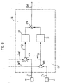
- the memory M1 can store yaw rate reference values ⁇ ref not just as a function of the steering angle ⁇ and the vehicle speed V, but rather as a function also of the value of the co-efficient of friction ⁇ between the tyres of the motor vehicle and the road surface as calculated by an estimator device generally indicated EST in Figs. 2, 3 and 5.
- the estimator EST comprises a processor section F3 arranged to calculate, or rather estimate, the value of ⁇ on the basis of values of steering angle ⁇ , the yaw rate ⁇ , the speed ⁇ i of the motor vehicle wheels, and the longitudinal acceleration a x.
- the reference values ⁇ ref in the memory M1 can also be stored as a function of the values of a further parameter, represented by an understeer index US computed by a further processor section F4 taking into account the understeer gradient desired by the user and set thereby by means of a setting device indicated I in Figures 2 and 3.
- the processor section F4 can be arranged to recognise, on the basis of the values assumed by a plurality of input signals, the driving "style" of the user in a continuous learning process.
- the processor block B2 receives signals indicative of the yaw rate ⁇ and the lateral acceleration a y . This block also receives from the processor block B1 the lateral acceleration reference value a yref and the yaw rate reference value ⁇ ref .
- the outputs from blocks F5 and F6 lead to a summing unit SM4 the output of which represents the control signal ⁇ T yc1 .
- the system described above allows an optimum control of the stability of the vehicle and control of the division of the torque when the vehicle is travelling in the bend with a progressive transfer of torque from the inner wheels facing the centre of the curve to the outer wheels.
- the system further allows understeer behaviour with the possibility of the user deciding the magnitude of the understeer effect.
Landscapes
- Engineering & Computer Science (AREA)
- Transportation (AREA)
- Mechanical Engineering (AREA)
- Chemical & Material Sciences (AREA)
- Combustion & Propulsion (AREA)
- Automation & Control Theory (AREA)
- Arrangement And Mounting Of Devices That Control Transmission Of Motive Force (AREA)
- Retarders (AREA)
- Steering Control In Accordance With Driving Conditions (AREA)
- Arrangement And Driving Of Transmission Devices (AREA)
Applications Claiming Priority (3)
| Application Number | Priority Date | Filing Date | Title |
|---|---|---|---|
| IT2000TO000528A IT1320394B1 (it) | 2000-06-05 | 2000-06-05 | Sistema per il controllo attivo di un differenziale di un autoveicolo. |
| ITTO200528 | 2000-06-05 | ||
| ITTO000528 | 2000-06-05 |
Publications (3)
| Publication Number | Publication Date |
|---|---|
| EP1162101A2 EP1162101A2 (en) | 2001-12-12 |
| EP1162101A3 EP1162101A3 (en) | 2003-06-18 |
| EP1162101B1 true EP1162101B1 (en) | 2007-07-04 |
Family
ID=11457784
Family Applications (1)
| Application Number | Title | Priority Date | Filing Date |
|---|---|---|---|
| EP01113382A Expired - Lifetime EP1162101B1 (en) | 2000-06-05 | 2001-06-01 | "A system for the active control of a motor vehicle differential" |
Country Status (6)
| Country | Link |
|---|---|
| US (1) | US6393351B2 (it) |
| EP (1) | EP1162101B1 (it) |
| BR (1) | BR0105877A (it) |
| DE (1) | DE60129188T2 (it) |
| ES (1) | ES2287056T3 (it) |
| IT (1) | IT1320394B1 (it) |
Families Citing this family (23)
| Publication number | Priority date | Publication date | Assignee | Title |
|---|---|---|---|---|
| KR100789519B1 (ko) * | 2001-11-14 | 2007-12-28 | 씨.알.에프. 소시에타 콘소르티레 페르 아치오니 | 차량 차동장치의 능동 제어를 위한 시스템 |
| JP2003312289A (ja) * | 2002-04-23 | 2003-11-06 | Toyoda Mach Works Ltd | 4輪駆動車 |
| JP3868848B2 (ja) * | 2002-05-23 | 2007-01-17 | 三菱電機株式会社 | 車両状態検出装置 |
| DE10245035A1 (de) * | 2002-09-26 | 2004-04-08 | Dr.Ing.H.C. F. Porsche Ag | Verfahren zur Regelung des Fahrverhaltens mittels Einflussnahme zur Vermeidung des Untersteuerns |
| US7010409B2 (en) * | 2003-02-26 | 2006-03-07 | Ford Global Technologies, Llc | Reference signal generator for an integrated sensing system |
| DE502004008154D1 (de) | 2003-05-08 | 2008-11-13 | Continental Teves Ag & Co Ohg | Verfahren und vorrichtung zum regeln der fahrdynamik eines fahrzeugs |
| JP4519439B2 (ja) * | 2003-10-08 | 2010-08-04 | 富士重工業株式会社 | 車両挙動検出装置、及び車両挙動検出装置を用いた車両挙動制御装置 |
| DE102004004871A1 (de) * | 2004-01-30 | 2005-08-18 | Gkn Driveline International Gmbh | Verfahren und Anordnung zur Steuerung einer Sperrkupplung für ein Achsdifferential eines Kraftfahrzeugs |
| US7953536B2 (en) * | 2005-07-29 | 2011-05-31 | GM Global Technology Operations LLC | Inertial sensor software architecture security method |
| US7455142B2 (en) * | 2005-12-05 | 2008-11-25 | Honda Motor Co., Ltd. | Scaling of side-to-side torque bias to improve cornering in a programmable four wheel drive system |
| US8073607B2 (en) * | 2008-01-28 | 2011-12-06 | GM Global Technology Operations LLC | Method for populating motor vehicle yaw gain tables for use in an electronic stability control system |
| US20110269595A1 (en) | 2010-04-30 | 2011-11-03 | American Axle & Manufacturing Inc. | Control strategy for operating a locking differential |
| WO2016011096A1 (en) | 2014-07-16 | 2016-01-21 | Dana Automotives Systems Group, LLC | A drive unit with twin side shaft torque coupling |
| DE102016110791A1 (de) | 2015-06-15 | 2016-12-15 | Steering Solutions Ip Holding Corporation | Gestensteuerung für ein einfahrbares Lenkrad |
| US10496102B2 (en) | 2016-04-11 | 2019-12-03 | Steering Solutions Ip Holding Corporation | Steering system for autonomous vehicle |
| DE102017108692B4 (de) * | 2016-04-25 | 2024-09-26 | Steering Solutions Ip Holding Corporation | Steuerung einer elektrischen Servolenkung unter Verwendung von Systemzustandsvorhersagen |
| US10384708B2 (en) | 2016-09-12 | 2019-08-20 | Steering Solutions Ip Holding Corporation | Intermediate shaft assembly for steer-by-wire steering system |
| US10399591B2 (en) | 2016-10-03 | 2019-09-03 | Steering Solutions Ip Holding Corporation | Steering compensation with grip sensing |
| US10310605B2 (en) | 2016-11-15 | 2019-06-04 | Steering Solutions Ip Holding Corporation | Haptic feedback for steering system controls |
| US10780915B2 (en) | 2016-12-07 | 2020-09-22 | Steering Solutions Ip Holding Corporation | Vehicle steering system having a user experience based automated driving to manual driving transition system and method |
| US10197144B2 (en) | 2017-01-20 | 2019-02-05 | Dana Heavy Vehicle Systems Group, Llc | Drive unit with torque vectoring and an axle disconnect and reconnect mechanism |
| US10449927B2 (en) | 2017-04-13 | 2019-10-22 | Steering Solutions Ip Holding Corporation | Steering system having anti-theft capabilities |
| CN111186438B (zh) * | 2020-01-16 | 2021-06-25 | 北京中科怡驰科技有限公司 | 一种弯道障碍车辆过滤方法 |
Family Cites Families (9)
| Publication number | Priority date | Publication date | Assignee | Title |
|---|---|---|---|---|
| JPH0725320B2 (ja) * | 1986-10-13 | 1995-03-22 | 日産自動車株式会社 | 車両用実舵角制御装置 |
| DE4114165C2 (de) * | 1990-05-02 | 1995-04-20 | Nissan Motor | Lenksteuervorrichtung für ein Räderfahrzeug |
| IT1250886B (it) | 1991-12-20 | 1995-04-21 | Fiat Ricerche | Sistema per il controllo della ripartizione della coppia motrice tra le ruote di uno stesso assale di un veicolo. |
| US5375097A (en) * | 1993-06-29 | 1994-12-20 | Reddy; Chitranjan N. | Segmented bus architecture for improving speed in integrated circuit memories |
| US5417298A (en) * | 1993-07-07 | 1995-05-23 | Honda Giken Kohyo Kabushiki Kaisha | Torque distribution control apparatus for vehicle |
| IT1261136B (it) | 1993-12-29 | 1996-05-09 | Fiat Ricerche | Differenziale per autoveicolo con sistema per il controllo della ripartizione della coppia motrice, a comando elettronico. |
| JPH07323859A (ja) * | 1994-06-01 | 1995-12-12 | Nissan Motor Co Ltd | 車両運動制御装置 |
| GB2323940B (en) * | 1994-06-27 | 1999-01-20 | Fuji Heavy Ind Ltd | Vehicle driving torque distribution control system and method |
| JPH10194001A (ja) * | 1997-01-16 | 1998-07-28 | Tochigi Fuji Ind Co Ltd | デファレンシャル装置 |
-
2000
- 2000-06-05 IT IT2000TO000528A patent/IT1320394B1/it active
-
2001
- 2001-06-01 DE DE60129188T patent/DE60129188T2/de not_active Expired - Lifetime
- 2001-06-01 ES ES01113382T patent/ES2287056T3/es not_active Expired - Lifetime
- 2001-06-01 EP EP01113382A patent/EP1162101B1/en not_active Expired - Lifetime
- 2001-06-04 US US09/871,728 patent/US6393351B2/en not_active Expired - Lifetime
- 2001-11-14 BR BR0105877-0A patent/BR0105877A/pt not_active Application Discontinuation
Also Published As
| Publication number | Publication date |
|---|---|
| IT1320394B1 (it) | 2003-11-26 |
| BR0105877A (pt) | 2002-04-16 |
| ITTO20000528A0 (it) | 2000-06-05 |
| EP1162101A3 (en) | 2003-06-18 |
| DE60129188D1 (de) | 2007-08-16 |
| ES2287056T3 (es) | 2007-12-16 |
| DE60129188T2 (de) | 2008-03-13 |
| US20020016661A1 (en) | 2002-02-07 |
| EP1162101A2 (en) | 2001-12-12 |
| ITTO20000528A1 (it) | 2001-12-05 |
| US6393351B2 (en) | 2002-05-21 |
Similar Documents
| Publication | Publication Date | Title |
|---|---|---|
| US6393351B2 (en) | System for the active control of a motor vehicle differential | |
| US6892123B2 (en) | Unified control of vehicle dynamics using force and moment control | |
| Kim et al. | Vehicle stability enhancement of four-wheel-drive hybrid electric vehicle using rear motor control | |
| EP0225180B1 (en) | Brake control system on turning of motor vehicle | |
| CN101395025B (zh) | 使用电子控制止滑差动机构的稳定性增强牵引与横摆控制 | |
| US8244435B2 (en) | Method and system for determining an optimal steering angle in understeer situations in a vehicle | |
| JP5859038B2 (ja) | 四輪操舵車両のトルク分配制御方法 | |
| US8788147B2 (en) | Method for determining a toothed rack force for a steering device in a vehicle | |
| US6968261B2 (en) | Method and apparatus for vehicle stability enhancement system | |
| US6865468B2 (en) | Method and apparatus for vehicle stability enhancement system | |
| US6027183A (en) | Vehicle dynamics control system | |
| JP2004505855A (ja) | 路上走行車においてヨー・ダイナミックスおよび横方向ダイナミックスを制御するための方法 | |
| EP4129785B1 (en) | Method for determining an optimized torque distribution to the drive wheels of a road vehicle and relative road vehicle | |
| EP1522475B1 (en) | Vehicle-behavior detecting apparatus and vehicle-behavior controlling apparatus | |
| EP1989093B1 (en) | Vehicular behavior controller | |
| CN112969627A (zh) | 用于组合的液压辅助和电力辅助的转向的方法和系统 | |
| CN102971201B (zh) | 用于测定车辆中转向装置的齿条力的方法 | |
| GB2428755A (en) | Vehicle traction control using an active limited slip differential | |
| KR100789519B1 (ko) | 차량 차동장치의 능동 제어를 위한 시스템 | |
| JP4058260B2 (ja) | 車両用差動装置のアクティブ制御システム | |
| JPH0268226A (ja) | 4輪駆動車の駆動力制御方法及び装置 | |
| JP4155246B2 (ja) | 車輌の運動制御装置 | |
| JP2894399B2 (ja) | 駆動力配分連動式後輪操舵装置付き車両 | |
| CN121316973A (zh) | 转向控制方法、装置、设备及存储介质 | |
| JPH04159134A (ja) | 車両用動力伝達装置 |
Legal Events
| Date | Code | Title | Description |
|---|---|---|---|
| PUAI | Public reference made under article 153(3) epc to a published international application that has entered the european phase |
Free format text: ORIGINAL CODE: 0009012 |
|
| AK | Designated contracting states |
Kind code of ref document: A2 Designated state(s): AT BE CH CY DE DK ES FI FR GB GR IE IT LI LU MC NL PT SE TR |
|
| AX | Request for extension of the european patent |
Free format text: AL;LT;LV;MK;RO;SI |
|
| PUAL | Search report despatched |
Free format text: ORIGINAL CODE: 0009013 |
|
| AK | Designated contracting states |
Designated state(s): AT BE CH CY DE DK ES FI FR GB GR IE IT LI LU MC NL PT SE TR |
|
| AX | Request for extension of the european patent |
Extension state: AL LT LV MK RO SI |
|
| 17P | Request for examination filed |
Effective date: 20031205 |
|
| AKX | Designation fees paid |
Designated state(s): DE ES FR GB IT SE |
|
| 17Q | First examination report despatched |
Effective date: 20040216 |
|
| GRAP | Despatch of communication of intention to grant a patent |
Free format text: ORIGINAL CODE: EPIDOSNIGR1 |
|
| GRAS | Grant fee paid |
Free format text: ORIGINAL CODE: EPIDOSNIGR3 |
|
| GRAA | (expected) grant |
Free format text: ORIGINAL CODE: 0009210 |
|
| AK | Designated contracting states |
Kind code of ref document: B1 Designated state(s): DE ES FR GB IT SE |
|
| REG | Reference to a national code |
Ref country code: GB Ref legal event code: FG4D |
|
| REG | Reference to a national code |
Ref country code: SE Ref legal event code: TRGR |
|
| REF | Corresponds to: |
Ref document number: 60129188 Country of ref document: DE Date of ref document: 20070816 Kind code of ref document: P |
|
| ET | Fr: translation filed | ||
| REG | Reference to a national code |
Ref country code: ES Ref legal event code: FG2A Ref document number: 2287056 Country of ref document: ES Kind code of ref document: T3 |
|
| PLBE | No opposition filed within time limit |
Free format text: ORIGINAL CODE: 0009261 |
|
| STAA | Information on the status of an ep patent application or granted ep patent |
Free format text: STATUS: NO OPPOSITION FILED WITHIN TIME LIMIT |
|
| 26N | No opposition filed |
Effective date: 20080407 |
|
| PGFP | Annual fee paid to national office [announced via postgrant information from national office to epo] |
Ref country code: ES Payment date: 20110620 Year of fee payment: 11 Ref country code: SE Payment date: 20110622 Year of fee payment: 11 |
|
| PGFP | Annual fee paid to national office [announced via postgrant information from national office to epo] |
Ref country code: GB Payment date: 20110620 Year of fee payment: 11 |
|
| REG | Reference to a national code |
Ref country code: SE Ref legal event code: EUG |
|
| GBPC | Gb: european patent ceased through non-payment of renewal fee |
Effective date: 20120601 |
|
| PG25 | Lapsed in a contracting state [announced via postgrant information from national office to epo] |
Ref country code: SE Free format text: LAPSE BECAUSE OF NON-PAYMENT OF DUE FEES Effective date: 20120602 |
|
| PG25 | Lapsed in a contracting state [announced via postgrant information from national office to epo] |
Ref country code: GB Free format text: LAPSE BECAUSE OF NON-PAYMENT OF DUE FEES Effective date: 20120601 |
|
| REG | Reference to a national code |
Ref country code: ES Ref legal event code: FD2A Effective date: 20131021 |
|
| PG25 | Lapsed in a contracting state [announced via postgrant information from national office to epo] |
Ref country code: ES Free format text: LAPSE BECAUSE OF NON-PAYMENT OF DUE FEES Effective date: 20120602 |
|
| REG | Reference to a national code |
Ref country code: FR Ref legal event code: PLFP Year of fee payment: 16 |
|
| REG | Reference to a national code |
Ref country code: FR Ref legal event code: PLFP Year of fee payment: 17 |
|
| REG | Reference to a national code |
Ref country code: FR Ref legal event code: PLFP Year of fee payment: 18 |
|
| PGFP | Annual fee paid to national office [announced via postgrant information from national office to epo] |
Ref country code: FR Payment date: 20190701 Year of fee payment: 19 Ref country code: DE Payment date: 20190830 Year of fee payment: 19 |
|
| PGFP | Annual fee paid to national office [announced via postgrant information from national office to epo] |
Ref country code: IT Payment date: 20200609 Year of fee payment: 20 |
|
| REG | Reference to a national code |
Ref country code: DE Ref legal event code: R119 Ref document number: 60129188 Country of ref document: DE |
|
| PG25 | Lapsed in a contracting state [announced via postgrant information from national office to epo] |
Ref country code: FR Free format text: LAPSE BECAUSE OF NON-PAYMENT OF DUE FEES Effective date: 20200630 |
|
| PG25 | Lapsed in a contracting state [announced via postgrant information from national office to epo] |
Ref country code: DE Free format text: LAPSE BECAUSE OF NON-PAYMENT OF DUE FEES Effective date: 20210101 |