EP1162140A2 - Vorrichtung und Verfahren zum Abgeben von Pulvern - Google Patents
Vorrichtung und Verfahren zum Abgeben von Pulvern Download PDFInfo
- Publication number
- EP1162140A2 EP1162140A2 EP20010113426 EP01113426A EP1162140A2 EP 1162140 A2 EP1162140 A2 EP 1162140A2 EP 20010113426 EP20010113426 EP 20010113426 EP 01113426 A EP01113426 A EP 01113426A EP 1162140 A2 EP1162140 A2 EP 1162140A2
- Authority
- EP
- European Patent Office
- Prior art keywords
- dispensing
- powder
- container
- chamber
- valve
- Prior art date
- Legal status (The legal status is an assumption and is not a legal conclusion. Google has not performed a legal analysis and makes no representation as to the accuracy of the status listed.)
- Granted
Links
- 239000000843 powder Substances 0.000 title claims abstract description 128
- 238000000034 method Methods 0.000 title claims description 11
- 239000011148 porous material Substances 0.000 claims description 10
- 239000002184 metal Substances 0.000 claims description 8
- 229910052751 metal Inorganic materials 0.000 claims description 8
- 239000000203 mixture Substances 0.000 claims description 7
- 239000007789 gas Substances 0.000 description 24
- 239000000463 material Substances 0.000 description 14
- 239000000428 dust Substances 0.000 description 7
- 238000010276 construction Methods 0.000 description 5
- XKRFYHLGVUSROY-UHFFFAOYSA-N Argon Chemical compound [Ar] XKRFYHLGVUSROY-UHFFFAOYSA-N 0.000 description 4
- IJGRMHOSHXDMSA-UHFFFAOYSA-N Atomic nitrogen Chemical compound N#N IJGRMHOSHXDMSA-UHFFFAOYSA-N 0.000 description 4
- 230000007423 decrease Effects 0.000 description 4
- 238000005243 fluidization Methods 0.000 description 3
- 230000036541 health Effects 0.000 description 3
- 229910001220 stainless steel Inorganic materials 0.000 description 3
- 239000000126 substance Substances 0.000 description 3
- 229910052786 argon Inorganic materials 0.000 description 2
- 229910010293 ceramic material Inorganic materials 0.000 description 2
- 230000001419 dependent effect Effects 0.000 description 2
- 239000007769 metal material Substances 0.000 description 2
- 150000002739 metals Chemical class 0.000 description 2
- 229910052757 nitrogen Inorganic materials 0.000 description 2
- 239000002245 particle Substances 0.000 description 2
- 239000000047 product Substances 0.000 description 2
- 239000002699 waste material Substances 0.000 description 2
- 239000000654 additive Substances 0.000 description 1
- 230000002411 adverse Effects 0.000 description 1
- 239000003570 air Substances 0.000 description 1
- QVGXLLKOCUKJST-UHFFFAOYSA-N atomic oxygen Chemical compound [O] QVGXLLKOCUKJST-UHFFFAOYSA-N 0.000 description 1
- 239000007795 chemical reaction product Substances 0.000 description 1
- 238000004140 cleaning Methods 0.000 description 1
- 238000011109 contamination Methods 0.000 description 1
- 239000002537 cosmetic Substances 0.000 description 1
- 238000009826 distribution Methods 0.000 description 1
- 239000003814 drug Substances 0.000 description 1
- 230000009881 electrostatic interaction Effects 0.000 description 1
- 239000000835 fiber Substances 0.000 description 1
- 235000013305 food Nutrition 0.000 description 1
- 230000013011 mating Effects 0.000 description 1
- 230000007246 mechanism Effects 0.000 description 1
- 238000012986 modification Methods 0.000 description 1
- 230000004048 modification Effects 0.000 description 1
- 230000003647 oxidation Effects 0.000 description 1
- 238000007254 oxidation reaction Methods 0.000 description 1
- 239000001301 oxygen Substances 0.000 description 1
- 229910052760 oxygen Inorganic materials 0.000 description 1
- 230000035699 permeability Effects 0.000 description 1
- 239000002994 raw material Substances 0.000 description 1
- 230000008439 repair process Effects 0.000 description 1
- 238000005476 soldering Methods 0.000 description 1
- -1 space concerns Substances 0.000 description 1
- 239000010935 stainless steel Substances 0.000 description 1
- 238000013022 venting Methods 0.000 description 1
- 238000003466 welding Methods 0.000 description 1
Images



Classifications
-
- B—PERFORMING OPERATIONS; TRANSPORTING
- B65—CONVEYING; PACKING; STORING; HANDLING THIN OR FILAMENTARY MATERIAL
- B65B—MACHINES, APPARATUS OR DEVICES FOR, OR METHODS OF, PACKAGING ARTICLES OR MATERIALS; UNPACKING
- B65B1/00—Packaging fluent solid material, e.g. powders, granular or loose fibrous material, loose masses of small articles, in individual containers or receptacles, e.g. bags, sacks, boxes, cartons, cans, or jars
- B65B1/04—Methods of, or means for, filling the material into the containers or receptacles
- B65B1/16—Methods of, or means for, filling the material into the containers or receptacles by pneumatic means, e.g. by suction
-
- Y—GENERAL TAGGING OF NEW TECHNOLOGICAL DEVELOPMENTS; GENERAL TAGGING OF CROSS-SECTIONAL TECHNOLOGIES SPANNING OVER SEVERAL SECTIONS OF THE IPC; TECHNICAL SUBJECTS COVERED BY FORMER USPC CROSS-REFERENCE ART COLLECTIONS [XRACs] AND DIGESTS
- Y10—TECHNICAL SUBJECTS COVERED BY FORMER USPC
- Y10T—TECHNICAL SUBJECTS COVERED BY FORMER US CLASSIFICATION
- Y10T137/00—Fluid handling
- Y10T137/8593—Systems
- Y10T137/87917—Flow path with serial valves and/or closures
- Y10T137/87925—Separable flow path section, valve or closure in each
-
- Y—GENERAL TAGGING OF NEW TECHNOLOGICAL DEVELOPMENTS; GENERAL TAGGING OF CROSS-SECTIONAL TECHNOLOGIES SPANNING OVER SEVERAL SECTIONS OF THE IPC; TECHNICAL SUBJECTS COVERED BY FORMER USPC CROSS-REFERENCE ART COLLECTIONS [XRACs] AND DIGESTS
- Y10—TECHNICAL SUBJECTS COVERED BY FORMER USPC
- Y10T—TECHNICAL SUBJECTS COVERED BY FORMER US CLASSIFICATION
- Y10T137/00—Fluid handling
- Y10T137/8593—Systems
- Y10T137/87917—Flow path with serial valves and/or closures
- Y10T137/87925—Separable flow path section, valve or closure in each
- Y10T137/87933—Common joint and valve seat faces, or sections joined by closing members
Definitions
- This invention relates to the dispensing of powders. More particularly, this invention relates to apparatus and methods for dispensing powders.
- Dispensing systems are used to dispense powders from a container into a receiving vessel.
- the container is typically attachable to the receiving vessel via a gasket arrangement during the dispensing operation.
- a dispensing valve controls the discharge of the powder from the container during dispensing operations.
- the gasket arrangement does not fit correctly, or if the container and receiving vessel are not perfectly aligned, then the powder tends to leak into the dispensing facility. This leakage of the powder can occur during dispensing, or after dispensing has been completed and the container and receiving vessel have been separated from each other.
- the leaked powder may cause health and safety concerns for persons in the facility.
- the leaked powder material can create housekeeping problems and results in material waste.
- This invention provides a dispensing system for dispensing powders that can satisfy the above-described needs.
- This invention separately provides a dispensing system that can be used to dispense powders with substantially complete containment of the powders.
- This invention separately provides a dispensing system that can dispense powders at a suitably high dispensing rate.
- This invention separately provides a dispensing system that has a simplified construction and is easy to operate.
- This invention separately provides a dispensing system that is mobile.
- This invention separately provides methods of dispensing powders.
- Exemplary embodiments of the systems for containing and dispensing powders comprise a dispensing container including a chamber having an outlet.
- a fluidizing system fluidizes the powder in the chamber to enhance the flow of the powder.
- the dispensing system comprises a valve including a first portion and a second portion. The first portion is attachable to the dispensing container at the outlet, and the second portion is attachable to a receiving container. The valve is operable to dispense the powder from the dispensing container to the receiving container.
- Exemplary embodiments of the methods for containing and dispensing toner according to this invention comprise attaching a first portion of a valve attached to a dispensing container, which contains a powder, to a second portion of the valve attached to a receiving container. Gas is introduced into the dispensing container through a porous member to fluidize the powder. A valve is opened to dispense the powder from the chamber to the receiving container through a passage of the valve.
- the valve is a split discharge valve.
- the valve further comprises a lock that (i) secures the first portion to the second portion in a locked condition, and (ii) allows the first portion and second portion to be separated from each other in an unlocked condition in which the dispensing container is separated from the receiving container.
- the first portion of the valve comprises a first disk which is movable between (i) a closed position in which the first disk closes a flow passage of the valve and prevents the powder from being dispensed from the dispensing container, and (ii) an open position in which the flow passage is open and the powder can be dispensed from the dispensing container through the valve.
- the first disk of the first portion of the valve includes a bottom face that faces external to the dispensing container in the closed position; and the second portion of the valve comprises a second disk including a top face that mates with the bottom face of the first disk in a face-to-face relationship when the first portion is secured to the second portion, and when the first disk is moved between the closed position and open second position, wherein the bottom face of the first disk does not contact the powder contained in the chamber in the closed position or in the open position.
- the dispensing container comprises supports for supporting the dispensing container on a surface.
- the dispensing container comprises rollers to enable the dispensing container to roll on a surface.
- the dispensing system further comprises the receiving container.
- the dispensing container comprises a toner hopper containing a toner
- the receiving container is selected from the group consisting of bags, rotary valves, feeders, hoppers and bins.
- the powder is substantially contained within the dispensing system during dispensing.
- the powder is a toner and the dispensing system contains the toner such that the dust level of the toner in a surrounding environment is less than about 10 ⁇ g/m 3 .
- This invention provides a dispensing system that can dispense various different types of powders with substantially complete containment of the powders.
- the dispensing system can substantially completely contain powders during dispensing and also when the powder is not being dispensed.
- the dispensing system can reduce dust exposure to the surrounding space, thus reducing problems associated with such dust exposure.
- Exemplary embodiments of the dispensing systems according to this invention include fluidizing systems that fluidize powders to enhance dispensing.
- Exemplary embodiments of the dispensing systems according to this invention have a simplified construction and are easy to operate to dispense powders.
- Exemplary embodiments of the dispensing systems according to this invention are mobile and can be used to dispense powders at different selected locations.
- Exemplary embodiments of the dispensing system according to this invention can be used to dispense various powder materials.
- the powders can be toner, developers, pharmaceuticals, cosmetics, foods, raw materials, mixtures thereof, or additives or components thereof.
- the dispensing system is particularly suitable for dispensing powder materials that have previously been difficult to dispense using known dispensing systems due to the poor flow properties of the powder materials.
- the dispensing systems according to this invention can be used to dispense such powder materials, in particular with greater dispensing efficiency and with less material leakage.
- exemplary embodiments of the dispensing systems according to this invention are advantageous for dispensing powder materials that may cause health, safety and/or housekeeping problems if introduced into the surrounding environment.
- the dispensing systems according to this invention can contain such powder materials to reduce these and other problems.
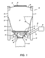
- Fig. 1 illustrates an exemplary embodiment of a dispensing system 10 according to this invention.
- the dispensing system comprises a dispensing container 12 including a chamber 14.
- the chamber contains a powder 16.
- the powder 16 is dispensed from the dispensing container 12 to a receiving container 18 during dispensing operations.
- exemplary embodiments of the dispensing container 12 can include multiple sections.
- the dispensing container 12 includes an upper section 20, a middle section 22 and a lower section 24.
- the upper section 20 includes an upper wall 26.
- the shape of the upper wall 26 can be varied.
- the upper wall 26 can have a square or rectangular shape as depicted in Fig. 2.
- the upper wall 26 can optionally have various other shapes, such as, for example, cylindrical or oval.
- the upper section 20 further includes a top wall 28 having an opening 30 through which the powder 16 is filled into the chamber.
- a removable cover 32 is typically positioned over the opening 30 when the chamber 14 is not being filled with the powder, so as to prevent contamination of the powder 16 in the chamber 14 and/or to prevent any undesired escape of the powder 16 from the chamber 14.
- the middle section 22 of the dispensing container 12 extends below the upper section 20.
- the middle section 22 includes a middle wall 34.
- the middle wall 34 typically has a conical shape, with a diameter that decreases from between the upper section 20 and the lower section 24 of the dispensing container 12.
- the middle wall 34 is oriented to direct the powder 16 toward the center of the chamber 14.
- the middle wall 34 typically is oriented at an angle ⁇ of about 70°. This angle can vary in embodiments of the dispensing system 10.
- the upper section 20 and the middle section 22 of the dispensing container 12 can have a unitary construction.
- the upper section 20 and the middle section 22 can comprise separate sections, attached by any suitable attachment means.
- the lower section 24 of the dispensing container 12 includes a lower wall 36. As shown, the lower wall 36 is inwardly oriented and its diameter decreases in the downward direction toward an outlet 38 of the dispensing container 12.
- the lower wall 36 typically is oriented at an angle ⁇ ranging from about 45° to about 70°, preferably from about 60° to about 70°, and more preferably about 70°.
- the lower section 24 can be separate from the upper section 20 and the middle section 22.
- the lower section 24 and the middle section 22 are attached together using any suitable type of fastener 40. This non-permanent attachment allows the lower section 24 to be removed for cleaning or repair purposes. It also allows lower sections 24 having different sizes, structures and/or configurations to be selectively installed on the dispensing container 12.
- the lower section 24 and the middle section 22 can be of a unitary construction, or can be permanently attached to each other such as by welding, soldering or the like.
- the dispensing container 12 is formed of any suitable material that does not adversely interact with the powder 14. Typically, the dispensing container 12 is formed of a metal such as stainless steel. Other suitable metals, non-metallic materials and combinations of materials, can be used to form the dispensing container 12.
- the dispensing system 10 comprises a fluidizing system that enhances the fluidity of the powder 16 contained in the chamber 14, so as to enhance dispensing of the powder 16.
- the fluidizing system is provided at the lower section 24 of the dispensing container 12.
- the fluidizing system comprises a gas supply 42 and a porous medium 44.
- the porous medium 44 is disposed in the chamber 14 and includes a porous wall having an inner surface 46 and an opposite outer surface 48, as shown in Fig. 3.
- the gas supply 42 supplies a gas into the chamber 14, which flows through the porous medium 44 as depicted by the arrows 50.
- the gas forms a film over the inner surface 46 of the porous medium 44.
- the gas film enhances the movement of the powder 16 over the porous medium 44 and toward the outlet 38 of the dispensing container 12.
- the enhanced fluidity of the powder 16 provides enhanced control of the rate of dispensing of the powder 16 from the dispensing container 12.
- the fluidization system reduces clogging of the powder 16.
- the gas used in the fluidizing system can be any suitable gas. Suitable gases include, but are not limited to, air, oxygen, nitrogen, argon, mixtures thereof, and the like. For example, nitrogen and/or argon may be preferred in embodiments where oxidation of the powder to be dispensed is a concern.
- parameters such as flow rate, gas temperature, and the like can be appropriately controlled to provide desired dispensation from the container.
- the porous medium 44 has a pore structure that preferably at least substantially prevents the powder 16 from passing through the wall from between the inner surface 46 and the outer surface 48. Consequently, the porous medium 44 at least substantially contains the powder 16 to the portion of the chamber 14 that is disposed inward of the inner surface 46 of the porous medium 44. By containing the powder 16 in this manner, leakage of the powder 16 from the dispensing container 12 is reduced.
- porous metallic media such as metallic filters and fluidizing media. These porous metallic media have controlled pore sizes and pore size distributions.
- the porous medium 44 can have a pore structure with a maximum pore size that is smaller than the size of the smallest powder particles contained in the chamber 14.
- the porous medium 44 can also have a selected permeability coefficient to enable the gas to be flowed through the porous medium 44 and into the chamber 14 in a controlled manner. By controlling the gas flow, the fluidity of the powder 16 in the chamber 14 can be controlled. Based on the capabilities of the gas supply 42 of the fluidizing system, the pore structure of the porous medium 44 can be varied to either increase or decrease the flow rate of the gas to respectively increase or decrease the amount of fluidization of the powder 16.
- Porous metal media also have sufficient strength and durability for extended use in the dispensing system 10.
- porous metal media can be formed into thin sheets or plates having a rigid construction and suitable transverse rupture strength.
- the flat, rigid inner surface 46 of the porous medium 44 can enhance the movement of the powder 16 over the inner surface 46.
- the composition of the porous medium 44 can be selected to provide chemical resistance to the powder materials contained in the chamber 14, to prevent undesirable reaction products from being formed and contaminating the powder 16.
- the porous medium 44 can comprise stainless steels, such as sintered stainless steels.
- Suitable exemplary porous metal media that can be used for the porous medium 44 are available from Martin Kurz & Company, Inc. of Long Island, New York
- the porous medium 44 is not limited to metallic materials and can be formed of any other suitable materials that provide the desired characteristics including pore structure, mechanical properties and chemical resistance.
- the porous medium 44 can be formed of suitable ceramic materials or combinations of metals and ceramic materials that have these characteristics.
- the gas supply 42 of the fluidizing system comprises one or more inlets 52 that include gas flow passages 54 through which the gas is flowed into the chamber 14 from a gas source 56.
- the inlets 52 can comprise conduits.
- the gas source 56 can be any suitable pump, for example.
- the gas source 56 can provide a selected gas flow rate of from about 0.1 bar to about 7 bar into the chamber 14.
- the gas flow rate can be selectively varied to control the level of fluidization of the powder 16 in the chamber 14.
- the porous medium 44 can filter the gas flowed into the chamber 14 by the gas source 56 to prevent any undesirable substances from being introduced into the chamber 14.
- the dispensing system 10 also includes a valve 60.
- the valve 60 is operable to dispense the powder 16 from the dispensing container 12 to the receiving vessel 18.
- the valve 60 enables the powder 16 to be dispensed from the dispensing container 12 in a controlled manner and with at least substantial containment of the powder 16 within the dispensing system 10.
- the valve 60 comprises a first portion 62 and a second portion 64.
- the first portion 62 is attached to the bottom end of the lower section 24 of the dispensing container 12.
- the second portion 64 is attachable to the receiving container 18 to which the powder 16 is transferred from the dispensing container 12.
- An exemplary suitable type of valve for use in the dispensing system 10 is a split discharge valve. Such valves are available from Serck Audco Valves of Houston, Texas.
- the valve 60 can include a lock 66 that secures the first portion 62 to the second portion 64 in a locked condition, and allows the first portion 62 and second portion 64 to be separated from each other in an unlocked condition.
- the valve 60 is locked when the powder 16 is dispensed from the dispensing container 12 to the receiving container 18.
- the valve 60 is then unlocked after powder 16 has been dispensed.
- the lock 66 can comprise any suitable locking mechanism for this purpose.
- the first portion 62 and the second portion 64 can be quickly and easily coupled together for dispensing purposes and then separated after dispensing has been completed.
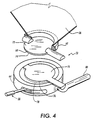
- the first portion 62 of the valve 60 includes a first disk 68 and the second portion 64 includes a second disk 70.
- the first disk 68 includes a top face 72 and a bottom face 74.
- the second disk 70 includes a top face 76 and a bottom face 78.
- the first disk 68 rotates between at least one closed position and at least one open position. Typically, the first disk 68 rotates over a range of about 90°, representing a range of open positions. In the closed position, the first disk 68 closes the outlet 38 of the dispensing container 12 and prevents the powder 16 from being dispensed from the dispensing container 12. In the open position(s), the powder 16 can be dispensed from the dispensing container 12 through the valve 60. By varying the open position of the first disk 68, the dispensing rate of the powder 16 from the dispensing container 12 can be selectively varied.
- the bottom face 74 of the first disk 68 is configured to mate with the top face 76 of the second disk 70 in a face-to-face relationship when the first portion 62 is secured to the second portion 64 in the locked condition of the valve 60.
- the first disk 68 and the second disk 70 both move together between the closed position and the open position(s) of the valve 60.
- the valve 60 can include a handle 80 that is operatively associated with the first disk 68 and/or the second disk 70.
- the handle 80 is provided on the second portion 64 of the valve 60 in the illustrated embodiment. The handle 80 is turned to rotate the first disk 68 and the second disk 70 to selectively open and close the valve 60.
- valve 60 can be automatically controlled to open and close the valve 60 by pneumatic or electrical actuation.
- the bottom face 74 of the first disk 68 is covered by the top face 76 of the second disk 70. Consequently, the bottom face 74 does not contact the powder 16 in either the closed position(s) or the open position(s) of the valve 60. Rather, only the top face 72 of the first disk 68 contacts the powder 16.
- the powder 16 is thus contained within the chamber 14 when the valve 60 is closed, and there is no powder 16 on the bottom face 74 that can drop onto the floor or become entrained in the surrounding air.
- This containment of the powder 16 reduces waste of the powder 16 and also reduces the level of dust exposure of the powder 16 in the surrounding environment.
- the dispensing system 10 can reduce safety and health concerns and reduce shopkeeping problems associated with the presence of the powder 16 in the surrounding environment.
- the container 10 comprises supports 82 for supporting the dispensing system 10 on a surface.
- the dispensing system 10 can include rollers or the like on the dispensing container 12 to enable the dispensing container 12 to be pushed or rolled over a surface to different locations in a facility without having to be lifted.
- Exemplary embodiments of the dispensing system 10 according to this invention can be sized to contain and dispense various amounts of powders, depending on the intended uses of the dispensing system 10.
- the dispensing container 12 has a height of from about 4 feet to about 6 feet.
- the chamber 14 of the dispensing container 12 is typically sized to contain from about 500 pounds to about 1000 pounds.
- the dimensions of the dispensing container 12 are exemplary only, and are dependent upon a number of factors including the particular powder to be dispensed, density and other properties of the powder, space concerns, powder availability, and the like. Also, the dimensions of the dispensing container 12 can be varied depending on the type and size of receiving container 18 to which the powder is being dispensed. Based on these and other considerations, dispensing containers 12 of other dimensions can be readily prepared and used based on the present specification.
- Exemplary embodiments of the dispensing system 10 according to this invention can dispense powders typically at a rate of from about 1000 lb/hr to about 20,000 lb/hr.
- powder dispensing rates are exemplary only, and are dependent upon a number of factors including size of the containers, size of the valve opening, density and other properties of the powder, and the like. Dispensing rates outside these ranges can be used, in embodiments.
- the dispensing system 10 is particularly suitable for dispensing toner.
- the toner can be either magnetic or non-magnetic toners, as desired.
- the toner also can be either a homogeneous product, or can be a mixture of component products.
- the toner can be pre-blended, extruded, ground, classified, blended or screened.
- dispensing system can also be used to dispense developers and mixtures of toner and developers.
- the dispensing system 10 when used to contain and dispense toner, the dispensing system 10 can contain the dust level of the toner in the surrounding environment to less than about 10 ⁇ g/m 3 .
- This dust level is significantly below the current dust exposure guidelines and requirements in various industries, which are typically as high as about 400 ⁇ g/m 3 .
- the dispensing system 10 can exceed the required performance levels in various applications.
- the dispensing container 12 can be a toner hopper.
- the receiving container 18 can comprise any suitable container for receiving the toner.
- the receiving container can be rigid or flexible.
- the receiving container can be various bags, rotary valves, feeders, hoppers and bins. It will be understood by those skilled in the art that other types of receiving containers 18 can also be used to receive the powder dispensed from the dispensing container 12.
Landscapes
- Engineering & Computer Science (AREA)
- Mechanical Engineering (AREA)
- Basic Packing Technique (AREA)
- Filling Or Emptying Of Bunkers, Hoppers, And Tanks (AREA)
- Electrostatic Spraying Apparatus (AREA)
Applications Claiming Priority (2)
| Application Number | Priority Date | Filing Date | Title |
|---|---|---|---|
| US09/587,391 US6311745B1 (en) | 2000-06-05 | 2000-06-05 | Systems and methods for dispensing powders |
| US587391 | 2000-06-05 |
Publications (3)
| Publication Number | Publication Date |
|---|---|
| EP1162140A2 true EP1162140A2 (de) | 2001-12-12 |
| EP1162140A3 EP1162140A3 (de) | 2002-04-10 |
| EP1162140B1 EP1162140B1 (de) | 2004-01-28 |
Family
ID=24349603
Family Applications (1)
| Application Number | Title | Priority Date | Filing Date |
|---|---|---|---|
| EP20010113426 Expired - Lifetime EP1162140B1 (de) | 2000-06-05 | 2001-06-01 | Vorrichtung und Verfahren zum Abgeben von Pulvern |
Country Status (5)
| Country | Link |
|---|---|
| US (1) | US6311745B1 (de) |
| EP (1) | EP1162140B1 (de) |
| BR (1) | BR0102264A (de) |
| CA (1) | CA2344138C (de) |
| DE (1) | DE60101866T2 (de) |
Cited By (3)
| Publication number | Priority date | Publication date | Assignee | Title |
|---|---|---|---|---|
| CN102730206A (zh) * | 2012-07-14 | 2012-10-17 | 长沙通发高新技术开发有限公司 | 可用于采制样产品打包机上的样料进口机构 |
| US9266688B2 (en) | 2010-09-30 | 2016-02-23 | General Electric Company | Feed vessels and systems for pneumatically conveying solid particles |
| CN111148620A (zh) * | 2017-10-18 | 2020-05-12 | 惠普发展公司,有限责任合伙企业 | 用于3d打印系统的构建材料料斗 |
Families Citing this family (29)
| Publication number | Priority date | Publication date | Assignee | Title |
|---|---|---|---|---|
| GB0004845D0 (en) * | 2000-02-29 | 2000-04-19 | Tetronics Ltd | A method and apparatus for packaging ultra fine powders into containers |
| GB2364875A (en) * | 2000-07-10 | 2002-02-06 | Tetronics Ltd | A plasma torch electrode |
| DE20014872U1 (de) * | 2000-08-28 | 2001-01-25 | GEA Powder Technology GmbH, 79379 Müllheim | Vorrichtung zum Kuppeln zweier Aufbewahrungs- und/oder Fördermittel mit einer Reinigungseinrichtung |
| TWI220896B (en) * | 2002-01-30 | 2004-09-11 | Ricoh Kk | Apparatus and method of filling microscopic powder |
| JP4220798B2 (ja) * | 2002-09-20 | 2009-02-04 | 株式会社リコー | 粉体収納容器 |
| CN1791533B (zh) * | 2003-03-20 | 2012-07-11 | 株式会社理光 | 粉体充填装置和方法、及回转状辅助容器 |
| US7156372B2 (en) * | 2003-12-19 | 2007-01-02 | Eastman Kodak Company | Non-contact valve for particulate material |
| EP1584990A1 (de) * | 2004-04-05 | 2005-10-12 | Ricoh Co., Ltd. | Tonerzufuhrvorrichtung mit Gas-Zuführung |
| US7402753B2 (en) * | 2005-01-12 | 2008-07-22 | Schlumberger Technology Corporation | Enhanced electrical cables |
| PL1698553T3 (pl) * | 2005-03-04 | 2009-12-31 | Indag Gesellschaft Fuer Ind Mbh & Co Betriebs Kg | Urządzenie i sposób do napełniania woreczków foliowych produktami spożywczymi |
| US7540308B2 (en) * | 2005-06-07 | 2009-06-02 | Schlumberger Technology Corporation | Method of supplying a powdered chemical composition to a wellsite |
| EP1932789A1 (de) * | 2006-12-15 | 2008-06-18 | GEA Niro GmbH | Kupplungsverschluss sowie Andockeinrichtung, enthaltend zwei dieser Kupplungsverschlüsse |
| US9073025B2 (en) * | 2007-09-11 | 2015-07-07 | Res Usa, Llc | System and method for catalyst loading/mixing |
| FR2927062B1 (fr) * | 2008-02-04 | 2011-07-01 | Arkema France | Procede de remplissage securise de nanotubes de carbone, systeme de remplissage et installation industrielle mettant en oeuvre le procede. |
| DE102011114573B4 (de) | 2011-09-30 | 2014-02-27 | Sartorius Stedim Biotech Gmbh | Ventilvorrichtung und Verfahren zumTransferieren eines Transfermediums |
| KR20150091069A (ko) * | 2012-12-04 | 2015-08-07 | 네스텍 소시에테아노님 | 분말을 운송하고 가압하기 위한 장치 및 방법 |
| AU2014237422B2 (en) * | 2013-03-15 | 2018-02-22 | Designed by M.E., LLC | Method and apparatus for making a filled sachet |
| GB2520191B (en) * | 2014-09-24 | 2015-10-07 | Lpw Technology Ltd | A powder container comprising a pressure vessel and a pilot line |
| CN105752710A (zh) * | 2016-04-28 | 2016-07-13 | 江苏紫石机械制造有限公司 | 除尘漏斗 |
| US10562062B2 (en) | 2016-11-21 | 2020-02-18 | Ecolab Usa Inc. | Material supply system with valve assembly |
| EP4253273A3 (de) | 2016-11-21 | 2024-03-27 | Ecolab USA Inc. | Materialversorgungssystem mit ventilanordnung mit verbesserten dichtfähigkeiten |
| WO2019112948A1 (en) | 2017-12-04 | 2019-06-13 | Ecolab Usa Inc. | Material wetting system with shroud assembly |
| EP3720795B1 (de) | 2017-12-04 | 2025-01-29 | Ecolab USA Inc. | Trichtersystem für pulvermaterial mit versetzter beladung |
| FR3074484B1 (fr) * | 2017-12-05 | 2021-04-30 | Addup | Container inertable de transport d'une poudre de fabrication additive |
| US20190321888A1 (en) * | 2018-04-18 | 2019-10-24 | Tytus3D System Inc. | Apparatus for dispensing content |
| US11027959B2 (en) * | 2018-06-29 | 2021-06-08 | Matsys Inc. | Fluidized powder valve system |
| US11614698B2 (en) | 2018-08-30 | 2023-03-28 | Hewlett-Packard Development Company, L.P. | Sealed print particle transfer interface |
| DE102019006199B3 (de) * | 2019-09-03 | 2021-02-11 | BLOCKHELDEN GmbH | Ausgabevorrichtung zur handbedienten, dosierten Ausgabe von pulverförmigem, hygroskopischem Material |
| GB2602781B (en) * | 2020-10-13 | 2026-04-08 | Chargepoint Tech Limited | Improvements relating to valves |
Citations (2)
| Publication number | Priority date | Publication date | Assignee | Title |
|---|---|---|---|---|
| US4974646A (en) | 1987-11-23 | 1990-12-04 | Portals Engineering Limited | Powder flow control valve |
| US5727607A (en) | 1995-01-26 | 1998-03-17 | Ricoh Company, Ltd. | Powder feeding method and apparatus for feeding powders with a fluid with increased precision |
Family Cites Families (6)
| Publication number | Priority date | Publication date | Assignee | Title |
|---|---|---|---|---|
| US4212331A (en) * | 1978-12-01 | 1980-07-15 | Victor Benatar | Pressurized apparatus for discharging powdered reagent from a shipping container |
| US5295507A (en) * | 1992-01-29 | 1994-03-22 | Eli Lilly And Company | Containment valve that allows contamination free transfer |
| US5150735A (en) * | 1992-01-29 | 1992-09-29 | Eli Lilly And Company | Containment valve that allows contamination free transfer |
| DE4342962C1 (de) * | 1993-12-16 | 1995-02-02 | Buck Chem Tech Werke | Vorrichtung zum Kuppeln von Behältnissen |
| EP0788989A3 (de) * | 1995-09-20 | 1998-07-01 | Buck Werke GmbH & Co | Vorrichtung zum Kuppeln von Behältnissen |
| DE19641827C2 (de) * | 1996-10-10 | 2002-11-21 | Gea Buck Valve Gmbh | Austraghilfe für schwerfließende Schüttgüter aus Behältern |
-
2000
- 2000-06-05 US US09/587,391 patent/US6311745B1/en not_active Expired - Lifetime
-
2001
- 2001-04-17 CA CA 2344138 patent/CA2344138C/en not_active Expired - Fee Related
- 2001-06-01 DE DE2001601866 patent/DE60101866T2/de not_active Expired - Lifetime
- 2001-06-01 EP EP20010113426 patent/EP1162140B1/de not_active Expired - Lifetime
- 2001-06-04 BR BR0102264A patent/BR0102264A/pt not_active Application Discontinuation
Patent Citations (2)
| Publication number | Priority date | Publication date | Assignee | Title |
|---|---|---|---|---|
| US4974646A (en) | 1987-11-23 | 1990-12-04 | Portals Engineering Limited | Powder flow control valve |
| US5727607A (en) | 1995-01-26 | 1998-03-17 | Ricoh Company, Ltd. | Powder feeding method and apparatus for feeding powders with a fluid with increased precision |
Cited By (5)
| Publication number | Priority date | Publication date | Assignee | Title |
|---|---|---|---|---|
| US9266688B2 (en) | 2010-09-30 | 2016-02-23 | General Electric Company | Feed vessels and systems for pneumatically conveying solid particles |
| CN102730206A (zh) * | 2012-07-14 | 2012-10-17 | 长沙通发高新技术开发有限公司 | 可用于采制样产品打包机上的样料进口机构 |
| CN111148620A (zh) * | 2017-10-18 | 2020-05-12 | 惠普发展公司,有限责任合伙企业 | 用于3d打印系统的构建材料料斗 |
| EP3642015A4 (de) * | 2017-10-18 | 2021-03-10 | Hewlett-Packard Development Company, L.P. | Baumaterialbehälter für 3d-druck-systeme |
| CN111148620B (zh) * | 2017-10-18 | 2022-03-11 | 惠普发展公司,有限责任合伙企业 | 用于3d打印系统的构建材料料斗 |
Also Published As
| Publication number | Publication date |
|---|---|
| DE60101866D1 (de) | 2004-03-04 |
| BR0102264A (pt) | 2002-02-19 |
| CA2344138A1 (en) | 2001-12-05 |
| US6311745B1 (en) | 2001-11-06 |
| EP1162140A3 (de) | 2002-04-10 |
| EP1162140B1 (de) | 2004-01-28 |
| CA2344138C (en) | 2005-06-14 |
| DE60101866T2 (de) | 2004-07-15 |
Similar Documents
| Publication | Publication Date | Title |
|---|---|---|
| US6311745B1 (en) | Systems and methods for dispensing powders | |
| US6354465B2 (en) | Protable device for accurately metering and delivering cohesive bulk solid powders | |
| JP4017979B2 (ja) | 大型バルクコンテナからバルク粉末を取り出すためのシステムおよび方法 | |
| US6325572B1 (en) | Process and device for pneumatically conveying powdery substances and their use | |
| US5096096A (en) | Fluidized bed discharge bin | |
| EP1254835A2 (de) | Verfahren und Vorrichtung zum Verpacken von Pulver | |
| US6227768B1 (en) | Particulate conveyor device and apparatus | |
| US6021821A (en) | Particulate processing apparatus | |
| JP2000118501A (ja) | 粉体処理装置 | |
| US5988234A (en) | Apparatus for particulate processing | |
| JP2001139152A (ja) | 粒子システムのための機械的なバルブを備えた高速エアノズル | |
| US20070201904A1 (en) | Particle supply apparatus, imaging apparatus, and monitoring system | |
| EP2000861B1 (de) | Teilchenausgabevorrichtung, Bilderzeugungsvorrichtung und Transportverfahren für eine Teilchenanpassungseinheit | |
| JP2000335519A (ja) | 粒子材料供給装置 | |
| AU2002231346A1 (en) | A system and method for unloading bulk powder from large bulk containers | |
| EP0380255B1 (de) | System zur Beförderung von Materialien | |
| CS217993B2 (en) | Storing container for hard particled material | |
| CS216824B2 (en) | Facility for dosing the fine grained material | |
| WO2021099805A1 (en) | Material discharge apparatus and related methods | |
| US6871758B2 (en) | Precision adaptive powder dispenser | |
| US7302975B2 (en) | Method and system for increasing density of toner in a toner container | |
| JP5181387B2 (ja) | 粉粒体供給用カプラ、およびそれを用いた粉粒体供給機構、並びにその機構を含む粉粒体供給システム | |
| US11027959B2 (en) | Fluidized powder valve system | |
| AU723077B2 (en) | Non-magnetic toner dynamic recycling | |
| JPH0158026B2 (de) |
Legal Events
| Date | Code | Title | Description |
|---|---|---|---|
| PUAI | Public reference made under article 153(3) epc to a published international application that has entered the european phase |
Free format text: ORIGINAL CODE: 0009012 |
|
| AK | Designated contracting states |
Kind code of ref document: A2 Designated state(s): AT BE CH CY DE DK ES FI FR GB GR IE IT LI LU MC NL PT SE TR Kind code of ref document: A2 Designated state(s): DE FR GB |
|
| AX | Request for extension of the european patent |
Free format text: AL;LT;LV;MK;RO;SI |
|
| PUAL | Search report despatched |
Free format text: ORIGINAL CODE: 0009013 |
|
| AK | Designated contracting states |
Kind code of ref document: A3 Designated state(s): AT BE CH CY DE DK ES FI FR GB GR IE IT LI LU MC NL PT SE TR |
|
| AX | Request for extension of the european patent |
Free format text: AL;LT;LV;MK;RO;SI |
|
| RIC1 | Information provided on ipc code assigned before grant |
Free format text: 7B 65B 1/16 A, 7B 65B 1/28 B, 7B 65G 69/18 B |
|
| 17P | Request for examination filed |
Effective date: 20021010 |
|
| AKX | Designation fees paid |
Free format text: DE FR GB |
|
| 17Q | First examination report despatched |
Effective date: 20030114 |
|
| GRAP | Despatch of communication of intention to grant a patent |
Free format text: ORIGINAL CODE: EPIDOSNIGR1 |
|
| GRAS | Grant fee paid |
Free format text: ORIGINAL CODE: EPIDOSNIGR3 |
|
| GRAA | (expected) grant |
Free format text: ORIGINAL CODE: 0009210 |
|
| AK | Designated contracting states |
Kind code of ref document: B1 Designated state(s): DE FR GB |
|
| REG | Reference to a national code |
Ref country code: GB Ref legal event code: FG4D |
|
| REG | Reference to a national code |
Ref country code: IE Ref legal event code: FG4D |
|
| REF | Corresponds to: |
Ref document number: 60101866 Country of ref document: DE Date of ref document: 20040304 Kind code of ref document: P |
|
| ET | Fr: translation filed | ||
| PLBE | No opposition filed within time limit |
Free format text: ORIGINAL CODE: 0009261 |
|
| STAA | Information on the status of an ep patent application or granted ep patent |
Free format text: STATUS: NO OPPOSITION FILED WITHIN TIME LIMIT |
|
| 26N | No opposition filed |
Effective date: 20041029 |
|
| REG | Reference to a national code |
Ref country code: IE Ref legal event code: MM4A |
|
| REG | Reference to a national code |
Ref country code: GB Ref legal event code: 746 Effective date: 20050404 |
|
| REG | Reference to a national code |
Ref country code: FR Ref legal event code: PLFP Year of fee payment: 16 |
|
| PGFP | Annual fee paid to national office [announced via postgrant information from national office to epo] |
Ref country code: GB Payment date: 20160527 Year of fee payment: 16 Ref country code: DE Payment date: 20160524 Year of fee payment: 16 |
|
| PGFP | Annual fee paid to national office [announced via postgrant information from national office to epo] |
Ref country code: FR Payment date: 20160526 Year of fee payment: 16 |
|
| REG | Reference to a national code |
Ref country code: DE Ref legal event code: R119 Ref document number: 60101866 Country of ref document: DE |
|
| GBPC | Gb: european patent ceased through non-payment of renewal fee |
Effective date: 20170601 |
|
| REG | Reference to a national code |
Ref country code: FR Ref legal event code: ST Effective date: 20180228 |
|
| PG25 | Lapsed in a contracting state [announced via postgrant information from national office to epo] |
Ref country code: GB Free format text: LAPSE BECAUSE OF NON-PAYMENT OF DUE FEES Effective date: 20170601 Ref country code: DE Free format text: LAPSE BECAUSE OF NON-PAYMENT OF DUE FEES Effective date: 20180103 |
|
| PG25 | Lapsed in a contracting state [announced via postgrant information from national office to epo] |
Ref country code: FR Free format text: LAPSE BECAUSE OF NON-PAYMENT OF DUE FEES Effective date: 20170630 |