EP1162382A2 - Compresseur à gaz et système de conditionnement d'air - Google Patents
Compresseur à gaz et système de conditionnement d'air Download PDFInfo
- Publication number
- EP1162382A2 EP1162382A2 EP01304918A EP01304918A EP1162382A2 EP 1162382 A2 EP1162382 A2 EP 1162382A2 EP 01304918 A EP01304918 A EP 01304918A EP 01304918 A EP01304918 A EP 01304918A EP 1162382 A2 EP1162382 A2 EP 1162382A2
- Authority
- EP
- European Patent Office
- Prior art keywords
- electro
- magnetic clutch
- temperature
- temperature sensor
- gas compressor
- Prior art date
- Legal status (The legal status is an assumption and is not a legal conclusion. Google has not performed a legal analysis and makes no representation as to the accuracy of the status listed.)
- Granted
Links
Images




Classifications
-
- F—MECHANICAL ENGINEERING; LIGHTING; HEATING; WEAPONS; BLASTING
- F16—ENGINEERING ELEMENTS AND UNITS; GENERAL MEASURES FOR PRODUCING AND MAINTAINING EFFECTIVE FUNCTIONING OF MACHINES OR INSTALLATIONS; THERMAL INSULATION IN GENERAL
- F16D—COUPLINGS FOR TRANSMITTING ROTATION; CLUTCHES; BRAKES
- F16D27/00—Magnetically- or electrically- actuated clutches; Control or electric circuits therefor
- F16D27/02—Magnetically- or electrically- actuated clutches; Control or electric circuits therefor with electromagnets incorporated in the clutch, i.e. with collecting rings
- F16D27/04—Magnetically- or electrically- actuated clutches; Control or electric circuits therefor with electromagnets incorporated in the clutch, i.e. with collecting rings with axially-movable friction surfaces
- F16D27/06—Magnetically- or electrically- actuated clutches; Control or electric circuits therefor with electromagnets incorporated in the clutch, i.e. with collecting rings with axially-movable friction surfaces with friction surfaces arranged within the flux
-
- F—MECHANICAL ENGINEERING; LIGHTING; HEATING; WEAPONS; BLASTING
- F16—ENGINEERING ELEMENTS AND UNITS; GENERAL MEASURES FOR PRODUCING AND MAINTAINING EFFECTIVE FUNCTIONING OF MACHINES OR INSTALLATIONS; THERMAL INSULATION IN GENERAL
- F16D—COUPLINGS FOR TRANSMITTING ROTATION; CLUTCHES; BRAKES
- F16D48/00—External control of clutches
- F16D48/06—Control by electric or electronic means, e.g. of fluid pressure
- F16D48/064—Control of electrically or electromagnetically actuated clutches
-
- F—MECHANICAL ENGINEERING; LIGHTING; HEATING; WEAPONS; BLASTING
- F16—ENGINEERING ELEMENTS AND UNITS; GENERAL MEASURES FOR PRODUCING AND MAINTAINING EFFECTIVE FUNCTIONING OF MACHINES OR INSTALLATIONS; THERMAL INSULATION IN GENERAL
- F16D—COUPLINGS FOR TRANSMITTING ROTATION; CLUTCHES; BRAKES
- F16D2500/00—External control of clutches by electric or electronic means
- F16D2500/10—System to be controlled
- F16D2500/104—Clutch
- F16D2500/10443—Clutch type
- F16D2500/10475—Magnetic field, e.g. electro-rheological, magnetisable particles
-
- F—MECHANICAL ENGINEERING; LIGHTING; HEATING; WEAPONS; BLASTING
- F16—ENGINEERING ELEMENTS AND UNITS; GENERAL MEASURES FOR PRODUCING AND MAINTAINING EFFECTIVE FUNCTIONING OF MACHINES OR INSTALLATIONS; THERMAL INSULATION IN GENERAL
- F16D—COUPLINGS FOR TRANSMITTING ROTATION; CLUTCHES; BRAKES
- F16D2500/00—External control of clutches by electric or electronic means
- F16D2500/30—Signal inputs
- F16D2500/304—Signal inputs from the clutch
- F16D2500/30404—Clutch temperature
-
- F—MECHANICAL ENGINEERING; LIGHTING; HEATING; WEAPONS; BLASTING
- F16—ENGINEERING ELEMENTS AND UNITS; GENERAL MEASURES FOR PRODUCING AND MAINTAINING EFFECTIVE FUNCTIONING OF MACHINES OR INSTALLATIONS; THERMAL INSULATION IN GENERAL
- F16D—COUPLINGS FOR TRANSMITTING ROTATION; CLUTCHES; BRAKES
- F16D2500/00—External control of clutches by electric or electronic means
- F16D2500/50—Problem to be solved by the control system
- F16D2500/504—Relating the engine
- F16D2500/5041—Control of engine accessories, e.g. air conditioning, pumps, auxiliary drive
-
- F—MECHANICAL ENGINEERING; LIGHTING; HEATING; WEAPONS; BLASTING
- F16—ENGINEERING ELEMENTS AND UNITS; GENERAL MEASURES FOR PRODUCING AND MAINTAINING EFFECTIVE FUNCTIONING OF MACHINES OR INSTALLATIONS; THERMAL INSULATION IN GENERAL
- F16D—COUPLINGS FOR TRANSMITTING ROTATION; CLUTCHES; BRAKES
- F16D2500/00—External control of clutches by electric or electronic means
- F16D2500/50—Problem to be solved by the control system
- F16D2500/51—Relating safety
- F16D2500/5104—Preventing failures
- F16D2500/5106—Overheat protection
-
- F—MECHANICAL ENGINEERING; LIGHTING; HEATING; WEAPONS; BLASTING
- F16—ENGINEERING ELEMENTS AND UNITS; GENERAL MEASURES FOR PRODUCING AND MAINTAINING EFFECTIVE FUNCTIONING OF MACHINES OR INSTALLATIONS; THERMAL INSULATION IN GENERAL
- F16D—COUPLINGS FOR TRANSMITTING ROTATION; CLUTCHES; BRAKES
- F16D2500/00—External control of clutches by electric or electronic means
- F16D2500/50—Problem to be solved by the control system
- F16D2500/51—Relating safety
- F16D2500/5108—Failure diagnosis
-
- F—MECHANICAL ENGINEERING; LIGHTING; HEATING; WEAPONS; BLASTING
- F16—ENGINEERING ELEMENTS AND UNITS; GENERAL MEASURES FOR PRODUCING AND MAINTAINING EFFECTIVE FUNCTIONING OF MACHINES OR INSTALLATIONS; THERMAL INSULATION IN GENERAL
- F16D—COUPLINGS FOR TRANSMITTING ROTATION; CLUTCHES; BRAKES
- F16D2500/00—External control of clutches by electric or electronic means
- F16D2500/70—Details about the implementation of the control system
- F16D2500/704—Output parameters from the control unit; Target parameters to be controlled
- F16D2500/70402—Actuator parameters
- F16D2500/7041—Position
Definitions
- This invention relates to a gas compressor which receives compressive power from outside through an electro-magnetic clutch and to an air conditioning system having this gas compressor.
- vane-rotary-type gas compressors many of the vane-rotary-type gas compressors, scroll-type gas compressors, swash-plate-type gas compressors, etc. used in automotive air conditioners, GHP or the like, receive drive power from outside through an electro-magnetic clutch.
- An electro-magnetic clutch 10 is mounted to a case cover 23 provided in the outer periphery of one end portion of a rotor shaft 22 retaining a rotor 21 equipped with vanes 20.
- stationary portions of the electro-magnetic clutch 10 which do not rotate that is, an annular core 11 and a coil 12 provided inside the core 11, are mounted to an intermediate shoulder end surface 23a of the case cover 23 by means of a retaining ring 13a through the intermediation of a core flange portion 13 of the core 11.
- the core flange portion 13 has a protrusion 13b, which is fitted into a recess 23b of the intermediate shoulder end surface 23a of the above-mentioned case cover to thereby prevent rotation of the core 11.
- an armature friction plate 14 a buckling 15, an elastic coupling body 16, a base plate 17, and a hub 18 are connected together.
- the hub 18 is further connected to the rotor shaft 22.
- the armature friction plate 14 and the buckling 15 are connected to each other by means of a plurality of joint pins 15a.
- the buckling 15 and the base plate 17 are integrally connected to each other by the elastic coupling body 16, which is formed of torsional rubber.
- the elastic coupling body 16 undergoes elastic deformation.
- the base plate 17 and the hub 18 are connected to each other by means of a plurality of joint pins 17a.
- the hub 18 is fastened to one end of the rotor shaft 22 by means of a spline 24 so as to be connected to a compressor main body 25 side.
- the rotatable driving portion of the electro-magnetic clutch comprises a pulley 26 formed of a magnetic material, and this pulley 26 is mounted to the case cover 23 through the intermediation of a ball bearing 27.
- an inner peripheral portion 26a forming a bearing housing and an outer peripheral portion 26c having pulley grooves 26b in the outer periphery thereof are connected to each other on a pulley end surface 26d side so as to define a U-shaped sectional configuration, and the core 11 is accommodated in the recess thus defined.
- Numeral 19 indicates holes for forming a magnetic circuit between the armature friction plate 14 and the pulley 26.
- the pulley 26 on the driving side is rotated by a belt (not shown) entrained about it and about the output shaft of the engine.
- the electro-magnetic clutch 10 is not energized, the armature friction plate 14 on the driven side is spaced apart from the pulley 26, and does not rotate. In this state, the gas compressor is at rest.
- the ball bearing 27 When the ball bearing 27 generates more heat than usual due to poor lubrication, wear, etc. and attains a high temperature as shown in Fig. 7, the heat is transmitted to the core 11 of the electro-magnetic clutch 10, which is beside the ball bearing surface and which surrounds the outer periphery of the bearing, and the core 11 also attains a high temperature, with the result that the mold thereof is melted, which may cause short-circuiting of the wiring. Further, the coil 12 and the portion of the pulley 26 near the end friction surface 26d also attain a high temperature, resulting in a reduction in the magnetomotive force of the electro-magnetic clutch 10, as shown in Fig. 8.
- the reduction in the magnetomotive force weakens the attracting force acting between the pulley 26 and the armature friction plate 14, and slippage occurs therebetween, thereby generating sparks. Further, the frictional heat generated causes an increase in the ambient temperature, thereby destroying the elastic coupling body 16 made of rubber. In this state, the armature friction plate 14 comes into contact with the hub 18, and frictional heat is generated to thereby generate sparks, with the result that the core 11 undergoes further temperature rise. Further, the rotor shaft 22 ceases to rotate in the normal manner.
- the mold When the temperature of the core 11 exceeds 200°C, the mold is softened and melted. If such an acute temperature rise can be detected before this temperature level is reached, this trouble could be prevented.
- clutch slippage i.e., slippage between the pulley end surface 26d and the armature friction plate 14 occurs.
- this slippage mitigates the shock at the time of start-up, allowing the system to start smoothly.
- Repetition of start-up operation leads to gradual wear of the contact surface of the armature friction plate 14.
- minute slippage occurs as a result of fluctuations in load in rotor rotation, momentary overload, etc.
- Clutch slippage naturally involves heat generation.
- An abnormal increase in the slippage between the pulley end surface 26d and the armature friction plate 14 as a result of wear of the armature friction plate 14, etc. causes an increase in slippage and heat generation, which can damage the contact surfaces and fuse them together. Damage to the contact surfaces will cause a further increase in clutch slippage or make them incapable of coming into contact with each other, which means the engagement of the clutch cannot be effected. Fusion of the contact surfaces makes it impossible to effect disengagement of the clutch.
- anomalous clutch slippage is accompanied by radiation of heat and generation of sparks due to anomalous heat generation, which means the above trouble could be prevented if these phenomena can be detected.
- This invention has been made in order to solve the above problem in the prior art. It is accordingly an object of this invention to provide a gas compressor and an air conditioning system in which it is possible to detect an abnormal temperature rise in the electro-magnetic clutch at an early stage to stop the energization thereof or stop the operation of the air conditioning system as a whole.
- the temperature sensor is preferably arranged in the vicinity of the armature friction plate or mounted to the core flange portion for mounting the electro-magnetic clutch or to a portion in the vicinity of the core or the ball bearing of the electro-magnetic clutch so as to be externally detachable.
- an air conditioning system of the type which includes a gas compressor in which external drive power is transmitted to the compressor main body through an electro-magnetic clutch, the air conditioning system comprising a temperature sensor mounted to the electro-magnetic clutch or to a portion in the vicinity thereof, an outlying temperature decision means for making a judgment as to whether the detection output of the temperature sensor is an anomalous value, and an emergency stop means which interrupts a driving circuit of the electro-magnetic clutch or stops the air conditioning system upon receiving an anomaly decision output from the outlying temperature decision means.
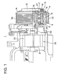
- Fig. 1 is a longitudinal sectional view of a gas compressor according to an embodiment of this invention
- Fig. 2 is an enlarged partial view of Fig. 1
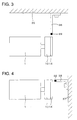
- Figs. 3 and 4 are explanatory diagrams showing other embodiments of this invention
- Fig. 5 is a block diagram showing a control system for coping with anomalous temperature in the air conditioning system of this invention having a gas compressor as shown in Figs. 1, 3, 4, etc.
- the gas compressor 1 is of the type which is operated by transmitting external power to the compressor main body 25 through the electro-magnetic clutch 10. Further, the relationship between the air conditioning system 2 of Fig. 5 and the gas compressor 1 is well known in the art, so a detailed description thereof will be omitted here.
- a screw hole 30 is provided in the core flange portion 13 fastened to the core 11, at a position near the core 11 of the electro-magnetic clutch 10, and a temperature sensor (which is a thermistor sensor in this embodiment) 29 is fastened to the core flange portion 13 so as to be externally detachable by passing a screw 31 through the temperature sensor 29 and engaging screw with the screw hole 30.
- a temperature sensor which is a thermistor sensor in this embodiment
- the temperature sensor 29 it is desirable for the temperature sensor 29 to be mounted at a position where it can be easily replaced whenever it is out of order. Apart from the position in the core flange portion 13 near the core 11, the temperature sensor 29 may be mounted to the case cover 23 which is nearby so that it can be easily attached and detached. It is also possible to mount the temperature sensor 29 directly to the core 11 so as to detect a temperature nearer to that of the core. Further, since, in many cases, anomalous temperature rise in the electro-magnetic clutch 10 is attributable to anomalous heat generation in the ball bearing (which is a ball bearing in this embodiment) 27, it is desirable to arrange the temperature sensor 29 near the ball bearing 27.
- the present invention is applied to an automotive air conditioner, in which anomalous heat generation due to clutch slippage is detected at an early stage by detecting the radiant heat from the armature friction plate.
- numeral 35 indicates an engine body, to which a stay 36 having the temperature sensor 29 at its forward end is mounted.
- the temperature sensor 29 is situated in the vicinity of the outer periphery of the armature friction plate 14 of the electro-magnetic clutch 10.
- Numeral 1 indicates a gas compressor.
- the temperature sensor 29 of Fig. 3 senses radiation heat generated as a result of slippage between the armature friction plate 14 and the pulley end surface 26d (See Fig. 2), thus checking the armature friction plate 14 for anomalous heat generation.
- Fig. 4 shows still another embodiment of this invention.
- the present invention is applied to an automotive air conditioner as in Fig. 3.
- an automotive air conditioner as in Fig. 3.
- numeral 37 indicates a chassis on which an engine, a gas compressor, etc. are mounted.
- a stay 38 having the temperature sensor 29 at its forward end.
- the temperature sensor 29 is situated in the vicinity of the outer periphery of the end surface of the armature friction plate 14 of the electro-magnetic clutch 10.
- Numeral 1 indicates the gas compressor.
- the temperature sensor 29 of Fig. 4 senses radiation heat generated as a result of slippage between the armature friction plate 14 and the pulley end surface 26d (See Fig. 2), thus checking the armature friction plate 14 for anomalous heat generation.
- the temperature detection output of the temperature sensor 29 is transmitted to an outlying temperature decision means 32 as shown in Fig. 5.
- an anomaly decision output is transmitted to a switch 33 of the driving circuit of the electro-magnetic clutch 10 to interrupt the driving circuit of the electro-magnetic clutch 10, thereby preventing damage to the electro-magnetic clutch attributable to an anomalous temperature rise in the electro-magnetic clutch.
- the gas compressor 1 is used in a GHP, the power of the entire air conditioning system 2 is turned off by an emergency stop means 34.
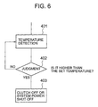
- Fig. 6 is a flowchart showing a control operation flow to cope with anomalous temperature in the air conditioning system of this invention.
- step 401 the temperature of the temperature sensor 29 is detected, and the temperature detection output is constantly supplied to the outlying temperature decision means 32.
- step 402 the outlying temperature decision means 32 makes a judgment as to whether the temperature detection output of the temperature sensor 29 is in excess of a pre-set temperature of, for example, 90°C.
- the procedure When it is not in excess of the pre-set temperature (i.e., when the answer in this step is NO), the procedure returns to step 401, and when it is (i.e., when the answer in this step is YES), an anomaly decision output is transmitted to the switch 33, and the switch 33 is opened in step 403 to turn off the electro-magnetic clutch. Alternatively, the anomaly decision output is supplied to the emergency stop means 34 to operate the same to thereby turn off the power of the air conditioning system 2.
- the above pre-set temperature serving as a reference for the outlying temperature decision means varies depending on the heat-generation object whose temperature is to be measured; the object may be the ball bearing, the armature friction plate, or the core.
- an appropriate reference temperature is set according to the heat-generation object.
- the reference temperature also depends on the mounting position of the temperature sensor 29, the core mold material, the distance between the temperature sensor and the heat-generation object, the dimensions, configuration, and structure of the electro-magnetic clutch, etc. Further, the difference between the core mold temperature and the temperature of the temperature sensor has also to be taken into account. In view of this, the pre-set reference temperature is determined by experiment.
- thermocouple a thermocouple
- resistance temperature sensor thermistor
- the temperature sensor also serves as the switch of the emergency stop means.
- the temperature sensor When the temperature sensor is mounted at a position where it is detachable, it is possible to replace the sensor whenever it is deteriorated.
- the sensor When the sensor is arranged in the periphery of the electro-magnetic clutch, it is possible to adopt a large sensor or an inexpensive, general purpose sensor, thus achieving a high degree of flexibility in the selection of the sensor and a reduction in the cost of checking the electro-magnetic clutch for anomalous heat generation.
Landscapes
- Engineering & Computer Science (AREA)
- General Engineering & Computer Science (AREA)
- Physics & Mathematics (AREA)
- Electromagnetism (AREA)
- Mechanical Engineering (AREA)
- Fluid Mechanics (AREA)
- Compressors, Vaccum Pumps And Other Relevant Systems (AREA)
- Compressor (AREA)
- Air-Conditioning For Vehicles (AREA)
- Hydraulic Clutches, Magnetic Clutches, Fluid Clutches, And Fluid Joints (AREA)
- Control Of Positive-Displacement Pumps (AREA)
- Applications Or Details Of Rotary Compressors (AREA)
- Air Conditioning Control Device (AREA)
Applications Claiming Priority (4)
| Application Number | Priority Date | Filing Date | Title |
|---|---|---|---|
| JP2000166984 | 2000-06-05 | ||
| JP2000166984 | 2000-06-05 | ||
| JP2000397034A JP4071932B2 (ja) | 2000-06-05 | 2000-12-27 | 気体圧縮機および空調システム |
| JP2000397034 | 2000-12-27 |
Publications (3)
| Publication Number | Publication Date |
|---|---|
| EP1162382A2 true EP1162382A2 (fr) | 2001-12-12 |
| EP1162382A3 EP1162382A3 (fr) | 2002-01-16 |
| EP1162382B1 EP1162382B1 (fr) | 2006-07-26 |
Family
ID=26593280
Family Applications (1)
| Application Number | Title | Priority Date | Filing Date |
|---|---|---|---|
| EP01304918A Expired - Lifetime EP1162382B1 (fr) | 2000-06-05 | 2001-06-05 | Compresseur à gaz et système de conditionnement d'air |
Country Status (7)
| Country | Link |
|---|---|
| US (1) | US6599102B2 (fr) |
| EP (1) | EP1162382B1 (fr) |
| JP (1) | JP4071932B2 (fr) |
| KR (1) | KR100756790B1 (fr) |
| CN (1) | CN100379994C (fr) |
| DE (1) | DE60121676T2 (fr) |
| MY (1) | MY127257A (fr) |
Cited By (2)
| Publication number | Priority date | Publication date | Assignee | Title |
|---|---|---|---|---|
| DE102006008510B4 (de) * | 2005-02-24 | 2010-06-17 | Sanden Corp., Isesaki | Elektromagnetische Kupplung für einen Kompressor |
| EP2372154A2 (fr) | 2010-03-17 | 2011-10-05 | Valeo Compressor Europe, s.r.o. | Capteur de vitesse |
Families Citing this family (7)
| Publication number | Priority date | Publication date | Assignee | Title |
|---|---|---|---|---|
| JP3964812B2 (ja) * | 2003-03-11 | 2007-08-22 | サンデン株式会社 | 圧縮機用電磁クラッチ |
| JP2006250436A (ja) * | 2005-03-10 | 2006-09-21 | Yanmar Co Ltd | エンジン駆動式ヒートポンプ |
| JP2010091071A (ja) * | 2008-10-10 | 2010-04-22 | Denso Corp | 電磁クラッチ |
| JP2010101582A (ja) * | 2008-10-24 | 2010-05-06 | Mitsubishi Heavy Ind Ltd | 輸送用冷凍装置 |
| US20130343912A1 (en) * | 2011-03-11 | 2013-12-26 | Ulvac Kiko, Inc. | Vacuum pump, vacuum exhaust device, and method of operating vacuum pump |
| KR102015321B1 (ko) * | 2013-07-11 | 2019-08-29 | 한온시스템 주식회사 | 전자석 클러치용 전원공급 스위칭 커넥터 |
| CN112739920B (zh) | 2018-07-31 | 2023-06-30 | 江森自控泰科知识产权控股有限责任合伙公司 | 主动轴承温度控制 |
Family Cites Families (16)
| Publication number | Priority date | Publication date | Assignee | Title |
|---|---|---|---|---|
| JPS5835887B2 (ja) | 1975-06-25 | 1983-08-05 | 日産自動車株式会社 | ジドウクラツチニオケルクラツチバンノ マサツケイスウホシヨウソウチ |
| JPS5660733A (en) | 1979-10-22 | 1981-05-25 | Fuji Heavy Ind Ltd | Antiseizing device of electromagnetic powder type clutch for vehicle |
| JPS5737022A (en) * | 1980-08-15 | 1982-03-01 | Fuji Heavy Ind Ltd | Overheat preventive device of electromagnetic clutch for vehicle |
| US4423683A (en) * | 1981-12-28 | 1984-01-03 | The United States Of America As Represented By The Secretary Of The Navy | Enclosure for a warhead case |
| JPS61178216A (ja) * | 1985-02-01 | 1986-08-09 | Sanden Corp | 車輛用空調装置における可変容量圧縮機の制御装置 |
| KR940001991B1 (ko) * | 1986-02-03 | 1994-03-12 | 산덴 가부시기가이샤 | 전자기 클러치 |
| JPS62184916A (ja) * | 1986-02-07 | 1987-08-13 | Sanden Corp | 可変容量圧縮機を有する冷房装置 |
| US5094332A (en) | 1990-12-31 | 1992-03-10 | Dana Corporation | Digital control system for electromagnetic clutch |
| US5146763A (en) * | 1991-03-18 | 1992-09-15 | General Motors Corporation | Air conditioning compressor protection device |
| US5404980A (en) * | 1994-04-11 | 1995-04-11 | Ford Motor Company | Electromagnetic clutch with failure protection apparatus |
| US5497870A (en) * | 1994-06-10 | 1996-03-12 | Ogura Clutch Co., Ltd. | Electromagnetic clutch slip protection system |
| JP3627313B2 (ja) * | 1995-03-29 | 2005-03-09 | 株式会社デンソー | 電磁クラッチ |
| JP3837786B2 (ja) | 1996-09-12 | 2006-10-25 | 株式会社デンソー | 電磁クラッチ |
| KR19980030820U (ko) * | 1996-11-29 | 1998-08-17 | 양재신 | 소착방지장치가 구비된 컴프레서 |
| JP3925880B2 (ja) * | 1998-01-19 | 2007-06-06 | 小倉クラッチ株式会社 | 電磁クラッチ |
| JP3941242B2 (ja) * | 1998-07-07 | 2007-07-04 | 株式会社デンソー | 電磁クラッチ |
-
2000
- 2000-12-27 JP JP2000397034A patent/JP4071932B2/ja not_active Expired - Fee Related
-
2001
- 2001-06-01 MY MYPI20012617 patent/MY127257A/en unknown
- 2001-06-04 US US09/873,609 patent/US6599102B2/en not_active Expired - Lifetime
- 2001-06-05 KR KR1020010031365A patent/KR100756790B1/ko not_active Expired - Fee Related
- 2001-06-05 DE DE60121676T patent/DE60121676T2/de not_active Expired - Lifetime
- 2001-06-05 CN CNB01123394XA patent/CN100379994C/zh not_active Expired - Fee Related
- 2001-06-05 EP EP01304918A patent/EP1162382B1/fr not_active Expired - Lifetime
Cited By (2)
| Publication number | Priority date | Publication date | Assignee | Title |
|---|---|---|---|---|
| DE102006008510B4 (de) * | 2005-02-24 | 2010-06-17 | Sanden Corp., Isesaki | Elektromagnetische Kupplung für einen Kompressor |
| EP2372154A2 (fr) | 2010-03-17 | 2011-10-05 | Valeo Compressor Europe, s.r.o. | Capteur de vitesse |
Also Published As
| Publication number | Publication date |
|---|---|
| US6599102B2 (en) | 2003-07-29 |
| DE60121676T2 (de) | 2007-08-02 |
| CN1330227A (zh) | 2002-01-09 |
| DE60121676D1 (de) | 2006-09-07 |
| KR20010110207A (ko) | 2001-12-12 |
| US20020001533A1 (en) | 2002-01-03 |
| MY127257A (en) | 2006-11-30 |
| KR100756790B1 (ko) | 2007-09-07 |
| CN100379994C (zh) | 2008-04-09 |
| JP2002061572A (ja) | 2002-02-28 |
| JP4071932B2 (ja) | 2008-04-02 |
| EP1162382A3 (fr) | 2002-01-16 |
| EP1162382B1 (fr) | 2006-07-26 |
Similar Documents
| Publication | Publication Date | Title |
|---|---|---|
| EP1162382B1 (fr) | Compresseur à gaz et système de conditionnement d'air | |
| US5295038A (en) | Electromagnetic clutch | |
| US8517698B2 (en) | Air conditioning compressor over-torque protector | |
| US5931008A (en) | Protecting device for car air conditioner | |
| JP2012117551A (ja) | 電磁クラッチ | |
| WO2014156062A1 (fr) | Mécanisme d'embrayage | |
| CN100366938C (zh) | 车辆和用于这种车辆的压缩机的电磁离合器 | |
| US7455160B2 (en) | Electromagnetic clutch | |
| US7367439B2 (en) | Electromagnetic clutch with elastic member easily melted | |
| JPS5913137A (ja) | 自動車空調用電磁クラツチ装置 | |
| KR101508235B1 (ko) | 전자클러치의 필드코일 어셈블리 | |
| KR100747736B1 (ko) | 팬 구동 모니터링 장치 및 그 방법 | |
| JP2000230579A (ja) | 電磁クラッチ | |
| JPH07139564A (ja) | 電磁クラッチの異常検出装置 | |
| CN109923325B (zh) | 电磁离合器及包括该电磁离合器的压缩机 | |
| JP2006242131A (ja) | 圧縮機の保護装置 | |
| KR200162259Y1 (ko) | 압축기의 전자클러치 온도감지장치 | |
| JP2005337450A (ja) | 電磁クラッチ | |
| US4125180A (en) | Disconnect mechanism for compressor drive | |
| JP6606972B2 (ja) | 動力伝達装置 | |
| JP2006250436A (ja) | エンジン駆動式ヒートポンプ | |
| JPH0712141A (ja) | 電磁クラッチおよび電磁クラッチの異常検出システム | |
| JP2009068342A (ja) | プーリ付き圧縮機 | |
| JP2010091071A (ja) | 電磁クラッチ | |
| JPH04181027A (ja) | 電磁クラッチ装置 |
Legal Events
| Date | Code | Title | Description |
|---|---|---|---|
| PUAI | Public reference made under article 153(3) epc to a published international application that has entered the european phase |
Free format text: ORIGINAL CODE: 0009012 |
|
| PUAL | Search report despatched |
Free format text: ORIGINAL CODE: 0009013 |
|
| AK | Designated contracting states |
Kind code of ref document: A2 Designated state(s): AT BE CH CY DE DK ES FI FR GB GR IE IT LI LU MC NL PT SE TR Kind code of ref document: A2 Designated state(s): DE FR |
|
| AX | Request for extension of the european patent |
Free format text: AL;LT;LV;MK;RO;SI |
|
| AK | Designated contracting states |
Kind code of ref document: A3 Designated state(s): AT BE CH CY DE DK ES FI FR GB GR IE IT LI LU MC NL PT SE TR |
|
| AX | Request for extension of the european patent |
Free format text: AL;LT;LV;MK;RO;SI |
|
| RIC1 | Information provided on ipc code assigned before grant |
Free format text: 7F 16D 27/14 A, 7F 16D 48/06 B, 7F 16D 27/06 B |
|
| 17P | Request for examination filed |
Effective date: 20020711 |
|
| AKX | Designation fees paid |
Free format text: DE FR |
|
| RAP1 | Party data changed (applicant data changed or rights of an application transferred) |
Owner name: CALSONIC COMPRESSOR MANUFACTURING INC. |
|
| 17Q | First examination report despatched |
Effective date: 20050427 |
|
| GRAP | Despatch of communication of intention to grant a patent |
Free format text: ORIGINAL CODE: EPIDOSNIGR1 |
|
| GRAS | Grant fee paid |
Free format text: ORIGINAL CODE: EPIDOSNIGR3 |
|
| GRAA | (expected) grant |
Free format text: ORIGINAL CODE: 0009210 |
|
| AK | Designated contracting states |
Kind code of ref document: B1 Designated state(s): DE FR |
|
| REF | Corresponds to: |
Ref document number: 60121676 Country of ref document: DE Date of ref document: 20060907 Kind code of ref document: P |
|
| ET | Fr: translation filed | ||
| PLBE | No opposition filed within time limit |
Free format text: ORIGINAL CODE: 0009261 |
|
| STAA | Information on the status of an ep patent application or granted ep patent |
Free format text: STATUS: NO OPPOSITION FILED WITHIN TIME LIMIT |
|
| 26N | No opposition filed |
Effective date: 20070427 |
|
| REG | Reference to a national code |
Ref country code: FR Ref legal event code: PLFP Year of fee payment: 16 |
|
| PGFP | Annual fee paid to national office [announced via postgrant information from national office to epo] |
Ref country code: DE Payment date: 20160601 Year of fee payment: 16 |
|
| PGFP | Annual fee paid to national office [announced via postgrant information from national office to epo] |
Ref country code: FR Payment date: 20160516 Year of fee payment: 16 |
|
| REG | Reference to a national code |
Ref country code: DE Ref legal event code: R119 Ref document number: 60121676 Country of ref document: DE |
|
| REG | Reference to a national code |
Ref country code: FR Ref legal event code: ST Effective date: 20180228 |
|
| PG25 | Lapsed in a contracting state [announced via postgrant information from national office to epo] |
Ref country code: DE Free format text: LAPSE BECAUSE OF NON-PAYMENT OF DUE FEES Effective date: 20180103 |
|
| PG25 | Lapsed in a contracting state [announced via postgrant information from national office to epo] |
Ref country code: FR Free format text: LAPSE BECAUSE OF NON-PAYMENT OF DUE FEES Effective date: 20170630 |