EP1162680A2 - Dispositif et méthode pour humidifier un courant de gaz ainsi que l'utilisation du dispositif - Google Patents
Dispositif et méthode pour humidifier un courant de gaz ainsi que l'utilisation du dispositif Download PDFInfo
- Publication number
- EP1162680A2 EP1162680A2 EP01112522A EP01112522A EP1162680A2 EP 1162680 A2 EP1162680 A2 EP 1162680A2 EP 01112522 A EP01112522 A EP 01112522A EP 01112522 A EP01112522 A EP 01112522A EP 1162680 A2 EP1162680 A2 EP 1162680A2
- Authority
- EP
- European Patent Office
- Prior art keywords
- heat exchanger
- liquid
- process gas
- gas
- cooling fins
- Prior art date
- Legal status (The legal status is an assumption and is not a legal conclusion. Google has not performed a legal analysis and makes no representation as to the accuracy of the status listed.)
- Granted
Links
- 238000000034 method Methods 0.000 title claims abstract description 70
- 239000007789 gas Substances 0.000 claims abstract description 100
- 239000007788 liquid Substances 0.000 claims abstract description 42
- 239000007921 spray Substances 0.000 claims abstract description 19
- 239000000446 fuel Substances 0.000 claims abstract description 17
- 238000001704 evaporation Methods 0.000 claims abstract description 12
- 238000010438 heat treatment Methods 0.000 claims abstract description 3
- XLYOFNOQVPJJNP-UHFFFAOYSA-N water Substances O XLYOFNOQVPJJNP-UHFFFAOYSA-N 0.000 claims description 50
- 238000001816 cooling Methods 0.000 claims description 43
- 238000012546 transfer Methods 0.000 claims description 34
- 238000004581 coalescence Methods 0.000 claims description 6
- 239000000203 mixture Substances 0.000 claims description 3
- 238000005507 spraying Methods 0.000 claims description 2
- 238000013016 damping Methods 0.000 claims 1
- 230000008020 evaporation Effects 0.000 abstract description 8
- 239000012528 membrane Substances 0.000 description 18
- 238000000889 atomisation Methods 0.000 description 4
- UFHFLCQGNIYNRP-UHFFFAOYSA-N Hydrogen Chemical compound [H][H] UFHFLCQGNIYNRP-UHFFFAOYSA-N 0.000 description 3
- 230000002349 favourable effect Effects 0.000 description 3
- 239000001257 hydrogen Substances 0.000 description 3
- 229910052739 hydrogen Inorganic materials 0.000 description 3
- 238000007710 freezing Methods 0.000 description 2
- 230000008014 freezing Effects 0.000 description 2
- 238000002347 injection Methods 0.000 description 2
- 239000007924 injection Substances 0.000 description 2
- 238000005259 measurement Methods 0.000 description 2
- 238000005457 optimization Methods 0.000 description 2
- 238000012549 training Methods 0.000 description 2
- 229910000838 Al alloy Inorganic materials 0.000 description 1
- 229910000831 Steel Inorganic materials 0.000 description 1
- 230000006978 adaptation Effects 0.000 description 1
- 230000002528 anti-freeze Effects 0.000 description 1
- 239000003795 chemical substances by application Substances 0.000 description 1
- 238000011109 contamination Methods 0.000 description 1
- 239000002826 coolant Substances 0.000 description 1
- 238000005260 corrosion Methods 0.000 description 1
- 230000007797 corrosion Effects 0.000 description 1
- 230000001419 dependent effect Effects 0.000 description 1
- 238000010586 diagram Methods 0.000 description 1
- 238000009826 distribution Methods 0.000 description 1
- 238000002474 experimental method Methods 0.000 description 1
- 239000012530 fluid Substances 0.000 description 1
- 239000012535 impurity Substances 0.000 description 1
- 239000007791 liquid phase Substances 0.000 description 1
- 239000000463 material Substances 0.000 description 1
- 239000002245 particle Substances 0.000 description 1
- 239000005518 polymer electrolyte Substances 0.000 description 1
- 238000004886 process control Methods 0.000 description 1
- 238000006057 reforming reaction Methods 0.000 description 1
- 229920006395 saturated elastomer Polymers 0.000 description 1
- 239000007787 solid Substances 0.000 description 1
- 239000007858 starting material Substances 0.000 description 1
- 239000010959 steel Substances 0.000 description 1
- 238000003860 storage Methods 0.000 description 1
- 238000011144 upstream manufacturing Methods 0.000 description 1
- 239000002918 waste heat Substances 0.000 description 1
Images
Classifications
-
- H—ELECTRICITY
- H01—ELECTRIC ELEMENTS
- H01M—PROCESSES OR MEANS, e.g. BATTERIES, FOR THE DIRECT CONVERSION OF CHEMICAL ENERGY INTO ELECTRICAL ENERGY
- H01M8/00—Fuel cells; Manufacture thereof
- H01M8/04—Auxiliary arrangements, e.g. for control of pressure or for circulation of fluids
- H01M8/04082—Arrangements for control of reactant parameters, e.g. pressure or concentration
- H01M8/04089—Arrangements for control of reactant parameters, e.g. pressure or concentration of gaseous reactants
- H01M8/04119—Arrangements for control of reactant parameters, e.g. pressure or concentration of gaseous reactants with simultaneous supply or evacuation of electrolyte; Humidifying or dehumidifying
- H01M8/04126—Humidifying
-
- F—MECHANICAL ENGINEERING; LIGHTING; HEATING; WEAPONS; BLASTING
- F28—HEAT EXCHANGE IN GENERAL
- F28C—HEAT-EXCHANGE APPARATUS, NOT PROVIDED FOR IN ANOTHER SUBCLASS, IN WHICH THE HEAT-EXCHANGE MEDIA COME INTO DIRECT CONTACT WITHOUT CHEMICAL INTERACTION
- F28C3/00—Other direct-contact heat-exchange apparatus
- F28C3/06—Other direct-contact heat-exchange apparatus the heat-exchange media being a liquid and a gas or vapour
- F28C3/08—Other direct-contact heat-exchange apparatus the heat-exchange media being a liquid and a gas or vapour with change of state, e.g. absorption, evaporation, condensation
-
- F—MECHANICAL ENGINEERING; LIGHTING; HEATING; WEAPONS; BLASTING
- F28—HEAT EXCHANGE IN GENERAL
- F28D—HEAT-EXCHANGE APPARATUS, NOT PROVIDED FOR IN ANOTHER SUBCLASS, IN WHICH THE HEAT-EXCHANGE MEDIA DO NOT COME INTO DIRECT CONTACT
- F28D9/00—Heat-exchange apparatus having stationary plate-like or laminated conduit assemblies for both heat-exchange media, the media being in contact with different sides of a conduit wall
- F28D9/0062—Heat-exchange apparatus having stationary plate-like or laminated conduit assemblies for both heat-exchange media, the media being in contact with different sides of a conduit wall the conduits for one heat-exchange medium being formed by spaced plates with inserted elements
-
- F—MECHANICAL ENGINEERING; LIGHTING; HEATING; WEAPONS; BLASTING
- F28—HEAT EXCHANGE IN GENERAL
- F28F—DETAILS OF HEAT-EXCHANGE AND HEAT-TRANSFER APPARATUS, OF GENERAL APPLICATION
- F28F3/00—Plate-like or laminated elements; Assemblies of plate-like or laminated elements
- F28F3/02—Elements or assemblies thereof with means for increasing heat-transfer area, e.g. with fins, with recesses, with corrugations
-
- H—ELECTRICITY
- H01—ELECTRIC ELEMENTS
- H01M—PROCESSES OR MEANS, e.g. BATTERIES, FOR THE DIRECT CONVERSION OF CHEMICAL ENERGY INTO ELECTRICAL ENERGY
- H01M8/00—Fuel cells; Manufacture thereof
- H01M8/04—Auxiliary arrangements, e.g. for control of pressure or for circulation of fluids
- H01M8/04007—Auxiliary arrangements, e.g. for control of pressure or for circulation of fluids related to heat exchange
- H01M8/04067—Heat exchange or temperature measuring elements, thermal insulation, e.g. heat pipes, heat pumps, fins
- H01M8/04074—Heat exchange unit structures specially adapted for fuel cell
-
- F—MECHANICAL ENGINEERING; LIGHTING; HEATING; WEAPONS; BLASTING
- F28—HEAT EXCHANGE IN GENERAL
- F28F—DETAILS OF HEAT-EXCHANGE AND HEAT-TRANSFER APPARATUS, OF GENERAL APPLICATION
- F28F2250/00—Arrangements for modifying the flow of the heat exchange media, e.g. flow guiding means; Particular flow patterns
- F28F2250/10—Particular pattern of flow of the heat exchange media
- F28F2250/102—Particular pattern of flow of the heat exchange media with change of flow direction
-
- H—ELECTRICITY
- H01—ELECTRIC ELEMENTS
- H01M—PROCESSES OR MEANS, e.g. BATTERIES, FOR THE DIRECT CONVERSION OF CHEMICAL ENERGY INTO ELECTRICAL ENERGY
- H01M8/00—Fuel cells; Manufacture thereof
- H01M8/04—Auxiliary arrangements, e.g. for control of pressure or for circulation of fluids
- H01M8/04007—Auxiliary arrangements, e.g. for control of pressure or for circulation of fluids related to heat exchange
- H01M8/04029—Heat exchange using liquids
-
- Y—GENERAL TAGGING OF NEW TECHNOLOGICAL DEVELOPMENTS; GENERAL TAGGING OF CROSS-SECTIONAL TECHNOLOGIES SPANNING OVER SEVERAL SECTIONS OF THE IPC; TECHNICAL SUBJECTS COVERED BY FORMER USPC CROSS-REFERENCE ART COLLECTIONS [XRACs] AND DIGESTS
- Y02—TECHNOLOGIES OR APPLICATIONS FOR MITIGATION OR ADAPTATION AGAINST CLIMATE CHANGE
- Y02E—REDUCTION OF GREENHOUSE GAS [GHG] EMISSIONS, RELATED TO ENERGY GENERATION, TRANSMISSION OR DISTRIBUTION
- Y02E60/00—Enabling technologies; Technologies with a potential or indirect contribution to GHG emissions mitigation
- Y02E60/30—Hydrogen technology
- Y02E60/50—Fuel cells
Definitions
- the invention relates to an apparatus and a method for Humidify a gas stream and use the device according to the preambles of the independent claims.
- EP 0 629 014 B1 describes a method for moistening Process gas known for the operation of fuel cells, in which finely atomized water in a predetermined amount with the help an injector from a supply line into a Gas supply line of the fuel cell is injected.
- a setpoint for the amount of water to be supplied is given in Dependence on operating parameters determined and the The amount of water is metered exactly so that a sets the desired humidity of the process gases.
- Water is fed directly into the gas stream by atomization using an injection nozzle.
- the maximum permissible droplet size must be due to the geometry of the Gas guide channels of the fuel cell are determined so that the droplets have no cross sections in the area of the fuel cell can clog.
- the known devices for humidifying process gases such as Air or hydrogen are usually heavy and large. Usually, the media must enter the Humidifier can be cooled. On the other hand, a medium freezes in Humidifier, the humidifier will be damaged.
- the device according to the invention enables humidification by evaporation at low temperatures by direct Heat conduction without complex process control.
- Another Advantage of the invention is that that to be evaporated Medium in a humidifier very finely and evenly distributed becomes, which makes the evaporation process more efficient.
- the Device can handle both media with high temperatures operated as well as without problems with freezing point work.
- the pressure loss in the device is advantageous low.
- the invention is particularly suitable for a gas flow moisturize.
- One according to the invention is particularly preferred Humidifier device in a fuel cell system used to humidify process gases.
- Humidification is e.g. for the cathode inlet or also for a medium supplied to the anode is necessary to meet the water needs a membrane of a polymer electrolyte fuel cell ensure, or also to moisten a starting material in order to a reforming reaction to gain a hydrogen-containing reformate in a gas generation system to support a fuel cell system.
- the invention is based on a preferred Fuel cell system described, however, is based on this Use not restricted.
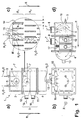
- Fig. 1 is a schematic diagram of a preferred Training of the device according to the invention in several Shown views.
- the humidifier device 1 in Fig. 1a consists of three sections, a spray chamber 2, one Heat exchanger area 3 and a liquid separator area or water separator area 4.
- humidifier devices will directly heat from one Heat transfer medium to the liquid to be evaporated, preferably water.
- the liquid covered a relatively large surface of a heat exchanger in the Inside the device.
- liquid water H 2 O
- spray chamber 2 forms the gas supply line for the process gas 7 into the humidifier device 1.
- the process gas 7 is fed to the humidifier 1 through a process gas supply 8 in the area of the spray chamber 2 and discharged from the humidifier 1 through a process gas outlet 9 in the area of the heat transfer area 3.
- the heat exchanger area 3 means 10, 11, 12, 14, 15 for Heating the liquid is provided. In doing so, a Heat transfer medium 10 via a heat transfer medium feed 11 fed and via a heat transfer medium outlet 12 from the Heat exchanger area 3 removed. Related to the The flow direction of the water is the Heat transfer medium supply 11 downstream of the heat transfer medium outlet 12. In the heat exchanger area 3, the liquid at least partially evaporated.
- the liquid or water is preferably supplied for humidifying the gas stream in the gas stream of the process gas.
- the liquid is supplied in an amount which is greater than the theoretically necessary amount to make one achieve relative humidity of 100%.
- a distance in Direction of flow R after the supply of the liquid is in residual liquid remaining in its liquid phase separated the gas streams.
- the heat exchanger area 3 has a large number of Flow channels for the gas stream to be humidified.
- the Flow channels are at least partially covered by cooling fins 14 with heat exchanger surfaces 15 for at least partial evaporation of the liquid formed.
- the droplets T are from the process gas carried away and from the spray chamber 2 in the Heat exchanger area 3 transported.
- Heat exchanger area 3 are a plurality of cooling fins 14 arranged. Form the surfaces 15 of the cooling fins 14 Heat exchanger surfaces 15 and divide the gas flow into one A plurality of parallel flow channels with one Flow direction R.
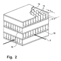
- the cooling fins 14 are preferably by means of heat conduction heated by a heat transfer medium 10. This is in Fig. 2 shown based on a detail of the heat exchanger area 3. Staggered cooling fins 14 are layered arranged. A plurality of such layers are arranged one above the other. Between these layers one can Flow heat transfer medium 10. Heat can be generated by conduction over the cooling fins 14 and the boundaries 18 of the cooling fin layers be delivered.
- FIG. 1c the flow channels between the cooling fins 14 in the heat exchanger area 3 as an enlarged detail of FIG. 1a shown in detail.
- the view corresponds to a top view of a layer of cooling fins 14.
- the cooling fins 14 are preferably in several, in Flow direction of the water successive, to each other staggered rows R1, R2, ... arranged. In every row R1, R2, ... are a plurality of cooling fins 14 with a height h closely spaced by a distance s.
- the cooling fins 14 lead to a very large inner Surface of the heat exchanger area 3.
- the arrangement is in Fig. 2nd shown schematically.
- too other types of heat exchanger arrangements in the Heat exchanger area 3 may be provided, such as plates, tube bundles Etc.
- the geometry of the cooling fins 14 and the size the droplets suitably matched.
- a preferred distance s between adjacent cooling fins 14 is less than 1 mm, especially preferably 0.9 mm.
- a preferred droplet size is at about 50 ⁇ m in diameter.
- Water droplets T in the gas stream of the process gas 7 are entrained, at least remain in the heat exchanger area 3 hang partially on the surface 15 of the cooling fins 14. Droplets T are from the process gas 7 in the heat exchanger area 3 swept away. When entering the area of the cooling fins 14 form microturbulences M, which adhere to Reinforce droplets T on the surface 15 of the cooling fins 14.
- the amount of water supplied to the spray chamber 2 is Expediently so large that the process gas 7 is saturated.
- the amount of water is advantageously a multiple of that minimum necessary amount, so that regulation or control the water supply can be omitted. Excess water will simply caught in the water separator 4, which is attached to the Heat exchanger area 3 connects.
- the water droplets T with different suitable means can be generated, such as by means of Atomization by pressure, pneumatic, mechanical or vacuum, the number of nozzles and their arrangement can also vary become.
- suitable means such as by means of Atomization by pressure, pneumatic, mechanical or vacuum, the number of nozzles and their arrangement can also vary become.
- the material for select the heat exchanger area accordingly, for example corrosion-resistant steels or aluminum alloys, preferably AL-3003, when humidifying hydrogen and the like.
- a chevron separator can advantageously perform two functions fulfill. On the one hand, it is suitable for droplets T with a separating supercritical size, on the other hand it prevents an undesirable movement of water in the bottom area 4 of the Humidifier 1.
- Fig. 1d is a flow path of the process gas 7 within the Device 1 shown.
- the flow path runs between Process gas supply 8 and process gas outlet 9 by the process gas first through the spray chamber 2, then through the Heat exchanger area 3, then in the liquid separator 4th and from the liquid separator 4 to the process gas outlet 9 becomes.
- a coalescence filter can advantageously be provided at the process gas outlet 9 be provided for separating gas and droplets.
- the humidified process gas is at the outlet 9 of the device in essentially free of water droplets T above one critical size.
- Heat transfer media 10 media are preferably used as the heat transfer medium Excess heat from the coolant, not shown Drain the fuel cell system.
- the temperature of one Heat transfer medium 10 is sufficient for evaporation in Heat exchanger area 3 off.
- heat transfer media 10 used whose temperatures are above the temperatures of such Cooling media in the fuel cell system can Humidifier 1 can be made smaller in size.
- electrical or thermal Agents are additionally heated to a higher temperature.
- Another inexpensive measure is the optimization of the Dimensions of the heat exchanger area 3 by on the Gas inlet side 8 of the process gas 7 means are provided to to homogenize the gas distribution.
- baffles 16 favorable, which are arranged in the spray chamber 2 and the Influence flow of the process gas 7 so that the gas flow itself can distribute as homogeneously as possible.
- Another cheap one is the optimization of the dimensions and arrangement of the heat transfer medium circuit 11, 12.
- a optimized humidifier 1 according to the invention up to 70% smaller and up to 80% lighter than a comparable membrane humidifier. This is particularly important when using the humidifier 1 according to the invention in mobile Fuel cell systems an advantage.
- a humidifier 1 according to the invention can be up to 90% cheaper than a membrane humidifier.
- the device according to the invention is that the reliability of the humidifier is improved, because fewer components are required.
- the Device in contrast to membrane humidifiers, also with considerable pressure differences between the heat transfer medium 10 and Process gas 7 work.
- the humidifier 1 according to the invention is in the essentially leak-free or easy to seal and can without further also temperatures below the freezing point of Exposed to water without damage.
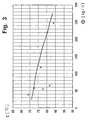
- Fig. 3 is a comparison between an inventive Humidifier 1 and a membrane humidifier shown.
- the Dew point ⁇ of a process gas 7 is dependent on the Flow ⁇ of the process gas 7 applied.
- the values of Membrane humidifiers are shown by the solid line represents.
- the dots represent measurement data that are on a Process gas 7 were measured, which with a humidifier 1 of the invention was moistened.
- process parameters as Heat carrier temperature, process gas temperature, process gas pressure used.
- Water or else can advantageously be used as the heat transfer medium 10
- the cooling system for that Fuel cell system can be designed smaller because Waste heat from the system at the humidifier 1 can be used.
- the humidifier 1 according to the invention is particularly suitable for the Use in fuel cell systems where humidification at a low process gas temperature.
Landscapes
- Engineering & Computer Science (AREA)
- Mechanical Engineering (AREA)
- General Engineering & Computer Science (AREA)
- Physics & Mathematics (AREA)
- Thermal Sciences (AREA)
- Life Sciences & Earth Sciences (AREA)
- Manufacturing & Machinery (AREA)
- Sustainable Development (AREA)
- Sustainable Energy (AREA)
- Chemical & Material Sciences (AREA)
- Chemical Kinetics & Catalysis (AREA)
- Electrochemistry (AREA)
- General Chemical & Material Sciences (AREA)
- Fuel Cell (AREA)
- Air Humidification (AREA)
- Heat-Exchange Devices With Radiators And Conduit Assemblies (AREA)
Applications Claiming Priority (2)
| Application Number | Priority Date | Filing Date | Title |
|---|---|---|---|
| DE10028133 | 2000-06-07 | ||
| DE10028133A DE10028133B4 (de) | 2000-06-07 | 2000-06-07 | Vorrichtung und Verfahren zum Befeuchten eines Prozessgasstroms sowie Verwendung der Vorrichtung |
Publications (3)
| Publication Number | Publication Date |
|---|---|
| EP1162680A2 true EP1162680A2 (fr) | 2001-12-12 |
| EP1162680A3 EP1162680A3 (fr) | 2007-02-21 |
| EP1162680B1 EP1162680B1 (fr) | 2010-11-24 |
Family
ID=7644956
Family Applications (1)
| Application Number | Title | Priority Date | Filing Date |
|---|---|---|---|
| EP01112522A Expired - Lifetime EP1162680B1 (fr) | 2000-06-07 | 2001-05-23 | Dispositif et méthode pour humidifier un courant de gaz ainsi que l'utilisation du dispositif |
Country Status (4)
| Country | Link |
|---|---|
| US (1) | US6699608B2 (fr) |
| EP (1) | EP1162680B1 (fr) |
| JP (1) | JP3667253B2 (fr) |
| DE (2) | DE10028133B4 (fr) |
Cited By (6)
| Publication number | Priority date | Publication date | Assignee | Title |
|---|---|---|---|---|
| WO2005043046A1 (fr) * | 2003-11-03 | 2005-05-12 | Hydrogenics Corporation | Dispositif de regulation de l'humidite |
| WO2005101562A1 (fr) * | 2004-03-31 | 2005-10-27 | Modine Manufacturing Company | Humidificateur de combustible et prechauffeur destine a etre utilise dans un systeme de pile a combustible |
| EP1365465A3 (fr) * | 2002-04-03 | 2007-02-14 | Modine Manufacturing Company | Système de pile à combustible et corps de chauffage / humidificateur utilisé par celui-ci |
| EP1536185A4 (fr) * | 2002-07-18 | 2009-09-02 | Sumitomo Prec Products Company | Humidificateur de gaz |
| US8245491B2 (en) | 2006-11-15 | 2012-08-21 | Modine Manufacturing Company | Heat recovery system and method |
| CN109623261A (zh) * | 2019-01-25 | 2019-04-16 | 尹苑苑 | 一种电机转子热套转轴冷却机 |
Families Citing this family (26)
| Publication number | Priority date | Publication date | Assignee | Title |
|---|---|---|---|---|
| KR20020055963A (ko) * | 2000-12-29 | 2002-07-10 | 박호군 | 고분자 전해질 연료전지 운전용 가습장치 |
| US20040258968A1 (en) * | 2003-03-21 | 2004-12-23 | Voss Mark G. | Cathode inlet gas humidification system and method for a fuel cell system |
| US7910255B2 (en) * | 2003-08-15 | 2011-03-22 | GM Global Technology Operations LLC | Charge air humidification for fuel cells |
| JP2007503295A (ja) * | 2003-08-26 | 2007-02-22 | ハイドロジェニクス コーポレイション | 流体分離器と一体化したエネルギー及び/又は質量交換器 |
| CN100459257C (zh) * | 2003-09-15 | 2009-02-04 | 亚太燃料电池科技股份有限公司 | 具有反应气体温度和湿度调节装置的燃料电池系统 |
| JP5019822B2 (ja) * | 2005-08-19 | 2012-09-05 | モーディーン・マニュファクチャリング・カンパニー | 中間の蒸気過熱経路を備える水蒸発器 |
| US8171985B2 (en) * | 2005-08-19 | 2012-05-08 | Modine Manufacturing Company | Water vaporizer with intermediate steam superheating pass |
| KR100654330B1 (ko) * | 2005-12-23 | 2006-12-08 | 한국과학기술연구원 | 증발식 연료전지 가습기 |
| DE602006020790D1 (fr) * | 2006-09-13 | 2011-04-28 | Daimler Ag | |
| NO20081799L (no) * | 2008-04-14 | 2009-10-15 | Rotoboost As | Fremgangsmate og anordning for varme og kuldeproduksjon |
| JP5397107B2 (ja) * | 2009-09-09 | 2014-01-22 | 株式会社デンソー | 調湿換気装置 |
| US9059600B2 (en) | 2011-06-27 | 2015-06-16 | Bloom Energy Corporation | Convergent energized IT apparatus for residential use |
| US9462724B2 (en) * | 2011-06-27 | 2016-10-04 | Bloom Energy Corporation | Convergent energized IT apparatus for commercial use |
| DE102013007207A1 (de) * | 2013-04-25 | 2014-10-30 | Daimler Ag | Vorrichtung zur Aufbereitung von Luft |
| DE202013009357U1 (de) | 2013-06-27 | 2015-01-16 | Dana Canada Corporation | Integrierte Gasmanagementvorrichtung für ein Brennstoffzellensystem |
| US10052449B2 (en) | 2014-03-21 | 2018-08-21 | Fisher & Paykel Healthcare Limited | Heating arrangements for humidification systems |
| US10396039B2 (en) | 2014-12-09 | 2019-08-27 | Mitsubishi Electric Corporation | Semiconductor package |
| DE102015218769A1 (de) | 2015-09-29 | 2017-03-30 | Volkswagen Ag | Feuchteübertrager sowie Brennstoffzellensystem und Fahrzeug mit einem solchen |
| EP3168561A1 (fr) * | 2015-11-11 | 2017-05-17 | Air To Air Sweden AB | Dispositif d'échange de chaleur et/ou de transfert de masse entre des débits de fluide |
| SG11201805302UA (en) * | 2015-12-23 | 2018-07-30 | Fisher & Paykel Healthcare Ltd | Heating arrangements for humidification systems |
| JP2018116848A (ja) * | 2017-01-18 | 2018-07-26 | 株式会社デンソー | 燃料電池システム |
| CN109546180B (zh) * | 2019-01-10 | 2024-04-12 | 中氢新能技术有限公司 | 一种燃料电池加热装置 |
| SE546643C2 (en) * | 2022-02-22 | 2025-01-07 | Grimaldi Dev Ab | A fuel cell stack arrangement comprising a separating unit, and a method for treatment of cathode intake air using a separating unit |
| CN116404197B (zh) * | 2023-05-30 | 2026-02-17 | 北京亿华通科技股份有限公司 | 一种具有增湿器和中冷器功能的喷雾蒸发腔及其系统 |
| CN116697733B (zh) * | 2023-06-29 | 2024-04-05 | 安徽森米诺智能装备有限公司 | 一种气液两相余热回收工艺、设备及在粮食干燥的应用 |
| DE102023127257A1 (de) * | 2023-10-06 | 2025-04-10 | Quantron Ag | Brennstoffzellenfahrzeug mit einem Zyklonabscheider und Verfahren zum Befeuchten einströmender Außenluft |
Citations (6)
| Publication number | Priority date | Publication date | Assignee | Title |
|---|---|---|---|---|
| US3366158A (en) | 1966-05-12 | 1968-01-30 | Rosenblad Corp | Falling film evaporator |
| DE3811852A1 (de) | 1987-08-04 | 1989-02-16 | Toshiba Kawasaki Kk | Waermetauscher |
| US4973530A (en) | 1989-12-21 | 1990-11-27 | The United States Of America As Represented By The United States Department Of Energy | Fuel cell water transport |
| EP0629014B1 (fr) | 1993-06-07 | 1997-04-16 | Daimler-Benz Aktiengesellschaft | Procédé et dispositif pour humidifier le gaz réactif pour opérer des systèmes de piles à combustible |
| US5845505A (en) | 1997-05-30 | 1998-12-08 | American Precision Industries Inc. | Precooler/chiller/reheater heat exchanger for air dryers |
| EP0911598A2 (fr) | 1997-10-24 | 1999-04-28 | dbb fuel cell engines GmbH | Dispositif d'évaporation et de surchauffe d'un courant de masse de réactif liquide |
Family Cites Families (8)
| Publication number | Priority date | Publication date | Assignee | Title |
|---|---|---|---|---|
| US3522000A (en) * | 1967-09-06 | 1970-07-28 | Chillum Sheet Metal Inc | Method and apparatus for cooling and purifying gaseous products of combustion |
| DE3441860A1 (de) * | 1983-11-14 | 1985-05-30 | Mitsubishi Gas Chemical Co., Inc., Tokio/Tokyo | Als rieselfilmbefeuchter ausgebildete befeuchtungsanlage |
| US4954148A (en) * | 1987-10-23 | 1990-09-04 | Rockwell International Corporation | Apparatus for treating gas |
| US5366821A (en) * | 1992-03-13 | 1994-11-22 | Ballard Power Systems Inc. | Constant voltage fuel cell with improved reactant supply and control system |
| DE19519511A1 (de) * | 1994-05-31 | 1995-12-07 | Tjiok Mouw Ching | Wärmeaustauscher |
| JPH10330101A (ja) * | 1997-05-27 | 1998-12-15 | Sanyo Electric Co Ltd | 水素製造装置及び水素製造方法 |
| DE19727841A1 (de) * | 1997-06-24 | 1999-01-07 | Fraunhofer Ges Forschung | Verfahren und Vorrichtung zur autothermen Reformierung von Kohlenwasserstoffen |
| JP2000329489A (ja) * | 1999-05-21 | 2000-11-30 | Aisin Seiki Co Ltd | 蒸発器およびその製造方法 |
-
2000
- 2000-06-07 DE DE10028133A patent/DE10028133B4/de not_active Expired - Fee Related
-
2001
- 2001-05-23 DE DE50115715T patent/DE50115715D1/de not_active Expired - Lifetime
- 2001-05-23 EP EP01112522A patent/EP1162680B1/fr not_active Expired - Lifetime
- 2001-06-06 JP JP2001171821A patent/JP3667253B2/ja not_active Expired - Fee Related
- 2001-06-07 US US09/875,274 patent/US6699608B2/en not_active Expired - Fee Related
Patent Citations (6)
| Publication number | Priority date | Publication date | Assignee | Title |
|---|---|---|---|---|
| US3366158A (en) | 1966-05-12 | 1968-01-30 | Rosenblad Corp | Falling film evaporator |
| DE3811852A1 (de) | 1987-08-04 | 1989-02-16 | Toshiba Kawasaki Kk | Waermetauscher |
| US4973530A (en) | 1989-12-21 | 1990-11-27 | The United States Of America As Represented By The United States Department Of Energy | Fuel cell water transport |
| EP0629014B1 (fr) | 1993-06-07 | 1997-04-16 | Daimler-Benz Aktiengesellschaft | Procédé et dispositif pour humidifier le gaz réactif pour opérer des systèmes de piles à combustible |
| US5845505A (en) | 1997-05-30 | 1998-12-08 | American Precision Industries Inc. | Precooler/chiller/reheater heat exchanger for air dryers |
| EP0911598A2 (fr) | 1997-10-24 | 1999-04-28 | dbb fuel cell engines GmbH | Dispositif d'évaporation et de surchauffe d'un courant de masse de réactif liquide |
Cited By (8)
| Publication number | Priority date | Publication date | Assignee | Title |
|---|---|---|---|---|
| EP1365465A3 (fr) * | 2002-04-03 | 2007-02-14 | Modine Manufacturing Company | Système de pile à combustible et corps de chauffage / humidificateur utilisé par celui-ci |
| EP1536185A4 (fr) * | 2002-07-18 | 2009-09-02 | Sumitomo Prec Products Company | Humidificateur de gaz |
| WO2005043046A1 (fr) * | 2003-11-03 | 2005-05-12 | Hydrogenics Corporation | Dispositif de regulation de l'humidite |
| WO2005101562A1 (fr) * | 2004-03-31 | 2005-10-27 | Modine Manufacturing Company | Humidificateur de combustible et prechauffeur destine a etre utilise dans un systeme de pile a combustible |
| US8245491B2 (en) | 2006-11-15 | 2012-08-21 | Modine Manufacturing Company | Heat recovery system and method |
| US8495859B2 (en) | 2006-11-15 | 2013-07-30 | Modine Manufacturing Company | Heat recovery system and method |
| CN109623261A (zh) * | 2019-01-25 | 2019-04-16 | 尹苑苑 | 一种电机转子热套转轴冷却机 |
| CN109623261B (zh) * | 2019-01-25 | 2020-10-23 | 江瀛 | 一种电机转子热套转轴冷却机 |
Also Published As
| Publication number | Publication date |
|---|---|
| US20020086194A1 (en) | 2002-07-04 |
| EP1162680B1 (fr) | 2010-11-24 |
| EP1162680A3 (fr) | 2007-02-21 |
| DE10028133B4 (de) | 2005-11-03 |
| US6699608B2 (en) | 2004-03-02 |
| JP2002033111A (ja) | 2002-01-31 |
| JP3667253B2 (ja) | 2005-07-06 |
| DE50115715D1 (de) | 2011-01-05 |
Similar Documents
| Publication | Publication Date | Title |
|---|---|---|
| EP1162680B1 (fr) | Dispositif et méthode pour humidifier un courant de gaz ainsi que l'utilisation du dispositif | |
| DE102004006025B4 (de) | Brennstoffzellenstapel mit einer integrierten Einheit aus Luftkühler, Filter und Befeuchtungseinrichtung | |
| DE3229286C2 (fr) | ||
| EP0629014B1 (fr) | Procédé et dispositif pour humidifier le gaz réactif pour opérer des systèmes de piles à combustible | |
| DE69602805T2 (de) | Brennstoffzellensystem mit festem Polymerelektrolyten und anodenseitiger Zufuhr eines Gas-Flüssigkeit-Gemisches | |
| DE69906551T2 (de) | Brennstoffzellensystem mit umgebungsdruck | |
| DE102015203077B4 (de) | Brennstoffzellenfahrzeug | |
| DE60216875T2 (de) | Verfahren und Vorrichtung zum Verdampfen von Brennstoff für Reformer eines Brennstoffzellensystems | |
| DE10225215B4 (de) | Brennstoffzellensystem und Verfahren zum Betreiben desselben | |
| EP1815549B1 (fr) | Systeme de piles a combustible pourvu d'un separateur de liquide | |
| DE102013225368A1 (de) | Brennstoffzellensystem und verfahren zum befeuchten und kühlen desselben | |
| DE10132370B4 (de) | Vorrichtung und Verfahren zum Verdampfen flüssiger Medien | |
| WO2006108796A1 (fr) | Microevaporateur | |
| DE102014223906A1 (de) | Brennstoffzellensystem mit einem befeuchteten Oxidationsmittelstrom, Verfahren zum Betrieb einesBrennstoffzellensystems und Wärmetauscher für ein Brennstoffzellensystem | |
| WO2021121464A1 (fr) | Échangeur d'humidité, en particulier humidificateur pour une pile à combustible et système de pile à combustible | |
| WO2022200319A1 (fr) | Dispositif de séparation et de collecte d'eau d'un flux de gaz, système de pile à combustible, et procédé de fonctionnement d'un système de pile à combustible | |
| WO2020173922A1 (fr) | Procédé et appareil de séparation permettant de séparer un mélange de milieux ainsi que procédé et agencement permettant de produire de l'hydrogène | |
| DE102008009130B4 (de) | Verfahren zum Reduzieren flüssiger Wassertröpfchen in einem Anodeneinlass zu einem Brennstoffzellenstapel und entsprechend ausgebildetes Brennstoffzellensystem | |
| EP1180496B1 (fr) | Dispositif pour alimenter des espaces parallèles en réactifs | |
| DE10046692A1 (de) | Vorrichtung zur Verdampfung einer Flüssigkeit | |
| WO2003090301A2 (fr) | Plaque d'electrodes comportant une zone d'humidification | |
| DE102018205995A1 (de) | Vorrichtung zur Konditionierung des Kathodengases und Brennstoffzellensystem mit einer solchen Vorrichtung | |
| DE102021112339A1 (de) | Verfahren, Inertisierungsvorrichtung und Inertgasbox zur Herstellung einer Inertgasatmosphäre | |
| DE10223353A1 (de) | Wasserdosierung einer Brennstoffzelle | |
| DE102021211581A1 (de) | Verdunstungskühlung eines Kühlers mithilfe von Produktwasser aus mindestens einem Brennstoffzellensystem |
Legal Events
| Date | Code | Title | Description |
|---|---|---|---|
| PUAI | Public reference made under article 153(3) epc to a published international application that has entered the european phase |
Free format text: ORIGINAL CODE: 0009012 |
|
| AK | Designated contracting states |
Kind code of ref document: A2 Designated state(s): AT BE CH CY DE DK ES FI FR GB GR IE IT LI LU MC NL PT SE TR |
|
| AX | Request for extension of the european patent |
Free format text: AL;LT;LV;MK;RO;SI |
|
| RAP1 | Party data changed (applicant data changed or rights of an application transferred) |
Owner name: BALLARD POWER SYSTEMS AG |
|
| RIN1 | Information on inventor provided before grant (corrected) |
Inventor name: FLECK, WOLFRAM Inventor name: KEDDIE, COLIN Inventor name: BLASZCZYK, JANUSZ |
|
| RAP1 | Party data changed (applicant data changed or rights of an application transferred) |
Owner name: NUCELLSYS GMBH |
|
| PUAL | Search report despatched |
Free format text: ORIGINAL CODE: 0009013 |
|
| RIC1 | Information provided on ipc code assigned before grant |
Ipc: H01M 8/04 20060101AFI20011003BHEP Ipc: F28C 3/08 20060101ALI20070104BHEP Ipc: F28D 9/00 20060101ALI20070104BHEP Ipc: H01M 8/02 20060101ALI20070104BHEP |
|
| AK | Designated contracting states |
Kind code of ref document: A3 Designated state(s): AT BE CH CY DE DK ES FI FR GB GR IE IT LI LU MC NL PT SE TR |
|
| AX | Request for extension of the european patent |
Extension state: AL LT LV MK RO SI |
|
| 17P | Request for examination filed |
Effective date: 20070713 |
|
| AKX | Designation fees paid |
Designated state(s): DE FR GB IT |
|
| 17Q | First examination report despatched |
Effective date: 20071018 |
|
| GRAP | Despatch of communication of intention to grant a patent |
Free format text: ORIGINAL CODE: EPIDOSNIGR1 |
|
| GRAS | Grant fee paid |
Free format text: ORIGINAL CODE: EPIDOSNIGR3 |
|
| GRAA | (expected) grant |
Free format text: ORIGINAL CODE: 0009210 |
|
| AK | Designated contracting states |
Kind code of ref document: B1 Designated state(s): DE FR GB IT |
|
| REG | Reference to a national code |
Ref country code: GB Ref legal event code: FG4D Free format text: NOT ENGLISH |
|
| REF | Corresponds to: |
Ref document number: 50115715 Country of ref document: DE Date of ref document: 20110105 Kind code of ref document: P |
|
| PLBE | No opposition filed within time limit |
Free format text: ORIGINAL CODE: 0009261 |
|
| STAA | Information on the status of an ep patent application or granted ep patent |
Free format text: STATUS: NO OPPOSITION FILED WITHIN TIME LIMIT |
|
| 26N | No opposition filed |
Effective date: 20110825 |
|
| REG | Reference to a national code |
Ref country code: DE Ref legal event code: R097 Ref document number: 50115715 Country of ref document: DE Effective date: 20110825 |
|
| PG25 | Lapsed in a contracting state [announced via postgrant information from national office to epo] |
Ref country code: IT Free format text: LAPSE BECAUSE OF FAILURE TO SUBMIT A TRANSLATION OF THE DESCRIPTION OR TO PAY THE FEE WITHIN THE PRESCRIBED TIME-LIMIT Effective date: 20101124 |
|
| REG | Reference to a national code |
Ref country code: FR Ref legal event code: PLFP Year of fee payment: 15 |
|
| PGFP | Annual fee paid to national office [announced via postgrant information from national office to epo] |
Ref country code: GB Payment date: 20150529 Year of fee payment: 15 |
|
| PGFP | Annual fee paid to national office [announced via postgrant information from national office to epo] |
Ref country code: FR Payment date: 20150529 Year of fee payment: 15 |
|
| PGFP | Annual fee paid to national office [announced via postgrant information from national office to epo] |
Ref country code: DE Payment date: 20150730 Year of fee payment: 15 |
|
| REG | Reference to a national code |
Ref country code: DE Ref legal event code: R119 Ref document number: 50115715 Country of ref document: DE |
|
| GBPC | Gb: european patent ceased through non-payment of renewal fee |
Effective date: 20160523 |
|
| REG | Reference to a national code |
Ref country code: FR Ref legal event code: ST Effective date: 20170131 |
|
| PG25 | Lapsed in a contracting state [announced via postgrant information from national office to epo] |
Ref country code: DE Free format text: LAPSE BECAUSE OF NON-PAYMENT OF DUE FEES Effective date: 20161201 Ref country code: FR Free format text: LAPSE BECAUSE OF NON-PAYMENT OF DUE FEES Effective date: 20160531 |
|
| PG25 | Lapsed in a contracting state [announced via postgrant information from national office to epo] |
Ref country code: GB Free format text: LAPSE BECAUSE OF NON-PAYMENT OF DUE FEES Effective date: 20160523 |