EP1162697A2 - Kontaktbuchsenarmatur - Google Patents
Kontaktbuchsenarmatur Download PDFInfo
- Publication number
- EP1162697A2 EP1162697A2 EP01303613A EP01303613A EP1162697A2 EP 1162697 A2 EP1162697 A2 EP 1162697A2 EP 01303613 A EP01303613 A EP 01303613A EP 01303613 A EP01303613 A EP 01303613A EP 1162697 A2 EP1162697 A2 EP 1162697A2
- Authority
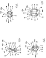
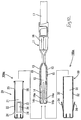
- EP
- European Patent Office
- Prior art keywords
- shell
- terminal fitting
- female terminal
- main body
- resilient contact
- Prior art date
- Legal status (The legal status is an assumption and is not a legal conclusion. Google has not performed a legal analysis and makes no representation as to the accuracy of the status listed.)
- Granted
Links
- 238000000034 method Methods 0.000 claims description 5
- 230000013011 mating Effects 0.000 claims description 2
- 239000003381 stabilizer Substances 0.000 description 10
- 239000002184 metal Substances 0.000 description 7
- 229910052751 metal Inorganic materials 0.000 description 7
- 238000003780 insertion Methods 0.000 description 5
- 230000037431 insertion Effects 0.000 description 5
- 238000005452 bending Methods 0.000 description 4
- 230000002452 interceptive effect Effects 0.000 description 2
- 230000000717 retained effect Effects 0.000 description 2
- 238000002788 crimping Methods 0.000 description 1
- 150000002739 metals Chemical class 0.000 description 1
- 230000000087 stabilizing effect Effects 0.000 description 1
Images



Classifications
-
- H—ELECTRICITY
- H01—ELECTRIC ELEMENTS
- H01R—ELECTRICALLY-CONDUCTIVE CONNECTIONS; STRUCTURAL ASSOCIATIONS OF A PLURALITY OF MUTUALLY-INSULATED ELECTRICAL CONNECTING ELEMENTS; COUPLING DEVICES; CURRENT COLLECTORS
- H01R13/00—Details of coupling devices of the kinds covered by groups H01R12/70 or H01R24/00 - H01R33/00
- H01R13/46—Bases; Cases
- H01R13/465—Identification means, e.g. labels, tags, markings
-
- H—ELECTRICITY
- H01—ELECTRIC ELEMENTS
- H01R—ELECTRICALLY-CONDUCTIVE CONNECTIONS; STRUCTURAL ASSOCIATIONS OF A PLURALITY OF MUTUALLY-INSULATED ELECTRICAL CONNECTING ELEMENTS; COUPLING DEVICES; CURRENT COLLECTORS
- H01R13/00—Details of coupling devices of the kinds covered by groups H01R12/70 or H01R24/00 - H01R33/00
- H01R13/02—Contact members
- H01R13/10—Sockets for co-operation with pins or blades
- H01R13/11—Resilient sockets
-
- H—ELECTRICITY
- H01—ELECTRIC ELEMENTS
- H01R—ELECTRICALLY-CONDUCTIVE CONNECTIONS; STRUCTURAL ASSOCIATIONS OF A PLURALITY OF MUTUALLY-INSULATED ELECTRICAL CONNECTING ELEMENTS; COUPLING DEVICES; CURRENT COLLECTORS
- H01R13/00—Details of coupling devices of the kinds covered by groups H01R12/70 or H01R24/00 - H01R33/00
- H01R13/64—Means for preventing incorrect coupling
- H01R13/642—Means for preventing incorrect coupling by position or shape of contact members
Definitions
- the present invention relates to a female terminal fitting wherein a terminal main body has a shell attached to its exterior.
- a female terminal fitting wherein a terminal main body has a shell attached to its exterior is described in US Patent No. 5,599,212.
- a shell is attached to the exterior of a terminal main body provided with an electric wire contacting member and resilient contacts, this shell covering the resilient contacts.
- one of two types of female terminal fitting can be housed within a housing: a female terminal fitting having either a tin-plated terminal main body or a gold-plated terminal main body.
- the gold-plated female terminal fittings are used in other circuits requiring a lower degree of contact reliability.
- tin-plated female terminal fittings and gold-plated terminal fittings use identical main bodies and shells. It is however somewhat difficult to visually distinguish between these identical main bodies even if they have been plated with different metals.
- the present invention has taken the above problem into consideration, and aims to make it possible to distinguish between a plurality of types of female terminal fittings.
- a female terminal fitting comprising a main body having a connection region for attachment to an electric wire, and a resilient contact for engaging a male terminal fitting, said terminal fitting further including a shell adapted to receive and cover said resilient contact, wherein said shell is one of a plurality of types of shells, each type of shell having a physical distinguishing feature.
- Such an arrangement makes it possible to distinguish visually and/or by touch between one shell and another.
- each type of shell is rectangular in section and box-like, and each type of shell may have a common mouth configuration to guide a mating connector to said terminal.
- the distinguishing feature may comprise one or more of the following features: the presence or absence of a protrusion, the presence or absence of an aperture in the wall of the shell, the orientation of a resilient latching arm, the position of an aperture with respect to a latching arm, the absence of an aperture in relation to a latching arm, different outer dimensions of the shells, in particular the width in relation to opposite resilient contacts.
- An aperture of the shell may permit movement of a resilient contact therein, thereby permitting the terminal fitting to be narrower than if a bending space for the resilient contact was provided wholly within the shell.
- the invention also provides a method of distinguishing female terminal fittings comprising a main body having a connection region for attachment to an electric wire, and a resilient contact for engaging a male terminal fitting, and a shell adapted to receive and cover said resilient contact, the method comprising the steps of providing a plurality of different types of shell, each type of shell having different physical features to permit the shell type to be distinguished.
- Female terminal fittings of the present embodiment exist in two types: a gold-plated female terminal fitting 10Au and a tin-plated female terminal fitting 10Sn. These have a terminal main body 11 which is formed from an electrically conductive metal.
- the terminal main body 11 comprises an electric wire contacting member 16 which is joined to an electric wire 17 and resilient contacts 14 which make contact with a male tab 45.
- a metal shell 20 or 30 is attached to the terminal main body 11 so as to cover the resilient contacts 14.
- the terminal main bodies 11 of the gold-plated female terminal fitting 10Au and the tin-plated female terminal fitting 10Sn are the same.
- the metal shells 20 and 30 are formed as two differing types, one for the gold-plated female terminal fitting 10Au and the other for the tin-plated female terminal fitting 10Sn, thus providing a means for distinguishing between the two.
- the gold-plated female terminal fitting 10Au can be distinguished by the first shell 20, and the tin-plated female terminal fitting 10Sn can be distinguished by the second shell 30.
- the terminal main body 11 which is formed from a metal sheet that is punched out in a specified shape and then bent, has a long and narrow shape in an anterior-posterior direction.
- a pair of supporting walls 13 rise upwards from left and right edges of a base wall 12 of an anterior portion of the terminal main body 11.
- a left and right pair of resilient contacts 14 bend inwards form the supporting walls 13.
- the resilient contacts 14 are long and narrow in an anterior-posterior direction and are formed by being cut out from the supporting walls 13.
- Posterior ends of the resilient contacts 14 join with the supporting walls 13, the anterior ends thereof extending in a cantilevered shape.
- the posterior ends of the resilient contacts 14 that join with the supporting walls 13 function as a fulcrum allowing the resilient contacts 14 to bend outwards.
- These left and right resilient contacts 14 are closest towards one another at the location of bent members 14a provided towards their anterior ends.
- the resilient contacts 14 move outwards as the male tab 45 is inserted between the bent members 14a, and the resilient returning force of the resilient contacts 14 causes these resilient contacts 14 and the male tab 45 to join with a prescribed contacting force.
- Outer faces of anterior ends 14b (which are situated to the anterior of the bent members 14a of the resilient contacts 14) are located at the same position, relative to the widthwise direction (the left-right direction), as outer faces of the supporting walls 13. Portions of the supporting walls 13 bend outwards to form contacting members 15 capable of making contact with a short circuiting terminal 42.
- the contacting members 15 protrude outwards relative to outer faces of the supporting walls 13.
- the distance to which these contacting members 15 protrude is approximately the same as the wall thickness of side walls 22 and 32 of the shells 20 and 30.
- the contacting members 15 are located towards the posterior (relative to the anterior-posterior direction) of the resilient contacts 14.
- Approximately the posterior half of the terminal main body 11 comprises the electric wire contacting member 16, which is joined by crimping to the end of the electric wire 17.
- the surface of the terminal main body 11 is gold-plated or tin-plated.
- the gold-plated terminal main body 11 is attached to the shell 20, and the tin-plated terminal main body 11 is attached to the shell 30.
- the shell 20 which is made from a metal sheet which is stamped out in a prescribed shape and then bent, is long and narrow in the anterior-posterior direction, has an angular tubular shape, and is open at its anterior and posterior end faces.
- the shell 20 comprises a base wall 21, a pair of side walls 22 that rise upwards from left and right side edges of the base wall 21, and an upper face wall 23 that extends inwards from both edges of the side walls 22 that rise upwards.
- the shell 20 When the shell 20 has been attached to the terminal main body 11, it covers the resilient contacts 14 and the supporting walls 13. Lower edges and upper edges of the supporting walls 13 make contact with the base wall 21 and the upper face wall 23, thereby preventing the shell 20 from moving up or down relative to the terminal main body 11.
- the outer faces of the supporting walls 13 make contact with inner faces of the two side walls 22, thereby preventing the shell 20 from moving right or left relative to the terminal main body 11.
- the outer faces of the anterior ends 14b of the resilient contacts 14 of the terminal main body 11 are located at the same position, relative to the left-right direction, as the inner faces of the two side walls 22.
- a pair of square holes 24 are formed in the side walls 22.
- the holes 24 have several functions; they allow the bent members 14a and the anterior ends 14b of the resilient contacts 14 to be exposed; they prevent the bent members 14a and the anterior ends 14b, which move outwards when the resilient members 14 and the male tab 45 are fitted together, from interfering with the side walls 22; and, by allowing the bent members 14a and the anterior ends 14b which are moved outwards so as to move into the recessed holes 24, they function as a bending space for the bent members 14a.
- the holes 24 are one of the distinguishing means of the present invention.
- Square window holes 25 are formed in the side walls 22 at locations to the posterior of the recessed holes 24.
- the contacting members 15 When the shell 20 is in an attached state with the terminal main body 11, the contacting members 15 are exposed to outer faces of the shell 20 via these window holes 25.
- the window holes 25 have several functions; they allow the contacting members 15 to be exposed; the contacting members 15 that protrude from the supporting walls 13 are inserted into these window holes 25; and outer faces of the contacting members 15 form a unified face with outer faces of the side walls 22.
- These window holes 25 are one of the distinguishing means of the present embodiment.
- An upper and lower symmetrical pair of lances 26 are formed at anterior ends of the base wall 21 and the upper face wall 23.
- Each lance 26 has a cantilevered shape. An anterior end thereof joins the base wall 21 or the upper face wall 23, and the lance 26 extends, in an inclined manner, outwards and towards the posterior.
- Each lance 26 is capable of resiliently bending inwards, the anterior end thereof serving as the fulcrum.
- the lances 26 are located to the anterior (in the anterior-posterior direction) relative to the window holes 25. That is, the lances 26 are located further inwards relative to the direction of insertion of the gold-plated female terminal fitting 10Au into the cavity 41Au.
- These lances 26 are provided on the base wall 21 and the upper face wall 23, whereas the window holes 25 are provided in the side walls 22. That is, the lances 26 and the window holes 25 are provided at locations which, when viewed from the direction of insertion, are mutually separated by 90 degrees. Consequently, when the gold-plated female terminal fitting 10Au is inserted into the cavity 41Au, the lances 26 and the window holes 25 each have separate paths of movement.
- the lances 26 are one of the distinguishing means of the present embodiment.
- Stabilizers 27 are provided on the shell 20. These stabilizers 27 are formed on upper and lower edges of the side walls 22, form a unified face therewith, and extend upwards and downwards, respectively. When the gold-plated female terminal fitting 10Au is inserted into the cavity 41Au, these stabilizers 27 fit into guiding grooves 43 formed in the inner walls of the cavity 41Au, thereby stabilizing the position of the gold-plated female terminal fitting 10Au. These stabilizers 27 are located at an approximately central position (relative to the anterior-posterior direction) between the holes 24 and the window holes 25.
- the shell 30 will be described and compared to the shell 20.
- the shell 30 is made from a metal sheet which is stamped out in a prescribed shape and then bent, is long and narrow in the anterior-posterior direction, has an angular tubular shape, and is open at its anterior and posterior end faces.
- the shell 30 comprises a base wall 31, a pair of side walls 32 that rise upwards from left and right side edges of the base wall 31, and an upper face wall 33 that extends inwards from both edges of the side walls 32 that rise upwards.
- Lower edges and upper edges of the supporting walls 13 make contact with the base wall 31 and the upper face wall 33, thereby preventing the shell 30 from moving up or down relative to the terminal main body 11.
- the outer faces of the contacting members 15 make contact with inner faces of the two side walls 32, thereby preventing the shell 30 from moving right or left relative to the terminal main body 11.
- the outer faces of the anterior ends 14b of the resilient contacts 14 of the terminal main body 11 are located inwards, relative to the left-right direction, from the inner faces of the two side walls 32.
- the shell 20 described above has a pair of square holes 24 that are formed in the side walls 22 thereof.
- the bent members 14a and the anterior ends 14b of the resilient contacts 14 are exposed at the outer faces of the shell 20 via these holes 24.
- the anterior ends of the side walls 32 of the shell 30 are not provided with openings corresponding to the holes 24. Instead, they are provided with a left and right pair of lances 34.
- These lances 34 are formed at the anterior ends of the side walls 32, join therewith and have a cantilevered shape whereby they extend in an inclined manner outwards and towards the posterior.
- the lances 34 are capable of resiliently bending inwards, the anterior ends thereof serving as the fulcrum.
- the lances 34 are retained by retaining members 44Sn formed on inner walls of the cavity 41Sn, thereby maintaining the tin-plated female terminal fitting 10Sn in a correctly inserted position.
- the lances 26 of the shell 20 are formed on the base wall 21 and the upper face wall 23.
- the lances 34 are formed on the side walls 32 of the shell 30. That is, the lances 26 and 34 are formed at mutually differing locations on the shell 20 and the shell 30 respectively.
- the lances 34 of the shell 30 are one of the distinguishing means of the present embodiment.
- the square window holes 25 are formed in the posterior portions of the side walls 22 of the shell 20, the contacting members 15 being exposed at outer faces of the shell 20 via these window holes 25.
- the side walls 32 of the shell 30 are not provided with openings corresponding to these window holes 25. Instead, the contacting members 15 remain covered by the side walls 32.
- the shell 20 is provided with the stabilizers 27.
- the shell 30 is not provided with protrusions corresponding to these stabilizers 27.
- the side walls 22 of the shell 20 make contact with the outer faces of the supporting walls 13.
- the side walls 32 of the shell 30 make contact with the outer faces of the outwardly-protruding contacting members 15.
- the space between the side walls 32 of the shell 30 is greater than the space between the side walls 22 of the shell 20.
- the width of the shell 30 is greater than the width of the shell 20.
- the cavity 41Au and the cavity 41Sn are formed within this housing 40.
- the short circuiting terminal 42 is provided in the vicinity of the cavity 41Au (see Figure 1).
- the horizontal cross-sectional shape (that is, at a right-angle to the direction of insertion) of the opening portion of the cavity 41Au has a width and height such that the shell 20 can enter therein with a suitable clearance but without moving too much.
- this opening portion is provided with guiding grooves 43 that correspond to the stabilizers 27.
- the retaining members 44Au corresponding to the lances 26 (these being formed at the upper and lower face sides) are formed inwards relative to the opening portion (see Figure 4).
- the horizontal cross-sectional shape of the opening portion to the cavity 41Sn has a width and height such that the shell 30 can enter therein with a suitable clearance but without moving too much.
- the heights of the cavities 41Au and 41Sn for the gold-plated and tin-plated female terminal fitting respectively are identical.
- the cavity 41Au is narrower than the cavity 41Sn. Consequently, the tin-plated female terminal fitting 10Sn cannot be inserted into the cavity 41Au (see Figure 9).
- the cavity 41Sn is not provided with guiding grooves 43. Consequently, the gold-plated female terminal fitting 10Au, which is provided with the stabilizers 27, cannot be inserted into the cavity 41Sn (see Figure 5).
- the retaining members 44Sn which correspond to the lances 34, are formed in the left and right side walls, at locations inwards from the opening portion, of the cavity 41Sn (see Figure 8).
- the gold-plated female terminal fitting 10Au and the tin-plated female terminal fitting 10Sn both use the same terminal main body 11, the shells 20 and 30, which are used respectively for the gold-plated and tin-plated terminal fittings, are provided with distinguishing means. These distinguishing means allow the gold-plated female terminal fitting 10Au and the tin-plated female terminal fitting 10Sn to be distinguished from one another. The distinguishing method thereof is described below.
- the shell 20 has the window holes 25 formed therein, the contacting members 15 of the terminal main body 11 being exposed at outer faces of the shell 20 via these window holes 25.
- the shell 30 is not provided with openings corresponding to the window holes 25. Consequently, the presence or absence of the window holes 25 (or, in other words, the ability to see the contacting members 15) allows one to distinguish between the gold-plated female terminal fitting and the tin-plated female terminal fitting.
- the shell 20, which is provided with the window holes 25, has the lances 26 formed thereon at locations inwards relative to the direction of insertion of the shell 20 into the cavity 41Au.
- the position of these lances 26 is such that their paths of movement, when the shell 20 is inserted into the cavity 41Au, are separate from the paths of movement of the window holes 25 (this corresponding to the location of the short circuiting terminal 42 that makes contact with the contacting members 15 exposed from these window holes 25). Consequently, the lances 26 do not interfere with the short circuiting terminal 42 when this insertion takes place.
- the shell 20 is provided with the holes 24 which prevent the bent members 14a and the anterior ends 14b of the resilient contacts 14 from interfering with the side walls 22.
- the shell 30 is not provided with openings corresponding to these recessed holes 24. The presence or absence of these holes 24 (or, in other words, the ability to see the bent members 14a and the anterior ends 14b within the holes 24) allows one to distinguish between the gold-plated female terminal fitting and the tin-plated female terminal fitting.
- the shell 20 and the shell 30 are provided with the lances 26 and 34, respectively.
- the lances 26 and 34 engage therewith.
- the lances 26 of the shell 20 are provided on the upper and lower face sides.
- the lances 34 of the shell 30 are provided on the left and right sides. Consequently, the differing positions of the lances 26 and 34 allow one to distinguish between the gold-plated female terminal fitting and the tin-plated female terminal fitting.
- the contacting members 15 enter the window holes 25 of the shell 20, these contacting members 15 are located within the wall thickness of the side walls 22. Consequently, the space between the side walls 22 of the shell 20 is less than in the case of the shell 30, which does not have window holes 25 and in which the contacting members 15 are located inwards relative to the side walls 32. As a result, the shell 20 is narrower in width than the shell 30, this difference in width allowing one to distinguish between the gold-plated female terminal fitting and the tin-plated female terminal fitting.
- the side walls 22 of the shell 20 are closer together than in the case of the shell 30. Consequently, these side walls 22 are comparatively closer to the resilient contacts 14. However, since the holes 24 are formed in these side walls 22, the side walls 22 do not interfere with the resilient contacts 14.
- the side walls 32 of the shell 30 are not provided with window holes 25. However, the shell 30 is wider than the shell 20. Consequently, a greater space is provided between the side walls 32 and the resilient contacts 14, and the side walls 32 do not interfere with the resilient contacts 14.
- the cavity 41Au and the cavity 41Sn differ in width, horizontal cross-sectional shape, in the location of the retaining members 44Au and 44Sn, and in the presence or absence of the guiding grooves 43. Consequently, if one attempts to insert into the cavity 41Sn the gold-plated female terminal fitting 10Au, which is provided with the stabilizers 27, these stabilizers 27 strike against the opening edge of the cavity 41Sn, and the gold-plated female terminal fitting 10Au cannot be inserted (see Figure 5). Conversely, if one attempts to insert the tin-plated female terminal fitting 10Sn into the cavity 41Au, the shell 30 is wider than the cavity 41Au, and cannot be inserted therein. That is, the ability or inability to insert the gold-plated female terminal fitting or the tin-plated female terminal fitting into the cavities 41Au and 41Sn allow one to distinguish between the two female terminal fittings.
Landscapes
- Details Of Connecting Devices For Male And Female Coupling (AREA)
- Connector Housings Or Holding Contact Members (AREA)
Applications Claiming Priority (2)
| Application Number | Priority Date | Filing Date | Title |
|---|---|---|---|
| JP2000174002A JP3719107B2 (ja) | 2000-06-09 | 2000-06-09 | 雌端子金具 |
| JP2000174002 | 2000-06-09 |
Publications (3)
| Publication Number | Publication Date |
|---|---|
| EP1162697A2 true EP1162697A2 (de) | 2001-12-12 |
| EP1162697A3 EP1162697A3 (de) | 2002-05-29 |
| EP1162697B1 EP1162697B1 (de) | 2009-06-10 |
Family
ID=18676127
Family Applications (1)
| Application Number | Title | Priority Date | Filing Date |
|---|---|---|---|
| EP01303613A Expired - Lifetime EP1162697B1 (de) | 2000-06-09 | 2001-04-20 | Kontaktbuchsenarmatur |
Country Status (4)
| Country | Link |
|---|---|
| US (1) | US6565396B2 (de) |
| EP (1) | EP1162697B1 (de) |
| JP (1) | JP3719107B2 (de) |
| DE (1) | DE60138940D1 (de) |
Families Citing this family (25)
| Publication number | Priority date | Publication date | Assignee | Title |
|---|---|---|---|---|
| FR2853997B1 (fr) * | 2003-04-15 | 2009-07-03 | Guy Coulon | Piece de contact pour connecteur electrique |
| US6997750B2 (en) * | 2003-07-23 | 2006-02-14 | Fci Americas Technology, Inc. | Electrical connector contact |
| US20050059303A1 (en) * | 2003-08-27 | 2005-03-17 | Panella Augusto P. | Dual plane power contact |
| US7261604B2 (en) * | 2003-12-22 | 2007-08-28 | Delphi Technologies, Inc. | Electrical terminal element |
| JP3976008B2 (ja) * | 2004-01-07 | 2007-09-12 | 住友電装株式会社 | 端子金具 |
| JP5041904B2 (ja) * | 2007-08-03 | 2012-10-03 | Smk株式会社 | コネクタ及びコネクタ端子構造 |
| KR101598633B1 (ko) * | 2009-11-11 | 2016-02-29 | 타이코에이엠피 주식회사 | 커넥터용 단자 |
| JP5734003B2 (ja) | 2011-02-04 | 2015-06-10 | 矢崎総業株式会社 | 端子 |
| US8449326B2 (en) * | 2011-05-18 | 2013-05-28 | Holland Electronics, Llc | Coaxial connector jack with multipurpose cap |
| JP2013016359A (ja) | 2011-07-04 | 2013-01-24 | Sumitomo Wiring Syst Ltd | 端子金具 |
| DE102012017949A1 (de) * | 2011-09-28 | 2013-03-28 | Sumitomo Wiring Systems, Ltd. | Anschlusspassstück |
| EP4024617A1 (de) | 2014-04-24 | 2022-07-06 | Molex, LLC | Anschlussstück |
| JP2016091970A (ja) * | 2014-11-11 | 2016-05-23 | Smk株式会社 | ソケット端子構造 |
| US9905953B1 (en) | 2016-09-30 | 2018-02-27 | Slobodan Pavlovic | High power spring-actuated electrical connector |
| JP7011253B2 (ja) * | 2018-01-26 | 2022-01-26 | タツタ電線株式会社 | コネクタ端子、及びコネクタ |
| CN111937250B (zh) | 2018-02-26 | 2022-09-30 | 皇家精密制品有限责任公司 | 用于高功率应用的弹簧致动式电连接器 |
| WO2019237009A1 (en) | 2018-06-07 | 2019-12-12 | Royal Precision Products, Llc | Electrical connector system with internal spring component |
| WO2020150399A1 (en) | 2019-01-15 | 2020-07-23 | Royal Precision Products, Llc | Shielded electrical connector system with internal spring component |
| DE112020000459T5 (de) | 2019-01-21 | 2021-11-25 | Royal Precision Products, Llc | Stromverteilungsanordnung mit schraubenlosem sammelschienensystem |
| EP3783751A1 (de) * | 2019-08-20 | 2021-02-24 | Aptiv Technologies Limited | Verbinder für automobilanwendungen |
| US11721942B2 (en) | 2019-09-09 | 2023-08-08 | Eaton Intelligent Power Limited | Connector system for a component in a power management system in a motor vehicle |
| CN114787815A (zh) | 2019-09-09 | 2022-07-22 | 伊顿智能动力有限公司 | 具有可读和可记录标记的连接器记录系统 |
| JP7361550B2 (ja) | 2019-09-20 | 2023-10-16 | タイコエレクトロニクスジャパン合同会社 | コネクタ |
| JP7314012B2 (ja) * | 2019-10-07 | 2023-07-25 | 日本航空電子工業株式会社 | ソケットコンタクト及びコネクタ |
| DE112021003695T5 (de) | 2020-07-29 | 2023-06-29 | Eaton Intelligent Power Limited | Verbindersystem einschliesslich eines verriegelungssystems |
Citations (3)
| Publication number | Priority date | Publication date | Assignee | Title |
|---|---|---|---|---|
| EP0223586A2 (de) | 1985-11-19 | 1987-05-27 | RAYCHEM CORPORATION (a California corporation) | Elektrische Verbinder mit Mehrzweck-Kontakthohlräumen |
| DE4342820A1 (de) | 1992-12-21 | 1994-06-23 | Whitaker Corp | Zweiteiliger elektrischer Verbinder mit Kurzschließmöglichkeit und Kurzschließfeder für diesen |
| US5599212A (en) | 1993-05-17 | 1997-02-04 | Yazaki Corporation | Socket terminal |
Family Cites Families (7)
| Publication number | Priority date | Publication date | Assignee | Title |
|---|---|---|---|---|
| GB8728575D0 (en) * | 1987-12-07 | 1988-01-13 | Amp Gmbh | Electrical socket terminal |
| JPH0635402Y2 (ja) * | 1989-03-08 | 1994-09-14 | 日本航空電子工業株式会社 | 誤接続防止構造を有するコネクタ |
| FR2758214B1 (fr) * | 1997-01-08 | 1999-01-29 | Cinch Connecteurs Sa | Organe de contact electrique femelle |
| KR19980074670A (ko) * | 1997-03-26 | 1998-11-05 | 윤종용 | 단자접속구조 |
| DE19747115A1 (de) * | 1997-10-24 | 1999-04-29 | Amp Gmbh | Elektrische Steckverbinderanordnung und elektrischer Kontakt |
| DE19841216C2 (de) * | 1998-09-09 | 2001-02-15 | Framatome Connectors Int | Buchsenstecker für elektrische Verbinder mit Kodierrippe |
| JP2001057265A (ja) * | 1999-08-18 | 2001-02-27 | Sumitomo Wiring Syst Ltd | 端子金具 |
-
2000
- 2000-06-09 JP JP2000174002A patent/JP3719107B2/ja not_active Expired - Fee Related
-
2001
- 2001-04-20 EP EP01303613A patent/EP1162697B1/de not_active Expired - Lifetime
- 2001-04-20 DE DE60138940T patent/DE60138940D1/de not_active Expired - Lifetime
- 2001-06-01 US US09/870,747 patent/US6565396B2/en not_active Expired - Fee Related
Patent Citations (3)
| Publication number | Priority date | Publication date | Assignee | Title |
|---|---|---|---|---|
| EP0223586A2 (de) | 1985-11-19 | 1987-05-27 | RAYCHEM CORPORATION (a California corporation) | Elektrische Verbinder mit Mehrzweck-Kontakthohlräumen |
| DE4342820A1 (de) | 1992-12-21 | 1994-06-23 | Whitaker Corp | Zweiteiliger elektrischer Verbinder mit Kurzschließmöglichkeit und Kurzschließfeder für diesen |
| US5599212A (en) | 1993-05-17 | 1997-02-04 | Yazaki Corporation | Socket terminal |
Also Published As
| Publication number | Publication date |
|---|---|
| US6565396B2 (en) | 2003-05-20 |
| EP1162697A3 (de) | 2002-05-29 |
| JP3719107B2 (ja) | 2005-11-24 |
| DE60138940D1 (de) | 2009-07-23 |
| US20010051471A1 (en) | 2001-12-13 |
| JP2001351739A (ja) | 2001-12-21 |
| EP1162697B1 (de) | 2009-06-10 |
Similar Documents
| Publication | Publication Date | Title |
|---|---|---|
| US6565396B2 (en) | Female terminal fitting | |
| EP1193808B1 (de) | Elektrischer Verbinder | |
| JP3320378B2 (ja) | 電気コネクタ | |
| EP1162698B1 (de) | Kontaktbüchsenarmatur | |
| US7645165B2 (en) | Electrical connector with improved shielding shell | |
| US4571017A (en) | Electrical connector assembly | |
| EP1124290A2 (de) | Elektrischer Verbinder | |
| EP1113532B1 (de) | Weiblicher Kontakt für einen elektrischen Steckverbinder | |
| EP2082457B1 (de) | Elektrischer verbinder mit scoop-proof-dom | |
| EP0993080A2 (de) | Koaxiale Schaltverbindungsanordnung | |
| EP1115181A1 (de) | Elektrischer Verbinder | |
| EP1786066B1 (de) | Verbinder | |
| EP0905823A1 (de) | Elektrischer Verbinder | |
| US11088483B2 (en) | Terminal metal fitting with spring contact and spring contact deformation restriction portion | |
| EP1557908B1 (de) | Ein verbinder | |
| EP1244180B1 (de) | Elektrischer Verbinder für Flachkabel und Herstellungsverfahren | |
| JP3106282B2 (ja) | コネクタ | |
| US6336820B2 (en) | Switch-equipped coaxial connector | |
| EP1168518A2 (de) | Verbinder | |
| US6648685B2 (en) | Connector | |
| US11626683B2 (en) | Connector with retainer | |
| CN223828828U (zh) | 可锁定的连接器总成及可锁定的连接器 | |
| EP1199773B1 (de) | Elektrischer Verbinder und Klemme | |
| JP2002298983A (ja) | コネクタ | |
| KR102954731B1 (ko) | 전자 부품용 커넥터 조립체 |
Legal Events
| Date | Code | Title | Description |
|---|---|---|---|
| PUAI | Public reference made under article 153(3) epc to a published international application that has entered the european phase |
Free format text: ORIGINAL CODE: 0009012 |
|
| 17P | Request for examination filed |
Effective date: 20010511 |
|
| AK | Designated contracting states |
Kind code of ref document: A2 Designated state(s): AT BE CH CY DE DK ES FI FR GB GR IE IT LI LU MC NL PT SE TR |
|
| AX | Request for extension of the european patent |
Free format text: AL;LT;LV;MK;RO;SI |
|
| PUAL | Search report despatched |
Free format text: ORIGINAL CODE: 0009013 |
|
| AK | Designated contracting states |
Kind code of ref document: A3 Designated state(s): AT BE CH CY DE DK ES FI FR GB GR IE IT LI LU MC NL PT SE TR |
|
| AX | Request for extension of the european patent |
Free format text: AL;LT;LV;MK;RO;SI |
|
| RIC1 | Information provided on ipc code assigned before grant |
Free format text: 7H 01R 13/115 A, 7H 01R 13/642 B |
|
| AKX | Designation fees paid |
Designated state(s): DE FR GB IT |
|
| 17Q | First examination report despatched |
Effective date: 20040114 |
|
| GRAP | Despatch of communication of intention to grant a patent |
Free format text: ORIGINAL CODE: EPIDOSNIGR1 |
|
| RIC1 | Information provided on ipc code assigned before grant |
Ipc: H01R 13/642 20060101ALI20081020BHEP Ipc: H01R 13/11 20060101AFI20081020BHEP |
|
| GRAS | Grant fee paid |
Free format text: ORIGINAL CODE: EPIDOSNIGR3 |
|
| GRAA | (expected) grant |
Free format text: ORIGINAL CODE: 0009210 |
|
| AK | Designated contracting states |
Kind code of ref document: B1 Designated state(s): DE FR GB IT |
|
| REG | Reference to a national code |
Ref country code: GB Ref legal event code: FG4D |
|
| REF | Corresponds to: |
Ref document number: 60138940 Country of ref document: DE Date of ref document: 20090723 Kind code of ref document: P |
|
| PLBE | No opposition filed within time limit |
Free format text: ORIGINAL CODE: 0009261 |
|
| STAA | Information on the status of an ep patent application or granted ep patent |
Free format text: STATUS: NO OPPOSITION FILED WITHIN TIME LIMIT |
|
| 26N | No opposition filed |
Effective date: 20100311 |
|
| PGFP | Annual fee paid to national office [announced via postgrant information from national office to epo] |
Ref country code: IT Payment date: 20120315 Year of fee payment: 12 |
|
| PGFP | Annual fee paid to national office [announced via postgrant information from national office to epo] |
Ref country code: GB Payment date: 20130417 Year of fee payment: 13 Ref country code: DE Payment date: 20130508 Year of fee payment: 13 |
|
| PGFP | Annual fee paid to national office [announced via postgrant information from national office to epo] |
Ref country code: FR Payment date: 20130625 Year of fee payment: 13 |
|
| REG | Reference to a national code |
Ref country code: DE Ref legal event code: R119 Ref document number: 60138940 Country of ref document: DE |
|
| GBPC | Gb: european patent ceased through non-payment of renewal fee |
Effective date: 20140420 |
|
| REG | Reference to a national code |
Ref country code: FR Ref legal event code: ST Effective date: 20141231 |
|
| PG25 | Lapsed in a contracting state [announced via postgrant information from national office to epo] |
Ref country code: DE Free format text: LAPSE BECAUSE OF NON-PAYMENT OF DUE FEES Effective date: 20141101 Ref country code: GB Free format text: LAPSE BECAUSE OF NON-PAYMENT OF DUE FEES Effective date: 20140420 |
|
| REG | Reference to a national code |
Ref country code: DE Ref legal event code: R119 Ref document number: 60138940 Country of ref document: DE Effective date: 20141101 |
|
| PG25 | Lapsed in a contracting state [announced via postgrant information from national office to epo] |
Ref country code: FR Free format text: LAPSE BECAUSE OF NON-PAYMENT OF DUE FEES Effective date: 20140430 |
|
| PG25 | Lapsed in a contracting state [announced via postgrant information from national office to epo] |
Ref country code: IT Free format text: LAPSE BECAUSE OF NON-PAYMENT OF DUE FEES Effective date: 20140420 |