EP1162716A2 - Elektromotor, insbesondere Lüftermotor - Google Patents
Elektromotor, insbesondere Lüftermotor Download PDFInfo
- Publication number
- EP1162716A2 EP1162716A2 EP01113134A EP01113134A EP1162716A2 EP 1162716 A2 EP1162716 A2 EP 1162716A2 EP 01113134 A EP01113134 A EP 01113134A EP 01113134 A EP01113134 A EP 01113134A EP 1162716 A2 EP1162716 A2 EP 1162716A2
- Authority
- EP
- European Patent Office
- Prior art keywords
- electric motor
- rotor
- motor according
- stator
- rotor shaft
- Prior art date
- Legal status (The legal status is an assumption and is not a legal conclusion. Google has not performed a legal analysis and makes no representation as to the accuracy of the status listed.)
- Withdrawn
Links
Images

Classifications
-
- H—ELECTRICITY
- H02—GENERATION; CONVERSION OR DISTRIBUTION OF ELECTRIC POWER
- H02K—DYNAMO-ELECTRIC MACHINES
- H02K7/00—Arrangements for handling mechanical energy structurally associated with dynamo-electric machines, e.g. structural association with mechanical driving motors or auxiliary dynamo-electric machines
- H02K7/08—Structural association with bearings
- H02K7/083—Structural association with bearings radially supporting the rotary shaft at both ends of the rotor
-
- H—ELECTRICITY
- H02—GENERATION; CONVERSION OR DISTRIBUTION OF ELECTRIC POWER
- H02K—DYNAMO-ELECTRIC MACHINES
- H02K5/00—Casings; Enclosures; Supports
- H02K5/04—Casings or enclosures characterised by the shape, form or construction thereof
- H02K5/16—Means for supporting bearings, e.g. insulating supports or means for fitting bearings in the bearing-shields
- H02K5/167—Means for supporting bearings, e.g. insulating supports or means for fitting bearings in the bearing-shields using sliding-contact or spherical cap bearings
- H02K5/1672—Means for supporting bearings, e.g. insulating supports or means for fitting bearings in the bearing-shields using sliding-contact or spherical cap bearings radially supporting the rotary shaft at both ends of the rotor
-
- H—ELECTRICITY
- H02—GENERATION; CONVERSION OR DISTRIBUTION OF ELECTRIC POWER
- H02K—DYNAMO-ELECTRIC MACHINES
- H02K9/00—Arrangements for cooling or ventilating
- H02K9/02—Arrangements for cooling or ventilating by ambient air flowing through the machine
- H02K9/04—Arrangements for cooling or ventilating by ambient air flowing through the machine having means for generating a flow of cooling medium
- H02K9/06—Arrangements for cooling or ventilating by ambient air flowing through the machine having means for generating a flow of cooling medium with fans or impellers driven by the machine shaft
Definitions
- the invention relates to an electric motor with a stator and Rotor, the rotor at least one permanent magnet and one Has rotor shaft and is mounted radially and axially and wherein the stator has at least two coils when energized with alternating currents generate a rotating magnetic field through which the rotor can be driven, in particular for use as a fan blower.
- Such motors and their rotor are known from the prior art axially by axially supporting the rotor shaft in a sintered bearing is realized.
- the disadvantage of these engines is that by a excessive wear between the sintered bearing and the rotor shaft first a strong noise emission is caused and then it closes there is a total failure of the engine.
- the object of the invention is therefore to specify an engine that has a long service life and at the same time has low noise emissions.
- the rotor is axially supported by an elastic thrust washer, the elastic Thrust washer is arranged axially on one side of the rotor.
- this axial bearing is a permanent axial bearing realized.
- the motor can be used regardless of the position if a second elastic Thrust washer is arranged axially on the other side of the rotor. So Depending on its current position, the rotor can always be the first or second Thrust washer or alternately the first and second thrust washers strain. Furthermore, due to the elasticity of the thrust washers Impact noise is prevented because the load changes when the Thrust washers the elastic thrust washers striking the Cushion the rotor in a springy manner
- Elastic thrust washers which consist of a rubber-like plastic matrix consist of microfibers on one side are upset. These thrust washers are particularly durable because the microfibers do not separate from the plastic matrix. If the Microfibers are stochastically distributed on the plastic matrix, also results from continuous rotation of the motor in one direction no comb effect.
- a low-viscosity lubricant is particularly preferred here, since a particularly low frictional resistance of the thrust washers is achieved.
- a capillary gap to hold lubricants sucks in lubricants, which are pressed out during operation and / or assembly on.
- the thrust washer can Take up lubricant again due to capillary action.
- a particularly simple radial bearing can be realized that the rotor shaft is polished in the area of the radial bearing points.
- the rotor is particularly easy to manufacture if the permanent magnet is embedded in plastic.
- the motor can be made particularly compact if the stator as Coil is designed with coils attached to it and the Rotor is arranged within the winding body.
- the aforementioned design is particularly easy to implement, if two crossing coils are attached to the winding body.
- the prescribed Motor particularly good as a fan motor with one placed on the rotor shaft Operate the fan wheel.
- An elastic thrust washer 1 has a rubber-like plastic matrix 2, for example made of soft PVC, on one side of which microfibers 3, for example. are made of nylon cut flock, which are preferably stochastic are distributed. This also results from continuous painting in no comb effect in one direction. The fibers straighten up again and again and form small capillaries, which are particularly suitable, liquids to record. It is also possible to make a simple one, possibly to one side closed felt disc if the requirements are not are too high.
- a rotor 4 has a rotationally symmetrical ring-shaped Permanent magnet 5, which has a magnetic carrier 6 made of plastic is connected to a rotor shaft 7.
- the magnetic carrier 6 has on its a thrust surface 6a at an axial end. On its other axial At the end, the magnetic carrier 6 has a lowering 8 for at least part of it Inclusion of an elastic thrust washer 1 with a thrust surface 8a on.
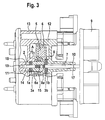
- the rotor 4 from Figure 2 is provided with a fan wheel 9 and radially in bearing areas 10, 11 designed as a winding body Stator, which consists of an upper winding part 12 and a lower winding part 13 exists, stored.
- the rotor 4 is axially floating over two Thrust washers 1a, 1b in the depression 8 in the rotor 4 and a recess 14 stored in the lower body 13.
- the permanent magnet 5 embedded in the magnet carrier 6 is on the Pressed rotor shaft 7.
- a roughening 15 is attached to increase the tight fit.
- the Rotor shaft 7 is in areas of radial bearing 17, 18 in the winding body 12, 13 polished to reduce friction.
- the thrust washers 1a, 1b are in the depression 8 of the rotor 4 or in the recess 14 of the lower winding body 13 arranged so that the sides with the microfibers 3a, 3b on the magnet carrier 6 of the rotor 4 trained contact surfaces 6a, 8a are facing.
- the relative movement takes place between the fiber side 3a, 3b of the thrust washer 1a, 1b and the rotor 4 with the contact surfaces 6a, 6b instead.
- the thrust washers 1a, 1b are in the event of a load compared to that as a winding body 12, 13 trained stator firmly. This is achieved through a higher coefficient of friction the rubber-like plastic matrix 2 opposite the stator than the microfibers 3 with respect to the rotor 4.
- Low-viscosity lubricant is in the fibers of the thrust washers 1a, 1b brought in.
- the rotor 4 can also consist entirely of magnetic material.
- a capillary gap 19 can be seen in FIG can, which is pressed out of the thrust washer 1a.
- the motor can be installed in any position, so that depending on the application axial contact force via the thrust washer 1a or 1b into the contact surface 6a or 8a is passed.
- both Thrust washers 1a, 1b alternately loaded
- the lubricant squeezed out by the compression can in the Kick capillary gap 19. After pressing on, the thrust washer relaxes 1a and the lubricant located in the capillary gap 19 sucked back into the fibers 3a of the thrust washer 1a.
- the bearing is protected against loss of lubricant on the one hand by the capillary action of the fibers 3b described above and secondly by the arrangement of the thrust washer 1b in the Lowering 8 in the rotor 4. This may collect through rotation Leaking lubricant in the corner contour of the lowering 8 and can when stopped by capillary action back into the fibers 3b of the thrust washer 1b hike back.
Landscapes
- Engineering & Computer Science (AREA)
- Power Engineering (AREA)
- Connection Of Motors, Electrical Generators, Mechanical Devices, And The Like (AREA)
- Motor Or Generator Frames (AREA)
- Sliding-Contact Bearings (AREA)
- Permanent Magnet Type Synchronous Machine (AREA)
- Permanent Field Magnets Of Synchronous Machinery (AREA)
Abstract
Description
- Figur 1
- einen Schnitt durch eine besonders bevorzugte Anlaufscheibe
- Figur 2
- einen Teilschnitt durch einen besonders bevorzugten Rotor
- Figur 3
- eine Ansicht und einen Teilschnitt eines besonders bevorzugten Motors mit ausgesetzten Lüfterrad mit einem Rotor aus Figur 2 und Anlaufscheiben aus Figur 1.
- Figur 4
- den Teilschnitt A aus Figur 3
Claims (21)
- Elektromotor mit einem Stator und einem Rotor, wobei der Rotor mindestens einen Permanentmagneten und eine Rotorwelle aufweist und der Stator mindestens zwei Spulen aufweist, die Bestromung mit Wechselströmen ein sich drehendes Magnetfeld erzeugen, durch den Rotor antreibbar ist und die Rotorwelle radial und axial gelagert ist, dadurch gekennzeichnet, daß der Rotor (4) durch mindestens eine elastische Anlaufscheibe (1a,1b) gelagert ist, wobei eine Anlaufscheibe (1a) axial auf einer Seite des Rotors (4) angeordnet ist.
- Elektromotor nach Anspruch 1, dadurch gekennzeichnet, daß eine zweite Anlaufscheibe (1b) auf der anderen Seite des Rotors (4)angeordnet ist und der Rotor (4)je nach seiner Lage ständig die erste oder zweite elastische Anlaufscheibe (1a, 1b) oder abwechselnd die erste und zweite Anlaufscheibe (1a, 1b) belastet.
- Elektromotor nach einem der vorstehenden Ansprüche, dadurch gekennzeichnet, daß die Anlaufscheiben (1, 1a, 1b) aus einer gummiartigen Kunststoffmatrix (2)bestehen, auf der auf einer Seite Mikrofasern (3, 3a, 3b)aufgebracht sind. Elektromotor nach einem der vorstehenden Ansprüche, dadurch gekennzeichnet, daß das Schmiermittel in den Anlaufscheiben (1, 1a, 1b) niederviskos ist.
- Elektromotor nach Anspruch 3, dadurch gekennzeichnet, daß die Seite mit den Mikrofasern (3, 3a, 3b) jeweils dem Rotor (4) zugewandt ist.
- Elektromotor nach Anspruch 3 oder 4, dadurch gekennzeichnet, daß die Mikrofasern (3, 3a, 3b) stochastisch verteilt sind.
- Elektromotor nach einem der vorstehenden Ansprüche, dadurch gekennzeichnet, daß Schmiermittel in den Anlaufscheiben (1, 1a, 1b) vorhanden ist
- Elektromotor nach Anspruch 6, dadurch gekennzeichnet, daß das Schmiermittel in den Anlaufscheiben (1, 1a, 1b) niederviskos ist.
- Elektromotor nach einem der vorstehenden Ansprüche, dadurch gekennzeichnet, daß mindestens eine Anlaufscheibe (1a) in einer Ausnehmung (14) des Stators angeordnet ist, die zur Aufnahme der Lagerscheibe (1a) ausgebildet ist.
- Elektromotor nach einem der vorstehenden Ansprüche, dadurch gekennzeichnet, daß der Rotor (4) mindestens eine Absenkung (8) zur Aufnahme der zweiten Anlaufscheibe (1b) aufweist.
- Elektromotor nach Anspruch 8 oder 9, dadurch gekennzeichnet, daß die Ausnehmungen (14) bzw. Absenkungen (8) des Stators bzw. des Rotors (4) kegelstumpfförmig ausgebildet sind.
- Elektromotor nach einem der vorstehenden Ansprüche, dadurch gekennzeichnet, daß der Stator (12, 13) einen axialen Anschlag (20) aufweist, mit dem die axiale Bewegung der Rotorwelle (7) bei der Montage von zusätzlichen Bauteilen auf der Rotorwelle (7) begrenzbar ist.
- Elektromotor nach einem der vorstehenden Ansprüche, dadurch gekennzeichnet, daß zwischen dem Rotor (4) und dem Stator (12, 13) ein Kapillarspalt (19) zur Aufnahme von Schmiermittel vorgesehen ist.
- Elektromotor nach einem der vorstehenden Ansprüche, dadurch gekennzeichnet, daß die Rotorwelle (7) im radialen Lagerbereich (10, 11) poliert ist.
- Elektromotor nach einem der vorstehenden Ansprüche, dadurch gekennzeichnet, daß der Rotor (4) einen in einen Magnetträger (6) gebetteten Permanentmagneten (5) aufweist.
- Elektromotor nach Anspruch 1 bis 13, dadurch gekennzeichnet, daß er einen rotationssymetrischen Magneten aufweist, der starr mit der Rotorwelle (7) verbunden ist.
- Elektromotor nach einem der vorstehenden Ansprüche, dadurch gekennzeichnet, daß der Stator als Wickelkörper (12, 13) ausgestaltet ist.
- Elektromotor nach Anspruch 16, dadurch gekennzeichnet, daß mindestens zwei sich kreuzende Spulen auf dem Wickelkörper angebracht sind.
- Elektromotor nach einem der vorstehenden Ansprüche, dadurch gekennzeichnet, daß die Wechselströme in den einzelnen Spulen einen Phasenabstand haben, der der Lage der einzelnen Spulen zueinander entspricht.
- Elektromotor nach Anspruch 18, dadurch gekennzeichnet, daß die Wechselströme sinusförmig sind.
- Elektromotor nach einem der vorstehenden Ansprüche, dadurch gekennzeichnet, daß auf der Rotorwelle ein Lüfterrad (9) befestigt ist.
- Elektromotor nach Anspruch 20, dadurch gekennzeichnet, daß das Lüfterrad (9) auf die Rotorwelle (7) aufgepresst ist.
Applications Claiming Priority (2)
| Application Number | Priority Date | Filing Date | Title |
|---|---|---|---|
| DE10027614A DE10027614A1 (de) | 2000-06-07 | 2000-06-07 | Elektromotor, insbesondere Lüftermotor |
| DE10027614 | 2000-06-07 |
Publications (2)
| Publication Number | Publication Date |
|---|---|
| EP1162716A2 true EP1162716A2 (de) | 2001-12-12 |
| EP1162716A3 EP1162716A3 (de) | 2003-09-24 |
Family
ID=7644629
Family Applications (1)
| Application Number | Title | Priority Date | Filing Date |
|---|---|---|---|
| EP01113134A Withdrawn EP1162716A3 (de) | 2000-06-07 | 2001-05-30 | Elektromotor, insbesondere Lüftermotor |
Country Status (5)
| Country | Link |
|---|---|
| US (1) | US6710488B2 (de) |
| EP (1) | EP1162716A3 (de) |
| JP (1) | JP2002044902A (de) |
| BR (1) | BR0102282A (de) |
| DE (1) | DE10027614A1 (de) |
Families Citing this family (10)
| Publication number | Priority date | Publication date | Assignee | Title |
|---|---|---|---|---|
| JP2004357413A (ja) * | 2003-05-29 | 2004-12-16 | Tokyo Parts Ind Co Ltd | ブラシレスモータ |
| US7659648B2 (en) * | 2004-03-10 | 2010-02-09 | Comair Rotron Inc. | Motor with raised rotor |
| TW200701605A (en) * | 2005-06-23 | 2007-01-01 | Sunonwealth Electr Mach Ind Co | Central axis pivoting-connection structure of motor |
| ES2399563T3 (es) * | 2005-11-04 | 2013-04-02 | Evrogen, Jsc | Proteínas verdes fluorescentes modificadas y método para la utilización de las mismas |
| US7821167B2 (en) * | 2006-08-09 | 2010-10-26 | Hitachi Global Storage Technologies Netherlands, B.V. | Method and apparatus for increasing the buffer volume in a fluid dynamic bearing |
| RU2397375C1 (ru) * | 2009-06-09 | 2010-08-20 | Зиновий Дмитриевич Хоминец | Скважинная струйная установка кэу-12 для каротажа и освоения горизонтальных скважин |
| KR101462766B1 (ko) * | 2013-03-13 | 2014-11-20 | 삼성전기주식회사 | 스핀들 모터 |
| DE102017204431A1 (de) * | 2017-03-16 | 2018-09-20 | Brose Fahrzeugteile GmbH & Co. Kommanditgesellschaft, Würzburg | Antriebsvorrichtung zum Verstellen eines Abdeckelements |
| DE102018210164B3 (de) * | 2018-06-22 | 2019-09-26 | Hs Products Engineering Gmbh | Verfahren zur Herstellung eines Läufers für einen Elektroflachmotor, Läufer und Elektroflachmotor |
| DE102019111136B4 (de) * | 2019-04-30 | 2022-07-07 | Federal-Mogul Deva Gmbh | Distanzscheibe als Dichtung |
Family Cites Families (10)
| Publication number | Priority date | Publication date | Assignee | Title |
|---|---|---|---|---|
| US3513339A (en) * | 1966-12-07 | 1970-05-19 | Rotron Mfg Co | Electric motor construction |
| DE2016866B2 (de) * | 1970-04-09 | 1972-11-09 | Siemens AG, 1000 Berlin u. 8000 München | Kleinmotor |
| NL7114571A (de) * | 1970-12-19 | 1972-06-21 | ||
| DE2101167A1 (de) * | 1971-01-12 | 1972-08-10 | Papst Motoren Kg | Anordnung zur Begrenzung des axialen Lagerspieles rotierender Wellen, insbesondere der Wellen von Elektro-Kleinmotoren |
| DE2245009C3 (de) * | 1972-09-14 | 1979-09-13 | Eheim, Gunther, 7301 Deizisau | Spaltrohrmotor für ein Pumpenaggregat mit Kunststoffgehäuse und mit Pumpenrad vereinigtem Rotor |
| DE2559838C2 (de) * | 1974-07-13 | 1982-10-14 | Olympus Optical Co., Ltd., Tokyo | Elektromotor mit Vorrichtung zur Erzeugung von Drehzahlsignalen |
| DE8624050U1 (de) * | 1986-09-08 | 1987-07-09 | Siemens AG, 1000 Berlin und 8000 München | Anlaufscheibe |
| US5204567A (en) * | 1990-07-09 | 1993-04-20 | Asmo Co., Ltd. | Brushless motor with resilient shaft end-play absorber |
| JPH08202373A (ja) * | 1995-01-27 | 1996-08-09 | Nec Corp | 騒音用消音装置 |
| DE29914693U1 (de) * | 1998-09-01 | 2000-01-13 | Papst Motoren Gmbh & Co Kg | Axiallüfter mit einem Aussenläufer-Antriebsmotor |
-
2000
- 2000-06-07 DE DE10027614A patent/DE10027614A1/de not_active Withdrawn
-
2001
- 2001-05-30 EP EP01113134A patent/EP1162716A3/de not_active Withdrawn
- 2001-05-31 US US09/873,115 patent/US6710488B2/en not_active Expired - Fee Related
- 2001-06-05 JP JP2001170138A patent/JP2002044902A/ja active Pending
- 2001-06-06 BR BR0102282-2A patent/BR0102282A/pt not_active Application Discontinuation
Also Published As
| Publication number | Publication date |
|---|---|
| DE10027614A1 (de) | 2001-12-13 |
| JP2002044902A (ja) | 2002-02-08 |
| US20030094868A1 (en) | 2003-05-22 |
| US6710488B2 (en) | 2004-03-23 |
| BR0102282A (pt) | 2002-02-19 |
| EP1162716A3 (de) | 2003-09-24 |
Similar Documents
| Publication | Publication Date | Title |
|---|---|---|
| EP0699836B1 (de) | Einheit aus Antriebsmotor und Radialkolbenpumpe | |
| DE60125244T2 (de) | Monodirektionales Laufrad für elektrische Kreiselpumpen | |
| EP0160971A2 (de) | Lagerung für Antriebsmotor eines kleinstventilators | |
| EP1162716A2 (de) | Elektromotor, insbesondere Lüftermotor | |
| EP1532376A1 (de) | Anordnung mit einem gleitlager | |
| DE2016866A1 (de) | Kleinmotor | |
| DE4404421A1 (de) | Elektromagnetische Kupplung | |
| DE4433972A1 (de) | Elektromotor, Pumpe sowie ein Elektromotor/Pumpenaggregat | |
| EP2710712B1 (de) | Anlaufscheibe für eine elektrische maschine | |
| DE3741977A1 (de) | Pumpvorrichtung fuer leicht viskose fluessigkeiten | |
| DE1932251A1 (de) | Lager fuer die Welle eines Elektromotors | |
| DE19610049B4 (de) | Fliehkraftkupplung | |
| DE19846919A1 (de) | Elektromotor-Lüfterrad-Kombination und Verfahren zu deren Herstellung | |
| DE10394240B4 (de) | Elektromotor | |
| DE3132805C2 (de) | ||
| DD200235A1 (de) | Hydrodynamisches magnetlager | |
| EP0805543B1 (de) | Elektromotor | |
| DE102009048109A1 (de) | Hydraulikaggregat | |
| DE102008040029A1 (de) | Rotor für einen Elektromotor | |
| DE3145601A1 (de) | Anlaufelement | |
| DE112019004410T5 (de) | Innenliegender-Permanentmagnetmotor für Lader | |
| EP0430976B1 (de) | Wellenlagerung, insbesondere für einen elektrokleinstmotor | |
| DE2359559C3 (de) | Gleitlagerung mit einer durch Sintern hergestellten Lagerbuchse | |
| DE4324256A1 (de) | Kommutatormotor | |
| DE4206761A1 (de) | Lageranordnung fuer rotoren elektrischer maschinen |
Legal Events
| Date | Code | Title | Description |
|---|---|---|---|
| PUAI | Public reference made under article 153(3) epc to a published international application that has entered the european phase |
Free format text: ORIGINAL CODE: 0009012 |
|
| AK | Designated contracting states |
Kind code of ref document: A2 Designated state(s): AT BE CH CY DE DK ES FI FR GB GR IE IT LI LU MC NL PT SE TR |
|
| AX | Request for extension of the european patent |
Free format text: AL;LT;LV;MK;RO;SI |
|
| RAP1 | Party data changed (applicant data changed or rights of an application transferred) |
Owner name: SIEMENS AKTIENGESELLSCHAFT |
|
| PUAL | Search report despatched |
Free format text: ORIGINAL CODE: 0009013 |
|
| AK | Designated contracting states |
Kind code of ref document: A3 Designated state(s): AT BE CH CY DE DK ES FI FR GB GR IE IT LI LU MC NL PT SE TR |
|
| AX | Request for extension of the european patent |
Extension state: AL LT LV MK RO SI |
|
| RIC1 | Information provided on ipc code assigned before grant |
Ipc: 7F 16C 27/08 B Ipc: 7F 16C 17/04 B Ipc: 7F 16C 27/06 B Ipc: 7H 02K 5/167 A |
|
| AKX | Designation fees paid |
Designated state(s): DE ES FR GB |
|
| STAA | Information on the status of an ep patent application or granted ep patent |
Free format text: STATUS: THE APPLICATION IS DEEMED TO BE WITHDRAWN |
|
| 18D | Application deemed to be withdrawn |
Effective date: 20040324 |