EP1162811B1 - Tragbares Telefon - Google Patents
Tragbares Telefon Download PDFInfo
- Publication number
- EP1162811B1 EP1162811B1 EP01113753A EP01113753A EP1162811B1 EP 1162811 B1 EP1162811 B1 EP 1162811B1 EP 01113753 A EP01113753 A EP 01113753A EP 01113753 A EP01113753 A EP 01113753A EP 1162811 B1 EP1162811 B1 EP 1162811B1
- Authority
- EP
- European Patent Office
- Prior art keywords
- opening
- closing cover
- main casing
- operating
- portable telephone
- Prior art date
- Legal status (The legal status is an assumption and is not a legal conclusion. Google has not performed a legal analysis and makes no representation as to the accuracy of the status listed.)
- Expired - Lifetime
Links
- 238000001514 detection method Methods 0.000 claims description 5
- 230000001174 ascending effect Effects 0.000 description 26
- 238000000034 method Methods 0.000 description 8
- 230000008569 process Effects 0.000 description 7
- 230000006835 compression Effects 0.000 description 6
- 238000007906 compression Methods 0.000 description 6
- 230000000630 rising effect Effects 0.000 description 3
- 230000009471 action Effects 0.000 description 1
- 230000008901 benefit Effects 0.000 description 1
- 230000007246 mechanism Effects 0.000 description 1
- 238000000926 separation method Methods 0.000 description 1
Images


Classifications
-
- H—ELECTRICITY
- H04—ELECTRIC COMMUNICATION TECHNIQUE
- H04M—TELEPHONIC COMMUNICATION
- H04M1/00—Substation equipment, e.g. for use by subscribers
- H04M1/02—Constructional features of telephone sets
- H04M1/23—Construction or mounting of dials or of equivalent devices; Means for facilitating the use thereof
-
- H—ELECTRICITY
- H04—ELECTRIC COMMUNICATION TECHNIQUE
- H04M—TELEPHONIC COMMUNICATION
- H04M1/00—Substation equipment, e.g. for use by subscribers
- H04M1/02—Constructional features of telephone sets
- H04M1/0202—Portable telephone sets, e.g. cordless phones, mobile phones or bar type handsets
- H04M1/0206—Portable telephones comprising a plurality of mechanically joined movable body parts, e.g. hinged housings
- H04M1/0241—Portable telephones comprising a plurality of mechanically joined movable body parts, e.g. hinged housings using relative motion of the body parts to change the operational status of the telephone set, e.g. switching on/off, answering incoming call
- H04M1/0245—Portable telephones comprising a plurality of mechanically joined movable body parts, e.g. hinged housings using relative motion of the body parts to change the operational status of the telephone set, e.g. switching on/off, answering incoming call using open/close detection
-
- H—ELECTRICITY
- H04—ELECTRIC COMMUNICATION TECHNIQUE
- H04M—TELEPHONIC COMMUNICATION
- H04M1/00—Substation equipment, e.g. for use by subscribers
- H04M1/02—Constructional features of telephone sets
- H04M1/0202—Portable telephone sets, e.g. cordless phones, mobile phones or bar type handsets
- H04M1/0206—Portable telephones comprising a plurality of mechanically joined movable body parts, e.g. hinged housings
- H04M1/0208—Portable telephones comprising a plurality of mechanically joined movable body parts, e.g. hinged housings characterized by the relative motions of the body parts
- H04M1/0214—Foldable telephones, i.e. with body parts pivoting to an open position around an axis parallel to the plane they define in closed position
Definitions
- This invention relates to a portable telephone according to the preamble of claim 1.
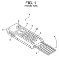
- Fig. 1 shows a prior-art portable telephone equipped with such a cover for the operating part.
- an operating part 3 provided with telephone number input keys and various function buttons, is disposed at the lower-half portion of the front face of a main casing 2 of a portable telephone 1.
- This operating part 3 is disposed in a recessed part 3A formed in the main casing 2 so that when an opening/closing cover 4 is folded and closed, the front face of this opening/closing cover 4 will be flush with the front face of the main casing 2.
- the opening/closing cover 4 has its base end part pivotally supported on the lower end part of the main casing 2 and is thereby mounted to the main casing 2 in a manner enabling opening and closing.
- Fig. 1 denotes a display panel
- 6 denotes an antenna
- 7 denotes a speaker
- 8 denotes a switch or other form of operating lever.
- the opening/closing cover 4 is folded with respect to the main casing 2 and fitted inside the recessed part 3A of the main casing 2 so that the operating part 3, which is disposed in this recessed part 3A, is housed at the inner side and unexposed to the exterior.
- the opening/closing cover 4 is raised from the main casing 2 and opened so that the operating part 3 will be exposed to the exterior.
- Such a portable telephone 1, equipped with the opening/closing cover 4 that houses the operating part 3, has the advantage that, by disposing a microphone and a part of the function buttons at the opening/closing cover 4 side, the outer dimensions of the condition in which the opening/closing cover 4 is folded can be made more compact in comparison to a portable phone that is not equipped with an opening/closing cover, and since in the standby condition, the operating part 3 is housed at the inner side of the folded opening/closing cover 4 and is not exposed to the exterior, the input keys, etc. are protected and erroneous operation due to erroneous pressing of the operating part 3 is prevented.
- the operating part 3 is disposed within the recessed part 3A for housing the opening/closing cover 4 in the main casing 2, when the opening/closing cover 4 is opened, the operating part 3 is positioned at a position that is recessed from the front face of the main casing 2 and is made difficult to operate.
- the operability becomes poor due to the difference in the stroke of the fingers required for operation, since an offset is formed between the operating part 3 disposed on the main casing 2 and the operating part disposed on the opening/closing cover 4.
- the opening/closing cover extends to the outer side of the main casing when the opening/closing cover is opened, the outer shape of the portable phone during use becomes even larger, making the phone unfit for portable use.
- a portable telephone comprising an opening/closing cover which can be brought in an opened position in which an angle is formed between the back face of the opening/closing cover and an operating surface of an operating panel.
- the operating panel is positioned within a main casing of the telephone and can be moved from one position at the inner side of the main casing to another position at the inner side of the main casing.
- This invention has been made to resolve the above-described problems of portable telephones and other portable information terminals.
- This invention has also been made to solve the above-described problems of prior-art portable telephones with an opening/closing cover that houses the operating part.
- An object of this invention is to secure good operability in a portable telephone equipped with an opening/closing cover that houses the operating part.
- the operating panel when the opening/closing cover is closed as in the standby condition of the portable telephone, the operating panel is positioned at the position at the inner side of the main casing and is housed at the inner side of the opening/closing cover.
- the moving part is actuated by the opening operation of the opening/closing cover and the operating panel is moved from the position at the inner side to the position at the front face side of the main casing, and when the opening/closing cover is opened completely and is positioned at the opened position, the operating surface of the operating panel that has been moved by the moving part becomes substantially flush with the back face (the surface that becomes the front face when the opening/closing cover is at the opened position) of the opening/closing cover that is positioned at the opened position.
- the opening/closing cover of a portable telephone equipped with the opening/closing cover when the opening/closing cover of a portable telephone equipped with the opening/closing cover is opened, an offset does not form between the back face of the opening/closing cover at the opened position and the operating surface of the operating panel. Therefore even when a part of the operation part is disposed on the back face of the opening/closing cover, the operating part disposed at this opening/closing cover and the operating part of the operating panel can be operated by the same stroke of the fingers and good operability can thus be secured.
- a portable telephone has, in addition to the arrangement according to the first aspect of this invention, a characteristic that a part of the above mentioned operating part is disposed at the back face side of the above mentioned opening/closing cover.
- the outer shape of the portable telephone can thereby be made compact and good operability is secured by the operating part disposed on the opening/closing cover and the operating part of the operating panel being positioned substantially within the same plane.
- a portable telephone has, in addition to the arrangement according to the first aspect of this invention, the characteristic that the above mentioned moving part is a resilient member that is interposed between the operating panel and the main casing and urges the operating panel in the direction of the position at the front face side of the main casing, and when the opening/closing cover is opened, the operating panel is moved from the position at the inner side towards the position at the front face side of the main casing by being urged by the resilient member.
- a portable telephone has, in addition to the arrangement according to the first aspect of this invention, the characteristic that the above mentioned moving part is an arm member, which is provided on the opening/closing cover and, in accompaniment with the opening operation of the opening/closing cover, engages with the above mentioned operating panel to urge the operating panel in the direction of the position at the front face side of the main casing, and when the opening/closing cover is opened, the operating panel is moved from the position at the inner side towards the position at the front face side of the main casing by being urged by the arm member.
- the above mentioned moving part is an arm member, which is provided on the opening/closing cover and, in accompaniment with the opening operation of the opening/closing cover, engages with the above mentioned operating panel to urge the operating panel in the direction of the position at the front face side of the main casing, and when the opening/closing cover is opened, the operating panel is moved from the position at the inner side towards the position at the front face side of the main casing by being urged by the arm member.
- a portable telephone has, in addition to the arrangement according to the first aspect of this invention, the characteristic of being equipped with a movable member, which is mounted to the operating panel in a manner enabling movement relative to the operating panel and, by the urging force that accompanies the opening operation of the opening/closing cover, is moved in the direction of engaging with the main casing and becomes latched to the main casing to position the operating panel at the position at the front face side of the main casing.
- the urging force that is generated in accompaniment with this opening operation of the opening/closing cover is applied to the movable member and the movable member is moved in the direction of engaging with the main casing.
- the movable member becomes latched to the main casing and the operating panel is thereby positioned at the position at the front face side of the main casing at which it becomes substantially flush with the back face of the opening/closing cover that is at the opened position.
- a portable telephone has, in addition to the arrangement according to the fifth aspect of this invention, the characteristic that a disengaging member, which, when the urging force on said movable member is relieved, urges the engaged movable member in the direction of disengaging from the main casing, is provided at the part of the main casing with which the above mentioned movable member engages.
- the disengaging member urges the movable member in the direction opposite that when the opening/closing cover is opened and disengages the movable member from the main casing, thereby enabling the movement of the operating panel from the position at the front face side towards the position at the inner side of the main casing.
- a portable telephone has, in addition to the arrangement according to the first aspect of this invention, the characteristic that the above mentioned main casing is equipped with an opened/closed condition detection part, which detects that the opening/closing cover is opened and thereupon sets the above mentioned operating part in the condition that enables operation. Since the operation of the operating part is thereby enabled when the opening/closing cover is opened and the operation of the operating part is disabled when the opening/closing cover is closed, erroneous operation is prevented and saving of power is achieved.
- a portable telephone has, in addition to the arrangement according to the first aspect of this invention, the characteristic that the above mentioned opening/closing cover is mounted to the main casing at a position such that the opening direction will be at the display panel side of the portable telephone.
- the enlargement of the outer shape of the portable telephone when the opening/closing cover is opened can thereby be prevented.
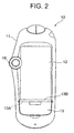
- Fig. 2 is a front view, which shows a portable telephone equipped with cover opening/closing mechanism by this invention in the standby condition
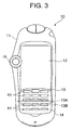
- Fig. 3 is a front view, which shows this portable telephone in the operated condition.
- a portable telephone 10 has a display panel 12 disposed at the central part of the surface of a main casing 11, and an opening/closing cover 13 is mounted to the lower part of this display panel 12.
- the opening/closing cover 13 has its upper end part (the right end part in Fig. 4) mounted by a parallel shaft 13A to the bottom edge (the left edge in Fig. 4) of the display panel 12 in a manner enabling rotation in the vertical direction (left/right direction in Fig. 4) with respect to the main casing 11.
- the position of the opening/closing cover 13 is set so that when the opening/closing cover 13 is at the closed position with respect to the main casing 11, the surface will be substantially flush with the surface of the main casing 11, and the position of the display panel 12 is set so that it will be positioned to the inner side of the main casing 11 substantially by just the thickness of the opening/closing cover 13.
- the opening/closing cover-13 has an integrally formed arm part 13B, which, in the condition where the opening/closing cover 13 is at the closed position with respect to the main casing 11, extends from the position of shaft 13A to the side of the display panel 12.
- the upper edge (the right edge in Fig. 4) of this arm part 13B is positioned just at the same position as the lower edge (the left edge in Fig. 4) of the display panel 12 so that when the portable telephone 10 is viewed from the front, a gap cannot be seen between the display panel 12 and the arm part 13B.
- An inclined surface 13Ba which is inclined downwards (leftwards in Fig. 3) from the front face to the back face is formed on the front end part of the arm part 13B.
- An operating panel 14 is fitted in a manner enabling rising and lowering onto the portion of the main casing 11 that is covered by the opening/closing cover 13, and at the back face side of this operating panel 14, an ascending/descending support plate 15 is joined to the operating panel 14 in a manner that does not allow separation but enables sliding in the vertical direction (left/right direction in Fig. 4) by the fitting of unillustrated fitting grooves formed on the mutual joining surfaces.
- First operating buttons K1 such as telephone number input keys, function keys, etc., are disposed on the front face of the operating panel 14 and second operating buttons K2 are disposed on the back face side of the opening/closing cover 13.
- a compression spring 16 is interposed between the back face of the ascending/descending support plate 15 and a frame part 11A, which is formed in an integral manner on the inner side of the main casing 11, and this compression spring 16 urges the ascending/descending support plate 15 and the operating panel 14 towards the front face side of the main casing 11.
- An inclined surface 15a which is inclined downwards (leftwards in Fig. 4) from the front face to the back face, is formed on the upper end part of the ascending/descending support plate 15.
- a recessed part 11Aa into which the ascending/descending support plate 15 in the raised position fits upon sliding in the downward direction (leftward direction in Fig. 4) of the main casing 11, is formed on frame part 11A of main casing 11.
- a spring 17 which is compressed by the entering ascending/descending support plate 15, and an unillustrated opened/closed condition detection switch, which, by being pressed and turned on by the further entry of the ascending/descending support plate 15, conducts power to the first operating buttons K1 disposed on the operating panel 14 and the second operating buttons K2 disposed on the opening/closing cover 13 to enable their operation.
- Figs. 2 and 3 19 denotes an operating dial for performing the operation of switching the display screen, etc. of the display panel 12.
- the opening/closing cover 13 is closed so as to cover the operating panel 14 as shown in Fig. 2 and is latched to the main casing 11 by the engagement of an unillustrated engaging part.
- the opening/closing cover 13 is opened by rotating it about the shaft 13A in the upward direction with respect to the main casing 11 so that the operating panel, 14 will be exposed as shown in Fig. 3.
- the arm part 13B which rotates and enters inside the main casing 11 in accompaniment with the upward (rightward in Fig. 5) rotation of the opening/closing cover 13 about the shaft 13A, comes in contact with the upper end parts (right end parts in Fig. 5) of the operating panel 14 and the ascending/descending support plate 15 from below.
- the arm part 13B then supportingly raises the upper end parts of the operating panel 14 and the ascending/descending support plate 15 in accompaniment with this rotation of the opening/closing cover 13, and the ascending/descending support plate 15 becomes urged in the downward direction (leftward direction in Fig. 5) of the main casing 11 by the sliding of the inclined surface 13Ba of the arm part 13B against the inclined surface 15a of the ascending/descending support plate 15.
- the opening/closing cover 13 becomes completely opened as shown in Fig. 6, the opening/closing cover 13 becomes positioned at a position on the display panel 12 where the back face (operating surface) on which the second operating buttons K2 are disposed will be substantially flush with the front face of the main casing 11.
- the lower end part (left end part in Fig. 6) of the ascending/descending support plate 15 becomes fitted into the recessed part 11Aa, formed on frame part 11A of the main casing 11, while compressing the spring 17, and the ascending/descending support plate 15 and the operating panel 14, which is joined to the ascending/descending support plate 15 in an inseparable manner, become latched to the main casing 11 and thereby prevented from rising further.
- the operating panel 14 is positioned at a position at which the front side operating surface on which the first operating buttons K1 are disposed will be substantially flush with the front face of the main casing 11.
- the operating panel 14 is raised and the operating surface, on which the first operating buttons K1 are disposed, and the operating surface (back face) of the opening/closing cover 13, on which the second operating buttons K2 are disposed, become aligned in substantially the same plane.
- the unillustrated opened/closed condition detection switch mounted inside recessed part 11Aa, comes in contact with the end part of the ascending/descending support plate 15 that has been fitted inside this recessed part 11Aa and is thereby turned on to conduct power and thus enable operation by first operating buttons K1 and second operating buttons K2.
- the opening/closing cover 13 then becomes latched to the main casing 11 by means of an unillustrated engaging part and, as shown in Fig. 2, the operating surface of the operating panel 14 becomes completely housed at the inner side of the opening/closing cover 13 so as to become unable to be seen from the outer side.
Landscapes
- Engineering & Computer Science (AREA)
- Signal Processing (AREA)
- Telephone Set Structure (AREA)
Claims (8)
- Tragbares Telefon, das mit einer öffnenden/ schließenden Abdeckung (13) ausgestattet ist, die geöffnet und geschlossen werden kann, und mit einem Betriebsteil (K1),
dadurch gekennzeichnet, dass das tragbare Telefon mit einem Betätigungsfeld (14) ausgestattet ist, das das Betätigungsteil (K1) umfasst und an einem Hauptgehäuse (11) des tragbaren Telefons auf eine Weise angebracht ist, die eine Bewegung zwischen einer Position an der Vorderseite und einer Position an der Innenseite des Hauptgehäuses (11) ermöglicht, und
einem Bewegungsteil (15, 16) ausgestattet ist, das das Betätigungsfeld (14) zwischen der Position an der Vorderseite und der Position an der Innenseite des Hauptgehäuses (11) bewegt,
dass, wenn die öffnende/schließende Abdeckung (13) sich in der geschlossenen Position befindet, das Betätigungsfeld (14) in dem Hauptgehäuse (11) unterhalb der öffnenden/schließenden Abdeckung (13) untergebracht ist, und, wenn die öffnenden/schließenden Abdeckung (13) geöffnet ist, das Betätigungsfeld (14) in die Position an der Vorderseite des Hauptgehäuses (11) durch das Bewegungsteil (15, 16) gemäß der Öffnungsbetätigung der öffnenden/schließenden Abdeckung (13) bewegt ist,
dass sich die Rückseite der öffnenden/schließenden Abdeckung (13) in der geöffneten Position auf einer Höhe relativ zu dem Hauptgehäuse (11) befindet, die im Wesentlichen identisch mit einer Höhe einer Außenseite der öffnenden/schließenden Abdeckung (13) in einer geschlossenen Position ist,
und dass die Betätigungsfläche des Betätigungsfeldes (14) in einer Position positioniert ist, in der sie im Wesentlichen fluchtend mit der Rückseite der öffnenden/ schließenden Abdeckung (13), die in der geöffneten Position positioniert ist, angeordnet ist. - Tragbares Telefon nach Anspruch 1, wobei ein Teil (K2) des Betätigungsteils an der Rückseite der öffnenden/schließenden Abdeckung (13) angeordnet ist.
- Tragbares Telefon nach Anspruch 1, wobei das Bewegungsteil ein elastisches Element (16) ist, das zwischen dem Betätigungsfeld (14) und dem Hauptgehäuse (11) angeordnet ist und das Betätigungsfeld (14) in der Richtung der Position an der Vorderseite des Hauptgehäuses (11) treibt.
- Tragbares Telefon nach Anspruch 1, wobei das Bewegungsteil ein Armelement (13B) ist, das an der öffnenden/ schließenden Abdeckung (13) vorgesehen ist, und in Begleitung der Öffnungsbetätigung der öffnenden/schließenden Abdeckung (13) mit dem Betätigungsfeld (14) in Eingriff tritt, um das Betätigungsfeld (14) in der Richtung der Position an der Vorderseite des Hauptgehäuses (11) zu treiben.
- Tragbares Telefon nach Anspruch 1, das mit einem bewegbaren Element (15) ausgestattet ist, das an dem Betätigungsfeld (14) auf eine Weise angebracht ist, die eine Bewegung relativ zu dem Betätigungsfeld (14) ermöglicht, und das durch die Treibkraft, die die Öffnungsbetätigung der öffnenden/schließenden Abdeckung (13) begleitet, in der Richtung des Eingriffs mit dem Hauptgehäuse (11) bewegt wird und mit dem Hauptgehäuse (11) verriegelt wird, um das Betätigungsfeld (14) an der Position an der Vorderseite des Hauptgehäuses (11) zu positionieren.
- Tragbares Telefon nach Anspruch 5, wobei ein Ausrückelement (17), das, wenn die Treibkraft an dem bewegbaren Element (15) entlastet wird, das eingerückte bewegbare Element in der Richtung eines Ausrückens von dem Hauptgehäuse (11) treibt, an dem Teil des Hauptgehäuses (11), mit dem das bewegbare Element in Eingriff tritt, vorgesehen ist.
- Tragbares Telefon nach Anspruch 1, wobei das Hauptgehäuse (11) mit einem Teil zur Detektion eines geöffneten/geschlossenen Zustands ausgestattet ist, das detektiert, dass die öffnende/schließende Abdeckung (13) geöffnet ist und daraufhin das Öffnungs- [Teil] -Feld (14) in den Zustand versetzt, der eine Betätigung ermöglicht.
- Tragbares Telefon nach Anspruch 1, wobei die öffnende/schließende Abdeckung (13) an dem Hauptgehäuse (11) in einer Position angebracht ist, so dass die Öffnungsrichtung sich an der Seite des Displayfeldes (12) des tragbaren Telefons befindet.
Applications Claiming Priority (4)
| Application Number | Priority Date | Filing Date | Title |
|---|---|---|---|
| JP2000169132 | 2000-06-06 | ||
| JP2000169132A JP3907388B2 (ja) | 2000-06-06 | 2000-06-06 | 携帯電話機 |
| JP2000176617 | 2000-06-13 | ||
| JP2000176617A JP3942808B2 (ja) | 2000-06-13 | 2000-06-13 | 携帯情報端末機 |
Publications (3)
| Publication Number | Publication Date |
|---|---|
| EP1162811A2 EP1162811A2 (de) | 2001-12-12 |
| EP1162811A3 EP1162811A3 (de) | 2004-06-30 |
| EP1162811B1 true EP1162811B1 (de) | 2006-12-06 |
Family
ID=26593411
Family Applications (1)
| Application Number | Title | Priority Date | Filing Date |
|---|---|---|---|
| EP01113753A Expired - Lifetime EP1162811B1 (de) | 2000-06-06 | 2001-06-05 | Tragbares Telefon |
Country Status (4)
| Country | Link |
|---|---|
| US (1) | US6807276B2 (de) |
| EP (1) | EP1162811B1 (de) |
| CN (1) | CN1206813C (de) |
| DE (1) | DE60124983T2 (de) |
Families Citing this family (16)
| Publication number | Priority date | Publication date | Assignee | Title |
|---|---|---|---|---|
| JP3606498B2 (ja) * | 1996-04-26 | 2005-01-05 | 三菱電機株式会社 | 携帯情報端末装置 |
| KR100396271B1 (ko) * | 2001-08-23 | 2003-09-02 | 삼성전자주식회사 | 자동 및 수동 겸용 접이형 휴대용 무선단말기 |
| JP3979090B2 (ja) * | 2001-12-28 | 2007-09-19 | 日本電気株式会社 | カメラ付き携帯型電子機器 |
| USD482010S1 (en) | 2002-05-20 | 2003-11-11 | Nokia Corporation | Handset |
| JP3726070B2 (ja) * | 2002-05-28 | 2005-12-14 | Necアクセステクニカ株式会社 | 携帯無線端末 |
| US20040204000A1 (en) * | 2002-05-30 | 2004-10-14 | Aaron Dietrich | Mobile communication device including an array sensor |
| US7085542B2 (en) * | 2002-05-30 | 2006-08-01 | Motorola, Inc. | Portable device including a replaceable cover |
| US6879842B2 (en) * | 2002-05-31 | 2005-04-12 | Lavaflow, Llp | Foldable wireless communication device functioning as a cellular telephone and a personal digital assistant |
| US7010333B2 (en) * | 2003-02-19 | 2006-03-07 | Sony Ericsson Mobile Communications Ab | Radiotelephone terminal with dual-sided keypad apparatus |
| WO2004109494A1 (en) | 2003-06-05 | 2004-12-16 | Nokia Corporation | Method and software application for transmitting information remaining behind an obstacle located in front of the display to the user of a data processing device |
| US20060120029A1 (en) * | 2004-12-03 | 2006-06-08 | Gwan-Woo Ryu | Portable terminal having protruding keypad |
| CN101645719A (zh) * | 2008-08-07 | 2010-02-10 | 深圳富泰宏精密工业有限公司 | 便携式个人终端及其图标设定方法 |
| TWI365058B (en) * | 2009-07-23 | 2012-06-01 | Top Victory Invest Ltd | Digital photo frame with slide structure |
| US20120081275A1 (en) * | 2010-10-05 | 2012-04-05 | Microsoft Corporation | Media Display Device |
| CN103544676B (zh) * | 2012-07-16 | 2016-12-28 | 联想(北京)有限公司 | 图像处理方法及电子设备 |
| WO2021082007A1 (zh) * | 2019-11-01 | 2021-05-06 | 深圳市汇顶科技股份有限公司 | 设备开合盖检测的方法、触摸控制器、触控板和电子设备 |
Family Cites Families (6)
| Publication number | Priority date | Publication date | Assignee | Title |
|---|---|---|---|---|
| JPH04281628A (ja) * | 1991-03-11 | 1992-10-07 | Matsushita Electric Ind Co Ltd | 携帯形無線機 |
| US5519569A (en) | 1994-06-30 | 1996-05-21 | Compaq Computer Corporation | Compact notebook computer having a foldable and collapsible keyboard structure |
| JP3606498B2 (ja) * | 1996-04-26 | 2005-01-05 | 三菱電機株式会社 | 携帯情報端末装置 |
| CN1113519C (zh) | 1997-10-01 | 2003-07-02 | 日本电气株式会社 | 便携无线电通信装置 |
| US6038313A (en) | 1997-11-20 | 2000-03-14 | Nortel Networks Corporation | Double sided keyboard for a telephone |
| FI114267B (fi) | 1998-01-29 | 2004-09-15 | Nokia Corp | Elektroninen laite ja menetelmä tietojen näyttämiseksi |
-
2001
- 2001-06-04 US US09/871,702 patent/US6807276B2/en not_active Expired - Fee Related
- 2001-06-05 EP EP01113753A patent/EP1162811B1/de not_active Expired - Lifetime
- 2001-06-05 DE DE60124983T patent/DE60124983T2/de not_active Expired - Fee Related
- 2001-06-06 CN CN01115751.8A patent/CN1206813C/zh not_active Expired - Fee Related
Also Published As
| Publication number | Publication date |
|---|---|
| CN1206813C (zh) | 2005-06-15 |
| US20020018558A1 (en) | 2002-02-14 |
| DE60124983D1 (de) | 2007-01-18 |
| CN1332525A (zh) | 2002-01-23 |
| EP1162811A2 (de) | 2001-12-12 |
| EP1162811A3 (de) | 2004-06-30 |
| US6807276B2 (en) | 2004-10-19 |
| DE60124983T2 (de) | 2007-06-14 |
Similar Documents
| Publication | Publication Date | Title |
|---|---|---|
| EP1162811B1 (de) | Tragbares Telefon | |
| JP2689880B2 (ja) | 携帯電話機 | |
| US6963756B2 (en) | Electronic equipment comprising a retractable screen | |
| US6819947B2 (en) | Foldable portable telephone | |
| US20050064921A1 (en) | Sliding-type portable wireless terminal and method for controlling sliding movement in the same | |
| JP2003319044A (ja) | 携帯電話機 | |
| KR20020035752A (ko) | 전환 장치 | |
| US6642462B2 (en) | Lid open/close detection device of portable electronic equipment | |
| US20080100262A1 (en) | Mobile terminal device | |
| KR100340481B1 (ko) | 복합조작형 전기부품 | |
| JP4557352B2 (ja) | ケースに連結されたフラップを有する携帯電話装置 | |
| KR100781996B1 (ko) | 슬라이드 다운 개폐방식 휴대 단말기 | |
| KR100689378B1 (ko) | 휴대용 단말기의 힌지 장치 | |
| JP3907388B2 (ja) | 携帯電話機 | |
| US20010039193A1 (en) | Sensor for detecting the state of a cover of a cellular phone | |
| TW522417B (en) | Open-close detection apparatus | |
| KR100617152B1 (ko) | 사이드 버튼 장치 | |
| JP2540427Y2 (ja) | ワンピース型電話機 | |
| KR200214829Y1 (ko) | 엘씨디 부분이 움직이는 슬라이더형 휴대폰 | |
| CN1151694C (zh) | 用来检测移动电话的保护盖开关状态的感应装置 | |
| KR19990060370A (ko) | 플립형 휴대용 단말기의 플립커버 개폐 장치 | |
| KR0120647Y1 (ko) | 휴대용 주파수공용 통신 단말기의 푸시버튼 조립구조 | |
| JPH018047Y2 (de) | ||
| KR200181624Y1 (ko) | 휴대용 전화기의 회전방식 상하 스크롤 키 | |
| JP3731222B2 (ja) | ファクシミリ装置 |
Legal Events
| Date | Code | Title | Description |
|---|---|---|---|
| PUAI | Public reference made under article 153(3) epc to a published international application that has entered the european phase |
Free format text: ORIGINAL CODE: 0009012 |
|
| AK | Designated contracting states |
Kind code of ref document: A2 Designated state(s): AT BE CH CY DE DK ES FI FR GB GR IE IT LI LU MC NL PT SE TR |
|
| AX | Request for extension of the european patent |
Free format text: AL;LT;LV;MK;RO;SI |
|
| RIC1 | Information provided on ipc code assigned before grant |
Ipc: 7G 06F 3/033 B Ipc: 7H 04M 1/247 B Ipc: 7G 06F 1/16 B Ipc: 7G 06F 3/02 B Ipc: 7H 04M 1/02 A |
|
| PUAL | Search report despatched |
Free format text: ORIGINAL CODE: 0009013 |
|
| AK | Designated contracting states |
Kind code of ref document: A3 Designated state(s): AT BE CH CY DE DK ES FI FR GB GR IE IT LI LU MC NL PT SE TR |
|
| AX | Request for extension of the european patent |
Extension state: AL LT LV MK RO SI |
|
| 17P | Request for examination filed |
Effective date: 20040624 |
|
| 17Q | First examination report despatched |
Effective date: 20040809 |
|
| AKX | Designation fees paid |
Designated state(s): DE FR GB |
|
| GRAP | Despatch of communication of intention to grant a patent |
Free format text: ORIGINAL CODE: EPIDOSNIGR1 |
|
| RAP1 | Party data changed (applicant data changed or rights of an application transferred) |
Owner name: PIONEER DESIGN CORPORATION Owner name: PIONEER CORPORATION |
|
| GRAS | Grant fee paid |
Free format text: ORIGINAL CODE: EPIDOSNIGR3 |
|
| GRAA | (expected) grant |
Free format text: ORIGINAL CODE: 0009210 |
|
| AK | Designated contracting states |
Kind code of ref document: B1 Designated state(s): DE FR GB |
|
| REG | Reference to a national code |
Ref country code: GB Ref legal event code: FG4D |
|
| REF | Corresponds to: |
Ref document number: 60124983 Country of ref document: DE Date of ref document: 20070118 Kind code of ref document: P |
|
| ET | Fr: translation filed | ||
| REG | Reference to a national code |
Ref country code: GB Ref legal event code: 746 Effective date: 20070524 |
|
| PGFP | Annual fee paid to national office [announced via postgrant information from national office to epo] |
Ref country code: DE Payment date: 20070831 Year of fee payment: 7 |
|
| PLBE | No opposition filed within time limit |
Free format text: ORIGINAL CODE: 0009261 |
|
| STAA | Information on the status of an ep patent application or granted ep patent |
Free format text: STATUS: NO OPPOSITION FILED WITHIN TIME LIMIT |
|
| 26N | No opposition filed |
Effective date: 20070907 |
|
| PGFP | Annual fee paid to national office [announced via postgrant information from national office to epo] |
Ref country code: GB Payment date: 20070629 Year of fee payment: 7 |
|
| PGFP | Annual fee paid to national office [announced via postgrant information from national office to epo] |
Ref country code: FR Payment date: 20070615 Year of fee payment: 7 |
|
| GBPC | Gb: european patent ceased through non-payment of renewal fee |
Effective date: 20080605 |
|
| REG | Reference to a national code |
Ref country code: FR Ref legal event code: ST Effective date: 20090228 |
|
| PG25 | Lapsed in a contracting state [announced via postgrant information from national office to epo] |
Ref country code: DE Free format text: LAPSE BECAUSE OF NON-PAYMENT OF DUE FEES Effective date: 20090101 |
|
| PG25 | Lapsed in a contracting state [announced via postgrant information from national office to epo] |
Ref country code: GB Free format text: LAPSE BECAUSE OF NON-PAYMENT OF DUE FEES Effective date: 20080605 |
|
| PG25 | Lapsed in a contracting state [announced via postgrant information from national office to epo] |
Ref country code: FR Free format text: LAPSE BECAUSE OF NON-PAYMENT OF DUE FEES Effective date: 20080630 |