EP1162855A1 - Optisches Wellenlängenmultiplexiertes Netz mit gemischten Wellenlängen Leitweglenkung und optischen Fasern Leitweglenkung - Google Patents
Optisches Wellenlängenmultiplexiertes Netz mit gemischten Wellenlängen Leitweglenkung und optischen Fasern Leitweglenkung Download PDFInfo
- Publication number
- EP1162855A1 EP1162855A1 EP00111791A EP00111791A EP1162855A1 EP 1162855 A1 EP1162855 A1 EP 1162855A1 EP 00111791 A EP00111791 A EP 00111791A EP 00111791 A EP00111791 A EP 00111791A EP 1162855 A1 EP1162855 A1 EP 1162855A1
- Authority
- EP
- European Patent Office
- Prior art keywords
- switch
- optical
- network
- node
- fibers
- Prior art date
- Legal status (The legal status is an assumption and is not a legal conclusion. Google has not performed a legal analysis and makes no representation as to the accuracy of the status listed.)
- Granted
Links
- 230000003287 optical effect Effects 0.000 title claims abstract description 102
- 239000000835 fiber Substances 0.000 title claims abstract description 91
- 239000013307 optical fiber Substances 0.000 claims description 55
- 238000011144 upstream manufacturing Methods 0.000 claims description 6
- 230000001172 regenerating effect Effects 0.000 claims description 2
- 210000001520 comb Anatomy 0.000 description 20
- 230000005540 biological transmission Effects 0.000 description 15
- 238000000034 method Methods 0.000 description 10
- 230000008901 benefit Effects 0.000 description 9
- 238000005516 engineering process Methods 0.000 description 9
- 239000011159 matrix material Substances 0.000 description 8
- 230000008569 process Effects 0.000 description 8
- 230000008929 regeneration Effects 0.000 description 7
- 238000011069 regeneration method Methods 0.000 description 7
- 238000004891 communication Methods 0.000 description 5
- 238000010586 diagram Methods 0.000 description 4
- 239000004744 fabric Substances 0.000 description 3
- 239000000463 material Substances 0.000 description 3
- 238000012545 processing Methods 0.000 description 3
- 230000008859 change Effects 0.000 description 2
- 238000010276 construction Methods 0.000 description 2
- 230000003247 decreasing effect Effects 0.000 description 2
- 230000010354 integration Effects 0.000 description 2
- 230000006978 adaptation Effects 0.000 description 1
- 230000003321 amplification Effects 0.000 description 1
- 230000009286 beneficial effect Effects 0.000 description 1
- 238000006243 chemical reaction Methods 0.000 description 1
- 238000007728 cost analysis Methods 0.000 description 1
- 230000008878 coupling Effects 0.000 description 1
- 238000010168 coupling process Methods 0.000 description 1
- 238000005859 coupling reaction Methods 0.000 description 1
- 230000007423 decrease Effects 0.000 description 1
- 230000006735 deficit Effects 0.000 description 1
- 239000006185 dispersion Substances 0.000 description 1
- 238000011156 evaluation Methods 0.000 description 1
- 238000007726 management method Methods 0.000 description 1
- 239000000203 mixture Substances 0.000 description 1
- 238000012986 modification Methods 0.000 description 1
- 230000004048 modification Effects 0.000 description 1
- 238000003199 nucleic acid amplification method Methods 0.000 description 1
- 230000010287 polarization Effects 0.000 description 1
- 238000012958 reprocessing Methods 0.000 description 1
Images


Classifications
-
- H—ELECTRICITY
- H04—ELECTRIC COMMUNICATION TECHNIQUE
- H04J—MULTIPLEX COMMUNICATION
- H04J14/00—Optical multiplex systems
- H04J14/02—Wavelength-division multiplex systems
- H04J14/0287—Protection in WDM systems
- H04J14/0293—Optical channel protection
- H04J14/0295—Shared protection at the optical channel (1:1, n:m)
-
- H—ELECTRICITY
- H04—ELECTRIC COMMUNICATION TECHNIQUE
- H04Q—SELECTING
- H04Q11/00—Selecting arrangements for multiplex systems
- H04Q11/0001—Selecting arrangements for multiplex systems using optical switching
- H04Q11/0005—Switch and router aspects
-
- H—ELECTRICITY
- H04—ELECTRIC COMMUNICATION TECHNIQUE
- H04J—MULTIPLEX COMMUNICATION
- H04J14/00—Optical multiplex systems
- H04J14/02—Wavelength-division multiplex systems
- H04J14/0278—WDM optical network architectures
- H04J14/0284—WDM mesh architectures
-
- H—ELECTRICITY
- H04—ELECTRIC COMMUNICATION TECHNIQUE
- H04Q—SELECTING
- H04Q11/00—Selecting arrangements for multiplex systems
- H04Q11/0001—Selecting arrangements for multiplex systems using optical switching
- H04Q11/0062—Network aspects
- H04Q11/0066—Provisions for optical burst or packet networks
-
- H—ELECTRICITY
- H04—ELECTRIC COMMUNICATION TECHNIQUE
- H04Q—SELECTING
- H04Q11/00—Selecting arrangements for multiplex systems
- H04Q11/0001—Selecting arrangements for multiplex systems using optical switching
- H04Q11/0005—Switch and router aspects
- H04Q2011/0007—Construction
- H04Q2011/0016—Construction using wavelength multiplexing or demultiplexing
-
- H—ELECTRICITY
- H04—ELECTRIC COMMUNICATION TECHNIQUE
- H04Q—SELECTING
- H04Q11/00—Selecting arrangements for multiplex systems
- H04Q11/0001—Selecting arrangements for multiplex systems using optical switching
- H04Q11/0005—Switch and router aspects
- H04Q2011/0007—Construction
- H04Q2011/0024—Construction using space switching
-
- H—ELECTRICITY
- H04—ELECTRIC COMMUNICATION TECHNIQUE
- H04Q—SELECTING
- H04Q11/00—Selecting arrangements for multiplex systems
- H04Q11/0001—Selecting arrangements for multiplex systems using optical switching
- H04Q11/0005—Switch and router aspects
- H04Q2011/0052—Interconnection of switches
-
- H—ELECTRICITY
- H04—ELECTRIC COMMUNICATION TECHNIQUE
- H04Q—SELECTING
- H04Q11/00—Selecting arrangements for multiplex systems
- H04Q11/0001—Selecting arrangements for multiplex systems using optical switching
- H04Q11/0062—Network aspects
- H04Q2011/0079—Operation or maintenance aspects
- H04Q2011/0081—Fault tolerance; Redundancy; Recovery; Reconfigurability
-
- H—ELECTRICITY
- H04—ELECTRIC COMMUNICATION TECHNIQUE
- H04Q—SELECTING
- H04Q11/00—Selecting arrangements for multiplex systems
- H04Q11/0001—Selecting arrangements for multiplex systems using optical switching
- H04Q11/0062—Network aspects
- H04Q2011/0086—Network resource allocation, dimensioning or optimisation
Definitions
- the present invention relates generally to optical networks that employ wavelength division multiplexing and, more particularly, to optical networks that use optical cross-connect switches in transit and hub nodes.
- Wavelength division multiplexing provides a technique to accommodate increased traffic in existing long distance telecommunication networks.
- WDM takes advantage of the large bandwidth of optical fibers and sends multiple communications down a single optical fiber in separate wavelength channels. As a result, a WDM system can multiply the capacity of the system compared with the use of only a single wavelength.
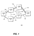
- FIG. 1 illustrates an optical network 100 having links such as 105, 110, and 115 interconnecting nodes such as nodes A, B, and C.
- Link 105 has 6 fibers (each line representing 2 fibers)
- link 110 has 4 fibers
- link 115 has 2 fibers. Coordinating these differences in fiber capacity presents challenges to the cross-connect switches within nodes A, B, and C.
- nodes A-F are equipped with OXCs whose task is to switch the optical channels coming from N input fibers to N output fibers.
- OXCs fiber-routing cross-connect switches
- WR-OXCs wavelength-routing cross-connect switches
- combinations of them FR-OXCs are also known as optical switches.
- FIG. 2 illustrates a typical scheme of a WR-OXC.
- the WR-OXC performs routing channel by channel, thereby allowing channels from the same input fiber to be sent to different output fibers.
- WR-OXC 200 includes demultiplexers 205 and 210 for separating the signals traveling in received WDM combs via optical fibers 215 and 220.
- optional 3R regenerators or transponders 225 and 230 can provide both signal regeneration and wavelength adaptation for each of the wavelengths entering WR-OXC switch 235.
- Transponders 225 and 230 if present, convert the wavelengths to a grid used particularly by switch 235 and are typically realized by electro-optic techniques.
- This wavelength conversion makes the large network opaque with respect to carrier wavelengths, although all-optical networks are envisioned for the future that perform all phases of transmission, amplification, and switching in the optical domain.
- the respective wavelengths can pass through optional output transponders 240 and 245, are combined in multiplexers 250 and 255, and exit via optical fibers 260 and 265.
- Optional output transponders 240 and 245 can convert the carrier wavelengths to the particular value required by the network downstream of WR-OXC 200.
- an FR-OXC has the task of switching entire optical WDM combs between input fibers and output fibers without demultiplexing the optical channels. Adding or dropping of entire WDM combs from or to another optical network entity via the FR-OXC is also possible.
- the FR-OXC is statically configured based on a routing table and is reconfigured when the traffic changes. No regeneration is present in the FR-OXC, since the individual WDM channels are not demultiplexed. It is evident that once the number of input and output optical fibers is fixed, a WR-OXC has more switching versatility than an FR-OXC. Due to this increased complexity, WR-OXCs cost more than FR-OXCs.
- each node processes and switches a certain number of local channels and a certain number of passthrough channels.
- the local channels are generated or terminated at destinations affiliated with the node, while the passthrough channels are routed through the node to elsewhere in the network. If the number of nodes is more than a few dozen, the majority of network nodes generally has many more passthrough channels than local channels. These majority of nodes are called transit nodes. The number of local channels exceeds the number of passthrough channels in only a few nodes, which are called hub nodes.
- Patents and publications have contemplated the combination of WR-OXCs and FR-OXCs into a tandem switch structure in certain circumstances.
- US 5457556 discloses an OXC system having a space switch with first and second inlet ports and first and second outlet ports. The first inlet and first outlet ports receive, switch, and transmit entire WDM combs within the space switch.
- a wavelength switch has first inlet ports connected to the second outlet ports of the space switch via a demultiplexer and first outlet ports connected to the second inlet ports of the space switch via a multiplexer. The wavelength switch receives selected WDM combs from the space switch, switches individual channels between the combs, and sends the switched channels back to the space switch.
- system protection occurs at a fiber or multiplex section level. Because protection switching is accomplished without demultiplexing a WDM comb, all incoming and outgoing fibers enter and exit the tandem OXC via a space switch, i.e. an FR-OXC. Accordingly, each node in the network, which operates with fiber level protection, has at least an FR-OXC as the input and output for the links to other nodes.
- US 5805320 discloses an OXC having a combined FR-OXC and WR-OXC where the FR-OXC handles the bypass component for reserve optical transmission lines in a fiber-level protection scheme termed Type A.
- the WR-OXC is connected to the working optical transmission lines, and connection links interface the two switches together.
- Type B and Type C protection schemes that operate at the channel level, the '320 patent discloses a combination of WR-OXC switches for both the working and reserve optical transmission lines without the use of an FR-OXC.
- an opaque optical network that includes transit nodes and hub nodes can be configured more efficiently and cheaply by incorporating tandem OXCs within transit nodes that use FR-OXCs to switch WDM combs passing through the node and WR-OXCs to switch traffic headed for local destinations, and by incorporating at least WR-OXCs within hub nodes to directly receive and switch local traffic.
- an opaque optical network that has a channel-level protection scheme can be configured more efficiently and cheaply by having at least one OXC node of a tandem FR-OXC and WR-OXC architecture.
- an optical WDM network consistent with the present invention communicates WDM channels to local destinations via a plurality of nodes and interconnecting optical fibers, where the nodes include at least one transit node and at least one hub node.
- the transit node includes a transit switch having a fiber-routing portion (FR) and a wavelength-routing portion (WR), where the fiber-routing portion includes a first group of FR inputs coupled to first network optical fibers and a first group of FR outputs coupled to second network optical fibers.
- the wavelength-routing portion is positioned in a feedback path between a second group of FR outputs and a second group of FR inputs.
- the fiber-routing portion is capable of switching a WDM comb from any of the first and second FR inputs to any of the first and second FR outputs.
- Quantities of the first and second groups of FR outputs of the transit switch are selected such that C FR1 > C WR1 , where C FR1 is a switching capacity of the fiber-routing portion and C WR1 is a switching capacity of the wavelength-routing portion.
- the network also has a hub switch within the hub node that has at least a wavelength-routing portion that includes a first group of WR inputs and a first group of WR outputs.
- the first group of WR inputs is arranged to receive first orders of WDM channels directly from some of third network fibers, and the first group of WR outputs is arranged to transmit second orders of WDM channels to local destination fibers.
- an optical WDM network in another aspect, includes a plurality of first optical fibers each carrying WDM channels from at least one upstream node to a transit node and a plurality of second optical fibers each carrying WDM channels from the transit node to at least one downstream node.
- the network has a transit switch located in the transit node that includes a first optical switch having a plurality of inlets and a plurality of outlets. A first subset of the first-switch inlets is coupled to the first fibers, and a first subset of the first-switch outlets is coupled to the second fibers.
- the transit switch also has a second optical switch with a plurality of inlets and a plurality of outlets and a plurality of input transponders and a plurality of output transponders coupled respectively to the second-switch inlets and the second switch outlets.
- At least one demultiplexer is positioned between at least one of a second subset of the first-switch outlets and ones of the second-switch inlets, and at least one multiplexer is positioned between ones of the second-switch outlets and at least one of a second subset of the first-switch inlets.
- the network of the second aspect further includes a plurality of third optical fibers each carrying WDM channels from at least one upstream node to a hub node, a plurality of fourth optical fibers each carrying WDM channels from the hub node to at least one local destination, and a hub switch located in the at least one hub node.
- the hub switch has at least one demultiplexer coupled to at least one of the third fibers, a plurality of input hub transponders each coupled to a respective output of the at least one demultiplexer, and a third optical switch.
- the third switch in the network of the second aspect has a plurality of inlets coupled to the plurality of input hub transponders and a plurality of outlets, and includes a plurality of output hub transponders coupled to the plurality of third-switch outlets, and at least one multiplexer positioned between the plurality of output hub transponders and the fourth optical fibers.
- an optical WDM network consistent with the present invention has a plurality of nodes interconnected by optical fibers and a channel-level protection scheme.
- the network includes a plurality of first network optical fibers each carrying first WDM channels that have an affiliated first optical channel header with information about the channel-level protection, and a plurality of second network optical fibers each carrying second WDM channels that have an affiliated second optical channel header with information about the channel-level protection.
- the network of the third aspect includes at least one optical cross-connect switch made of a fiber-routing portion (FR) and a wavelength-routing portion (WR).
- the fiber-routing portion includes a first group of FR inputs coupled to the first network optical fibers and a first group of FR outputs coupled to the second network optical fibers.
- the wavelength-routing portion is positioned in a feedback path between a second group of FR outputs and a second group of FR inputs of the fiber-routing portion. Quantities of the first and second groups of FR outputs are selected based on an expected capacity of the fiber-routing portion with respect to the wavelength-routing portion.
- an optical WDM network has a plurality of nodes interconnected by optical fibers, where the nodes include at least one transit node for passing a majority of received WDM channels to another node and at least one hub node for passing a majority of received WDM channels to a local destination.
- the network includes a transit switch located in the transit node that has one FR-OXC coupled to a WR-OXC via demultiplexers, input transponders, output transponders, and demultiplexers.
- the network further includes a hub switch located in the at least one hub node that has a WR-OXC including at least one demultiplexer, a plurality of input transponders, a plurality of output transponders, and at least one multiplexer.
- a hub switch located in the at least one hub node that has a WR-OXC including at least one demultiplexer, a plurality of input transponders, a plurality of output transponders, and at least one multiplexer.
- the optical WDM network consistent with a preferred embodiment of the present invention includes transit switch 305 located within a transit node 307 of the optical network and hub switch 310 located within a hub node 312 of optical network 300.
- the transit node 307 containing transit switch 305 may be coupled via optical fibers to the hub node 312 containing hub switch 310, although these nodes may be separated by a series of other nodes and interconnecting optical fibers (not shown).
- Transit switch 305 includes an optical space switch or FR-OXC 315 and a wavelength switch or WR-OXC 397.
- FR-OXC 315 has a plurality of inlets 320 for receiving input optical fibers 319 from other nodes within optical network 300.
- switch 315 has a series of outlets 322 for connecting to other optical fibers 321 that continue on to downstream nodes in network 300.
- a second set of inlets 323 in switch 315 and outlets 325 optically couple WR-OXC 397 with FR-OXC 315.
- space switch 315 receives a comb of WDM channels from each input optical fiber 319, for example, and can switch any of the received combs to any of outlets 322 or 325. Because FR-OXC 315 does not perform demultiplexing on the received WDM combs, the arrangement of channels in an output comb is the same as one received at a switch input. Consequently, passthrough channels having a destination not affiliated with the node containing transit switch 305 can be switched from any of input fibers 319 to any of output fibers 321 via the switch matrix within 315.
- FR-OXC 315 may be constructed, for example, by combination or integration of elementary switches, e.g., 2x2 switches.
- elementary switches e.g., 2x2 switches.
- technologies that can be used for making the switching matrix are opto-mechanics, thermo-optics, electro-optics, etc., or combinations of the above.
- the precise construction, however, is not material to carrying out the present invention and is within the discretion of the practitioner.
- Wavelength switch WR-OXC 397 is optically positioned in a feedback path between outlets 325 and inlets 323 of FR-OXC 315.
- optical fibers or similar waveguides 327 communicate combs of WDM channels from outlets 325 to demultiplexers 329.
- Demultiplexers 329 separate the combs of WDM channels into discrete paths for the separate wavelengths in a conventional fashion.
- Wavelength converters or transponders 331 are positioned within each output path of demultiplexers 329 and convert the received wavelengths to a characteristic grid of wavelengths prearranged for WR-OXC 397. The converted wavelengths are provided to inlets 333 of an optical switch 317.
- Switch 317 may be constructed, for example, by combination or integration of elementary switches, e.g., 2x2 switches. Examples of technologies that can be used for making the switching matrix are opto-mechanics, thermo-optics, electro-optics, etc., or combinations of the above. The precise construction, however, is not material to carrying out the present invention and is within the discretion of the practitioner.
- Switch 317 switches any of the channels received at inlets 333 to any of outlets 335 or local fibers 337. Switch 317 can also switch any of the channels received from local fibers 337 to any of outlets 335. Channels exiting at outlets 335 have destinations at other downstream nodes within optical network 300, while channels exiting through local fibers 337 have destinations local to the node containing transit switch 305. For those channels exiting switch 317 at outlets 335, transponders 339 convert the respective wavelengths from the predetermined grid of WR-OXC 397 to appropriate center wavelengths for transmission to the respective downstream destination.
- Transponders 339 and 331 may perform several functions in switch 305. For one, as mentioned, the transponders adapt the wavelength channels to a prearranged grid for the switch fabric in WR-OXC 317. In this way, the transponders in opaque network 300 adapt the wavelengths traveling across optical fiber lengths between WDM systems that potentially have different optical transport standards. As well, transponders such as 331 and 339 allow regeneration and termination of the optical channel header. As is readily known to one of ordinary skill in the art, an optical transport network can include an optical channel header, which conveys the information related to a respective optical channel. Transponders within an OXC provide an opportunity for regenerating, reprocessing, or revising an optical channel header. As explained below, regeneration of the optical channel header within transponders 331 or 339 also can enable efficient operation of a channel-level protection scheme for network 300.
- Multiplexers 341 combine the discrete channels from transponders 339 into a comb of WDM channels, which optical fibers or similar waveguides 343 return to FR-OXC 315 through inlets 323. FR-OXC 315 can then switch the WDM combs received from WR-OXC-317 to any of outlets 322 for transmission to a downstream destination via fibers 321.
- a certain WDM comb does not need demultiplexing, it can be simply routed through the FR-OXC 315 to a particular fiber 321. If demultiplexing is needed, the WDM comb is routed to WR-OXC 397. This is surely true for WDM combs containing local channels destined for fibers 337 and can be needed also for those combs containing channels directed towards a different fiber or a different wavelength on the same fiber.
- the number of outlets 322 and 325 in switch 315 are respectively selected in accordance with a desired capacity for passthrough channels as opposed to local channels to be handled by transit switch 305. That is, in a typical transit node, the number of passthrough channels received at inlets 320 and transmitted through outlets 322 greatly exceeds the number of local channels dropped or added by WR-OXC 397 at fibers 337.
- OXC 305 is generally statically configured by means of a configuration table, and reconfiguration is needed only when the network is set up again due to a great change in the traffic characteristics or when shared protection has to be carried out.
- C FR1 equals N FR1 x A FR1 x R FR1 , where N FR1 is the quantity of the first group of FR outputs 322 associated with optical fibers 321, A FR1 is the number of channels per FR output in the first group 322, and R FR1 is the bit rate per channel.
- C WR1 similarly equals N WR1 x A WR1 x R WR1 , where N WR1 is the quantity of input fibers of WR-OXC 397, that in the case shown in FIG.
- C FR1 is selected to be greater than C WR1 . As described more fully below, this relationship helps to minimize the equipment dedicated to switch 305 for performing the expected switching functions. Typically C FR1 is selected to be greater than 2 C WR1 . Preferably, C FR1 is selected to be much greater than C WR1 .
- network 300 also includes a hub switch 310 within a hub node 312 that has a space switch FR-OXC 350 and a wavelength switch WR-OXC 392.
- Hub switch 310 is preferably configured similarly to transit switch 305 in that FR-OXC 350 receives a plurality of optical fibers 354 from upstream nodes in network 300 and is connected to output fibers 356 that pass communications to downstream nodes in network 300.
- Inlets 358 and outlets 360 on FR-OXC 350 interface the switch to fibers 354 and 356, respectively.
- Outlets 361 pass combs of WDM channels from FR-OXC 350 to optical fibers or optical waveguides 362.
- Demultiplexers 364 separate the WDM comb into discrete wavelengths at its output, and transponders 366, coupled to inlets 376 of an optical switch 352, convert the individual wavelengths to the characteristic switching grid of WR-OXC 392.
- switch 352 in WR-OXC 392 also receives discrete channels for switching from optical fibers 368 via demultiplexers 370 and transponders 372.
- Fibers 368 like fibers 354, provide combs of WDM channels to hub switch 310 from upstream nodes in network 300.
- fibers 368 carry channels destined for local fibers 374 affiliated with the hub node. As a result, these channels may avoid a switching stage through FR-OXC 350, and may pass to local fibers 374 with less attenuation.
- switch 352 may switch any of the channels received at inlets 376 to any of outlets 378 or local fibers 374. Switch 352 may also switch any of the channels received at local fibers 374 to outlets 378.
- Output transponders 380 individually adapt the respective output wavelengths to a predetermined wavelength characteristic for its downstream destination. Multiplexers 382 combine the individual channels from transponders 380 into WDM combs for return to FR-OXC 350 through optical fibers or similar optical waveguides 384 and inlets 363 of FR-OXC 350.
- Output transponders 386 like transponders 380, convert channels received from switch 352 to respective prearranged center wavelengths for downstream needs, and multiplexers 388 combine the individual channels into a WDM comb.
- Output optical fibers 390 communicate the WDM combs to a destination, which may be a local destination, as with fibers 374, or a downstream node destination, as with fibers 356.
- Hub switch 310 is configured with a mixture of FR-OXC 350 and WR-OXC 392 to balance the required capacity for switching local channels to fibers 374 and 390 with switching channels for downstream nodes to fibers 356 and 390.
- hub switch 310 has an equal amount or greater of local traffic compared with passthrough traffic.
- WR-OXC 392 includes direct access to input fibers 368 and output 390 and may in general have a larger switching capacity than corresponding WR-OXC 397 in transit switch 305.
- FR-OXC 350 may have fewer ports and a lower capacity for space switching than corresponding FR-OXC 315 in transit switch 305.
- C FR2 equals N FR2 x A FR2 x R FR2 , where N FR2 is the quantity of the first group of FR outputs 360 associated with output fibers 356, A FR2 is the number of channels per FR output fiber, and R FR2 is the bit rate per channel.
- C WR2 similarly equals N WR2 x ⁇ WR2 x R WR2 , where N WR2 is the quantity of input fibers of WR-OXC 392, i.e., the fibers in the feedback path 362 corresponding to the second group of FR outputs 361 plus input fibers 368 associated with demultiplexers 370 plus input fibers among local fibers 374, ⁇ WR2 is the number of channels per fiber, and R WR2 is the bit rate per channel.
- C FR2 is selected to be less than or equal to C WR2 . As described more fully below, this relationship helps to minimize the equipment dedicated to switch 310 for performing the expected switching functions.
- switch 310 includes WR-OXC 392 but no FR-OXC, so that C FR2 is zero.
- Network 300 preferably operates with a channel-level protection scheme. This is easy to implement in an opaque network due to the extensive use of transponders. In any optical network like 300, failures within an optical link, due for example to the severing of an optical cable between two nodes, can cripple the functionality of the network. For node equipment failures, redundancy within a node can protect against local failure risks. For links between nodes, however, one type of protection may operate at a multiplex level, where a completely redundant WDM comb is passed through separate optical fibers. In a channel-level protection scheme, however, the optical channel header information may be monitored and managed to re-route individual channels around a link failure site. Accordingly, channel-level protection requires the optical switching equipment to demultiplex the WDM combs into discrete wavelengths for access to the optical channel header information.
- OXCs in channel-level protection networks typically employ wavelength switches at all fiber interfaces to ensure the maximum level of switching versatility. These switches in an opaque network require a transponder corresponding to each switchable wavelength. Generally, only a certain number of them will be really needed, either to cope with transmission problems or to process the optical channel header, and they typically are one of the more expensive items within a WR-OXC for an opaque network. Consequently, the use of FR-OXCs as possible can be effective in decreasing network complexity and cost, while at least some level of WR-OXCs ensure flexible wavelength routing capabilities.
- each entry in the matrix represents a channel that has a destination local to the node in its column and row.
- Node D has two channels affiliated with Node B that are being switched within it and that have a local destination. The same relationship holds for Node B with respect to Node D. In total, Node B has 6 local channels that it switches, and Node D has 3 local channels.
- the traffic can be routed in different ways in the network. In general, the routing is made so as to optimize the network performance. In this example the routing expressed in Table 2 is assumed. Origin Destination No. of paths Traversed Nodes Node 1 Node 2 Node 3 Node 4 A F 7 A B D F A F 4 A C E F A C 2 A B C - A E 3 A B E - B F 4 B D F - B D 2 B D - - D F 1 D F - - E F 3 E D F -
- FIG. 1 shows one line for two optical fibers between nodes.
- links 105, 110, and 115 described previously, other links connect Nodes B-F.
- Link 120 has four fibers between Nodes C and E
- link 125 has eight fibers joining Nodes B and D
- link 130 has two fibers between Nodes B and E.
- Nodes D and E are joined by two fibers in link 135
- link 140 has four fibers between Nodes E and F
- eight fibers in link 145 join Nodes D and F.
- Node B for example, has 18 optical fibers interfaced to it, or 9 input fibers and 9 output fibers as shown in Table 3. Because the WDM systems affiliated with the fibers in this example use 4 channels, Node B has the capacity to receive 36 total input channels and to provide 36 total output channels. From Table 1, it is known that Node B switches 6 local channels. Table 3 indicates the number of passthrough channels for each node, with transit nodes B, C, and D having more passthrough channels than local channels and hub nodes A, E, and F processing more local channels than passthrough channels.
- each node has at least two transponders corresponding to each of its processed channels.
- One of the transponders is an input transponder such as 225 in FIG. 2, while the other is an output transponder such as 240.
- These transponders are needed even if no processing of the optical header is required (e.g. when the channel is not terminated) and even for those channels that do not require regeneration due to transmission problems because channel header termination and regeneration need to be guaranteed if the network is reconfigured due to a change in the traffic matrix.
- the node utilization row in Table 3 lists the percentage of the total number of channels received by each that are processed by that node. For example, Node B receives 36 total channels on 9 input fibers, but it processes only 18 of those (6 channels for local destinations and 12 for passthrough) for a node utilization of 50%. The remaining 18 channels received by the node pass without processing to other destinations. Consequently, Table 3 shows that the exemplary opaque network of FIG. 1 that uses all WR-OXCs is excessively equipped for switching functions that utilize only a fraction of each node and a fraction of the overall network.
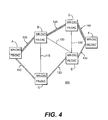
- FIG. 4 illustrates optical network 300, including the switches depicted in FIG. 3, as applied to the arrangement of Nodes A-F from FIG. 1.
- each of Nodes A-F includes both an FR-OXC and a WR-OXC.
- Nodes A, E, and F process substantially more local channels than passthrough channels, and therefore, qualify as hub nodes.
- the switch architectures within these nodes are similar to OXC 305 from FIG. 3.
- FIG. 4 shows the relative switching capacity between the sub-switch portions in nodes A, E and F, where the WR-OXC area is substantially larger than the FR-OXC area. Indeed, in these hub nodes, the FR-OXC may be omitted altogether to increase the switching simplicity if the number of passthrough channels is de minimus.
- the preferred embodiment of the present invention also benefits from decreased material cost.
- the cost of an optical cross-connect switch within a node depends on the technology used for the optical functions, mainly from the type of optical switches used. Moreover, for opaque networks, the cost of the transponders is very important.
- a normalized measure of the OXC cost can be obtained with a simple model. Assume that the switch matrixes have crossbar architecture so as to assure complete connectivity. In this case, the cost of a matrix is approximately proportional to the square of the number of its ports. Therefore, the cost ⁇ SW of the switch fabric of a WR-OXC as shown in FIG.
- ⁇ SW A x M x N 2
- N the number of fibers
- M the number of wavelengths per fiber
- A a scale factor that depends on the technology.
- ⁇ C1 additional features, such as the multiplexer, demultiplexers, electronics, and software has to be added.
- the cost (2 x B x N x M) of the transponders also has to be included, where B is the cost of a transponder.
- ⁇ WR (A x M x N 2 ) + (2 x B x N x M) + ⁇ C1 .
- ⁇ TW (A x M x K 2 ) + (2 x B x K x M) + ⁇ C2
- K equals the number of fibers entering the WR-OXC switch
- ⁇ C2 is the cost of additional features in the WR-OXC.
- ⁇ TF A(N + K) 2 + ⁇ C3 , where ⁇ C3 is a fixed additional cost.
- Node D in network 100 of FIG. 1 the economic advantage of using optical switches with mixed FR-OXC and WR-OXC versus only WR-OXCs becomes apparent.
- This node has nine input and output fibers and one Add/Drop port including four fibers that is able to process up to four wavelength channels.
- the Add/Drop port is equal to an input/output fiber couple, but for the absence of a multiplexer or demultiplexer.
- the overall number of ports of the node D is ten.
- the factor ⁇ is given by The real value of ⁇ depends essentially on the ratio A/B, that is on the technology used for the switch and for the transponders.
- the values of ⁇ vary from a maximum of about 3.3, when the OXC cost is practically determined by the sole transponders, to a minimum of about 2, when the cost is determined only by the switch fabrics. It follows that, in the absence of transmission problems, the maximum advantage is gained when the transponders mainly determine the cost of the OXC.
- transponders are used not only to process the optical channel header but also to correct transmission problems. In this case, even the WDM combs that can be routed as a whole need demultiplexing to be regenerated.
- FIG. 6 shows that an increase of the value of K decreases the advantage derived from the use of the mixed switch having FR-OXC and WR-OXC portions.
- the above considerations, adapted to the case of a specific network, can assist the skilled in the art in determining whether any node within the network can be advantageously implemented with a WR-OXC architecture rather than with a mixed FR-OXC and WR-OXC architecture.
- the greater advantage in using the mixed FR-OXC and WR-OXC architecture is attained when the cost of the OXC is mainly determined by the transponders.
Landscapes
- Engineering & Computer Science (AREA)
- Computer Networks & Wireless Communication (AREA)
- Signal Processing (AREA)
- Optical Communication System (AREA)
- Use Of Switch Circuits For Exchanges And Methods Of Control Of Multiplex Exchanges (AREA)
Priority Applications (3)
| Application Number | Priority Date | Filing Date | Title |
|---|---|---|---|
| EP00111791A EP1162855B1 (de) | 2000-06-05 | 2000-06-05 | Optisches wellenlängenmultiplexiertes System mit kombinierten wellenlängen Leitweglenkung und Leitweglenkung von optischen Fasern |
| DE60028551T DE60028551T2 (de) | 2000-06-05 | 2000-06-05 | Optisches wellenlängenmultiplexiertes System mit kombinierten wellenlängen Leitweglenkung und Leitweglenkung von optischen Fasern |
| US09/800,886 US6792207B2 (en) | 2000-06-05 | 2001-03-08 | Optical WDM network having mixed wavelength routing and fiber routing cross-connect switches |
Applications Claiming Priority (1)
| Application Number | Priority Date | Filing Date | Title |
|---|---|---|---|
| EP00111791A EP1162855B1 (de) | 2000-06-05 | 2000-06-05 | Optisches wellenlängenmultiplexiertes System mit kombinierten wellenlängen Leitweglenkung und Leitweglenkung von optischen Fasern |
Publications (2)
| Publication Number | Publication Date |
|---|---|
| EP1162855A1 true EP1162855A1 (de) | 2001-12-12 |
| EP1162855B1 EP1162855B1 (de) | 2005-12-07 |
Family
ID=8168895
Family Applications (1)
| Application Number | Title | Priority Date | Filing Date |
|---|---|---|---|
| EP00111791A Expired - Lifetime EP1162855B1 (de) | 2000-06-05 | 2000-06-05 | Optisches wellenlängenmultiplexiertes System mit kombinierten wellenlängen Leitweglenkung und Leitweglenkung von optischen Fasern |
Country Status (3)
| Country | Link |
|---|---|
| US (1) | US6792207B2 (de) |
| EP (1) | EP1162855B1 (de) |
| DE (1) | DE60028551T2 (de) |
Cited By (4)
| Publication number | Priority date | Publication date | Assignee | Title |
|---|---|---|---|---|
| EP1207642A3 (de) * | 2000-10-31 | 2002-08-21 | Lucent Technologies Inc. | Verfahren und Vorrichtung zur Beendigung von optischen Verbindungen in einem optischen Netzwerk |
| WO2003081824A1 (de) * | 2002-03-21 | 2003-10-02 | Siemens Aktiengesellschaft | Cross-connector für optische signale |
| EP1379100A1 (de) * | 2002-07-04 | 2004-01-07 | Alcatel | Optischer Kreuzschienenverteiler mit granularer Architektur |
| WO2016045716A1 (en) * | 2014-09-24 | 2016-03-31 | Telefonaktiebolaget L M Ericsson (Publ) | Optical node |
Families Citing this family (28)
| Publication number | Priority date | Publication date | Assignee | Title |
|---|---|---|---|---|
| US6731830B2 (en) * | 2001-01-05 | 2004-05-04 | Redfern Broadband Networks, Inc. | Asymmetric compatible network element |
| CA2441045A1 (en) * | 2001-03-16 | 2002-09-26 | Photuris, Inc. | Method and apparatus for transferring wdm signals between different wdm communications systems in optically transparent manner |
| US7295783B2 (en) | 2001-10-09 | 2007-11-13 | Infinera Corporation | Digital optical network architecture |
| US7155084B2 (en) * | 2002-05-17 | 2006-12-26 | Altera Corporation | Bidirectional wavelength cross connect architectures using wavelength routing elements |
| US7194206B2 (en) * | 2002-05-15 | 2007-03-20 | Altera Corporation | Variable-density optical cross-connect architectures and upgrades |
| US7149433B2 (en) | 2002-06-28 | 2006-12-12 | Infineria Corporation | Upgrade of optical amplifier site to a digital optical network site in an optical transmission network |
| FR2844955B1 (fr) * | 2002-09-19 | 2005-01-14 | Cit Alcatel | Brasseur optique d'architecture multigranulaire |
| US8958697B2 (en) | 2003-06-10 | 2015-02-17 | Alexander I. Soto | System and method for optical layer management in optical modules and remote control of optical modules |
| WO2005019970A2 (en) * | 2003-07-03 | 2005-03-03 | Ubi Systems, Inc. | Communication system and method for an optical local area network |
| JP4642623B2 (ja) * | 2005-09-30 | 2011-03-02 | 富士通株式会社 | 波長分割多重装置 |
| GB0416107D0 (en) * | 2004-07-19 | 2004-08-18 | British Telecomm | Wavelength selection |
| GB0416110D0 (en) * | 2004-07-19 | 2004-08-18 | British Telecomm | Path establishment |
| US7242841B2 (en) * | 2005-02-28 | 2007-07-10 | Corning Cable Systems, Llc | Cross-connect fiber optic cables and associated cross-connect sections |
| US7676155B2 (en) * | 2005-12-08 | 2010-03-09 | Electronics And Telecommunications Research Institute | Dynamic wavelength allocation device using 3R wavelength converter having limited wavelength conversion range and method thereof |
| US8995829B2 (en) * | 2007-06-05 | 2015-03-31 | Cisco Technology, Inc. | Optical link quality monitoring in a computer network |
| KR20110127968A (ko) * | 2010-05-20 | 2011-11-28 | 엘에스산전 주식회사 | R fid를 이용한 원격 제어 송수신 장치 및 그 방법 |
| RU2608300C2 (ru) | 2011-10-28 | 2017-01-17 | Неофотоникс Корпорейшн | Масштабируемые оптические коммутаторы и модули коммутации |
| US9398354B2 (en) * | 2013-02-20 | 2016-07-19 | Xtera Communications, Inc. | Integrated assembly for switching optical signals |
| EP2797247A1 (de) | 2013-04-24 | 2014-10-29 | British Telecommunications Public Limited Company | Optische Datenübertragung |
| JP6342894B2 (ja) * | 2013-06-20 | 2018-06-13 | 国立研究開発法人科学技術振興機構 | 光クロスコネクト装置 |
| US10382158B2 (en) | 2013-10-03 | 2019-08-13 | The Hong Kong Polytechnic University | Reversible wavelength channels for optical communication networks |
| US20150098477A1 (en) * | 2013-10-03 | 2015-04-09 | Versitech Limited | Reversible wavelength channels for optical communication networks |
| WO2015052468A1 (en) | 2013-10-11 | 2015-04-16 | British Telecommunications Public Limited Company | Optical data transmission method and apparatus |
| US9742520B1 (en) | 2014-09-19 | 2017-08-22 | Neophotonics Corporation | Optical switching system with a colorless, directionless, and contentionless ROADM connected to unamplified drop channels |
| CN107431551B (zh) * | 2015-04-13 | 2019-02-05 | 华为技术有限公司 | 光交叉互连节点和光信号交换的方法 |
| JP6877766B2 (ja) * | 2016-03-08 | 2021-05-26 | 国立大学法人東海国立大学機構 | 光クロスコネクト装置 |
| EP3811593A1 (de) | 2018-06-21 | 2021-04-28 | British Telecommunications public limited company | Pfadauswahl für inhaltsbereitstellungsnetzwerk |
| US12355563B2 (en) | 2022-01-24 | 2025-07-08 | Cisco Technology, Inc. | Correlating transceiver parameters for insight into transceiver health |
Citations (2)
| Publication number | Priority date | Publication date | Assignee | Title |
|---|---|---|---|---|
| EP0620694A2 (de) * | 1993-04-16 | 1994-10-19 | Nec Corporation | Optisches Querverbindungssystem mit Raum- und Wellenlängenvermittlungsstufen |
| EP0752794A2 (de) * | 1995-07-05 | 1997-01-08 | Fujitsu Limited | Querverbindungseinrichtung für optische Netzwerke |
Family Cites Families (1)
| Publication number | Priority date | Publication date | Assignee | Title |
|---|---|---|---|---|
| US6160651A (en) * | 1999-01-25 | 2000-12-12 | Telcordia Technologies, Inc. | Optical layer survivability and security system using optical label switching and high-speed optical header reinsertion |
-
2000
- 2000-06-05 DE DE60028551T patent/DE60028551T2/de not_active Expired - Lifetime
- 2000-06-05 EP EP00111791A patent/EP1162855B1/de not_active Expired - Lifetime
-
2001
- 2001-03-08 US US09/800,886 patent/US6792207B2/en not_active Expired - Lifetime
Patent Citations (2)
| Publication number | Priority date | Publication date | Assignee | Title |
|---|---|---|---|---|
| EP0620694A2 (de) * | 1993-04-16 | 1994-10-19 | Nec Corporation | Optisches Querverbindungssystem mit Raum- und Wellenlängenvermittlungsstufen |
| EP0752794A2 (de) * | 1995-07-05 | 1997-01-08 | Fujitsu Limited | Querverbindungseinrichtung für optische Netzwerke |
Non-Patent Citations (1)
| Title |
|---|
| FUJIWARA M: "ADVANCED PHOTONIC SWITCHING TECHNOLOGY FOR COMMUNICATIONS", IEICE TRANSACTIONS ON COMMUNICATIONS,INSTITUTE OF ELECTRONICS INFORMATION AND COMM. ENG. TOKYO,JP, vol. E78-B, no. 5, 1 May 1995 (1995-05-01), pages 644 - 653, XP000513463, ISSN: 0916-8516 * |
Cited By (9)
| Publication number | Priority date | Publication date | Assignee | Title |
|---|---|---|---|---|
| EP1207642A3 (de) * | 2000-10-31 | 2002-08-21 | Lucent Technologies Inc. | Verfahren und Vorrichtung zur Beendigung von optischen Verbindungen in einem optischen Netzwerk |
| US6735390B1 (en) | 2000-10-31 | 2004-05-11 | Lucent Technologies Inc. | Method and apparatus for terminating optical links in an optical network |
| WO2003081824A1 (de) * | 2002-03-21 | 2003-10-02 | Siemens Aktiengesellschaft | Cross-connector für optische signale |
| CN100539491C (zh) * | 2002-03-21 | 2009-09-09 | 诺基亚西门子通信有限责任两合公司 | 用于光信号的十字形联接件 |
| US7702239B2 (en) | 2002-03-21 | 2010-04-20 | Nokia Siemens Networks Gmbh & Co. Kg | Cross-connector for optical signals |
| EP1379100A1 (de) * | 2002-07-04 | 2004-01-07 | Alcatel | Optischer Kreuzschienenverteiler mit granularer Architektur |
| FR2842049A1 (fr) * | 2002-07-04 | 2004-01-09 | Cit Alcatel | Brasseur optique d'architecture multigranulaire |
| WO2016045716A1 (en) * | 2014-09-24 | 2016-03-31 | Telefonaktiebolaget L M Ericsson (Publ) | Optical node |
| US10419148B2 (en) | 2014-09-24 | 2019-09-17 | Telefonaktiebolaget Lm Ericsson (Publ) | Optical node |
Also Published As
| Publication number | Publication date |
|---|---|
| US20020030867A1 (en) | 2002-03-14 |
| US6792207B2 (en) | 2004-09-14 |
| EP1162855B1 (de) | 2005-12-07 |
| DE60028551T2 (de) | 2006-09-28 |
| DE60028551D1 (de) | 2006-07-20 |
Similar Documents
| Publication | Publication Date | Title |
|---|---|---|
| EP1162855B1 (de) | Optisches wellenlängenmultiplexiertes System mit kombinierten wellenlängen Leitweglenkung und Leitweglenkung von optischen Fasern | |
| JP3582030B2 (ja) | クロスコネクト装置 | |
| CA2285128C (en) | Switch for optical signals | |
| US5550818A (en) | System for wavelength division multiplexing/asynchronous transfer mode switching for network communication | |
| US6738540B2 (en) | Optical cross-connect switch using programmable multiplexers/demultiplexers | |
| US7162632B2 (en) | Efficient optical network design using multi-granular optical cross-connects with wavelength band switching | |
| US5878177A (en) | Layered switch architectures for high-capacity optical transport networks | |
| US9258628B2 (en) | Method and apparatus for transferring WDM signals between different wavelength division multiplexed optical communications systems in an optically transparent manner | |
| US7574080B2 (en) | Technique for photonic switching | |
| US9014562B2 (en) | Optical line terminal arrangement, apparatus and methods | |
| JPH0923457A (ja) | 非閉塞型交差接続交換装置 | |
| EP2979383B1 (de) | Optischer schalter | |
| US6496289B1 (en) | Optical exchanger | |
| CN100492957C (zh) | 光信号转换设备、光通信网及它们的使用方法 | |
| EP1043847B1 (de) | Wdm-übertragungsnetzwerkvorrichtung mit sender/empfänger mit optischem schalter mit 2 eingängen und 2 ausgängen | |
| EP1408713A2 (de) | Optisches Querverbindungssystem | |
| US6959128B2 (en) | Coupler-based optical cross-connect having a regeneration module | |
| JP4021585B2 (ja) | 光パスクロスコネクト装置 | |
| KR100431204B1 (ko) | 광스위치 패브릭 모듈을 이용한 대용량 광교차연결 스위칭시스템 | |
| JPH11243564A (ja) | 光クロスコネクト装置 | |
| JPH066844A (ja) | 波長分割多重光クロスコネクトスイッチ装置 | |
| Limal et al. | Optical cross-connect and link dimensioning of a multi-wavelength network with and | |
| CA2426857A1 (en) | Optical communications network and node for forming such a network | |
| Yang | Understanding wavelength cross-connects and their benefits throughout the network |
Legal Events
| Date | Code | Title | Description |
|---|---|---|---|
| PUAI | Public reference made under article 153(3) epc to a published international application that has entered the european phase |
Free format text: ORIGINAL CODE: 0009012 |
|
| AK | Designated contracting states |
Kind code of ref document: A1 Designated state(s): AT BE CH CY DE DK ES FI FR GB GR IE IT LI LU MC NL PT SE Kind code of ref document: A1 Designated state(s): DE FR GB IT NL |
|
| AX | Request for extension of the european patent |
Free format text: AL;LT;LV;MK;RO;SI |
|
| 17P | Request for examination filed |
Effective date: 20020603 |
|
| AKX | Designation fees paid |
Free format text: DE FR GB IT NL |
|
| 17Q | First examination report despatched |
Effective date: 20041013 |
|
| RTI1 | Title (correction) |
Free format text: OPTICAL WDM NETWORK HAVING COMBINED WAVELENGTH ROUTING AND FIBER ROUTING |
|
| GRAP | Despatch of communication of intention to grant a patent |
Free format text: ORIGINAL CODE: EPIDOSNIGR1 |
|
| GRAS | Grant fee paid |
Free format text: ORIGINAL CODE: EPIDOSNIGR3 |
|
| GRAA | (expected) grant |
Free format text: ORIGINAL CODE: 0009210 |
|
| AK | Designated contracting states |
Kind code of ref document: B1 Designated state(s): DE FR GB IT NL |
|
| PG25 | Lapsed in a contracting state [announced via postgrant information from national office to epo] |
Ref country code: IT Free format text: LAPSE BECAUSE OF FAILURE TO SUBMIT A TRANSLATION OF THE DESCRIPTION OR TO PAY THE FEE WITHIN THE PRESCRIBED TIME-LIMIT;WARNING: LAPSES OF ITALIAN PATENTS WITH EFFECTIVE DATE BEFORE 2007 MAY HAVE OCCURRED AT ANY TIME BEFORE 2007. THE CORRECT EFFECTIVE DATE MAY BE DIFFERENT FROM THE ONE RECORDED. Effective date: 20051207 Ref country code: NL Free format text: LAPSE BECAUSE OF FAILURE TO SUBMIT A TRANSLATION OF THE DESCRIPTION OR TO PAY THE FEE WITHIN THE PRESCRIBED TIME-LIMIT Effective date: 20051207 |
|
| REG | Reference to a national code |
Ref country code: GB Ref legal event code: FG4D |
|
| NLV1 | Nl: lapsed or annulled due to failure to fulfill the requirements of art. 29p and 29m of the patents act | ||
| ET | Fr: translation filed | ||
| REF | Corresponds to: |
Ref document number: 60028551 Country of ref document: DE Date of ref document: 20060720 Kind code of ref document: P |
|
| PLBE | No opposition filed within time limit |
Free format text: ORIGINAL CODE: 0009261 |
|
| STAA | Information on the status of an ep patent application or granted ep patent |
Free format text: STATUS: NO OPPOSITION FILED WITHIN TIME LIMIT |
|
| 26N | No opposition filed |
Effective date: 20060908 |
|
| REG | Reference to a national code |
Ref country code: FR Ref legal event code: PLFP Year of fee payment: 17 |
|
| REG | Reference to a national code |
Ref country code: FR Ref legal event code: PLFP Year of fee payment: 18 |
|
| REG | Reference to a national code |
Ref country code: FR Ref legal event code: PLFP Year of fee payment: 19 |
|
| PGFP | Annual fee paid to national office [announced via postgrant information from national office to epo] |
Ref country code: FR Payment date: 20190625 Year of fee payment: 20 |
|
| PGFP | Annual fee paid to national office [announced via postgrant information from national office to epo] |
Ref country code: GB Payment date: 20190627 Year of fee payment: 20 Ref country code: DE Payment date: 20190627 Year of fee payment: 20 |
|
| REG | Reference to a national code |
Ref country code: DE Ref legal event code: R071 Ref document number: 60028551 Country of ref document: DE |
|
| REG | Reference to a national code |
Ref country code: GB Ref legal event code: PE20 Expiry date: 20200604 |
|
| PG25 | Lapsed in a contracting state [announced via postgrant information from national office to epo] |
Ref country code: GB Free format text: LAPSE BECAUSE OF EXPIRATION OF PROTECTION Effective date: 20200604 |