EP1163452B1 - Compresseur a vis - Google Patents
Compresseur a vis Download PDFInfo
- Publication number
- EP1163452B1 EP1163452B1 EP00922512A EP00922512A EP1163452B1 EP 1163452 B1 EP1163452 B1 EP 1163452B1 EP 00922512 A EP00922512 A EP 00922512A EP 00922512 A EP00922512 A EP 00922512A EP 1163452 B1 EP1163452 B1 EP 1163452B1
- Authority
- EP
- European Patent Office
- Prior art keywords
- housing
- rotor
- rotor housing
- rotors
- gear
- Prior art date
- Legal status (The legal status is an assumption and is not a legal conclusion. Google has not performed a legal analysis and makes no representation as to the accuracy of the status listed.)
- Expired - Lifetime
Links
Images


Classifications
-
- F—MECHANICAL ENGINEERING; LIGHTING; HEATING; WEAPONS; BLASTING
- F04—POSITIVE - DISPLACEMENT MACHINES FOR LIQUIDS; PUMPS FOR LIQUIDS OR ELASTIC FLUIDS
- F04C—ROTARY-PISTON, OR OSCILLATING-PISTON, POSITIVE-DISPLACEMENT MACHINES FOR LIQUIDS; ROTARY-PISTON, OR OSCILLATING-PISTON, POSITIVE-DISPLACEMENT PUMPS
- F04C29/00—Component parts, details or accessories of pumps or pumping installations, not provided for in groups F04C18/00 - F04C28/00
- F04C29/02—Lubrication; Lubricant separation
- F04C29/025—Lubrication; Lubricant separation using a lubricant pump
-
- F—MECHANICAL ENGINEERING; LIGHTING; HEATING; WEAPONS; BLASTING
- F04—POSITIVE - DISPLACEMENT MACHINES FOR LIQUIDS; PUMPS FOR LIQUIDS OR ELASTIC FLUIDS
- F04C—ROTARY-PISTON, OR OSCILLATING-PISTON, POSITIVE-DISPLACEMENT MACHINES FOR LIQUIDS; ROTARY-PISTON, OR OSCILLATING-PISTON, POSITIVE-DISPLACEMENT PUMPS
- F04C23/00—Combinations of two or more pumps, each being of rotary-piston or oscillating-piston type, specially adapted for elastic fluids; Pumping installations specially adapted for elastic fluids; Multi-stage pumps specially adapted for elastic fluids
-
- F—MECHANICAL ENGINEERING; LIGHTING; HEATING; WEAPONS; BLASTING
- F04—POSITIVE - DISPLACEMENT MACHINES FOR LIQUIDS; PUMPS FOR LIQUIDS OR ELASTIC FLUIDS
- F04C—ROTARY-PISTON, OR OSCILLATING-PISTON, POSITIVE-DISPLACEMENT MACHINES FOR LIQUIDS; ROTARY-PISTON, OR OSCILLATING-PISTON, POSITIVE-DISPLACEMENT PUMPS
- F04C27/00—Sealing arrangements in rotary-piston pumps specially adapted for elastic fluids
- F04C27/008—Sealing arrangements in rotary-piston pumps specially adapted for elastic fluids for other than working fluid, i.e. the sealing arrangements are not between working chambers of the machine
- F04C27/009—Shaft sealings specially adapted for pumps
-
- F—MECHANICAL ENGINEERING; LIGHTING; HEATING; WEAPONS; BLASTING
- F04—POSITIVE - DISPLACEMENT MACHINES FOR LIQUIDS; PUMPS FOR LIQUIDS OR ELASTIC FLUIDS
- F04C—ROTARY-PISTON, OR OSCILLATING-PISTON, POSITIVE-DISPLACEMENT MACHINES FOR LIQUIDS; ROTARY-PISTON, OR OSCILLATING-PISTON, POSITIVE-DISPLACEMENT PUMPS
- F04C18/00—Rotary-piston pumps specially adapted for elastic fluids
- F04C18/08—Rotary-piston pumps specially adapted for elastic fluids of intermeshing-engagement type, i.e. with engagement of co-operating members similar to that of toothed gearing
- F04C18/12—Rotary-piston pumps specially adapted for elastic fluids of intermeshing-engagement type, i.e. with engagement of co-operating members similar to that of toothed gearing of other than internal-axis type
- F04C18/14—Rotary-piston pumps specially adapted for elastic fluids of intermeshing-engagement type, i.e. with engagement of co-operating members similar to that of toothed gearing of other than internal-axis type with toothed rotary pistons
- F04C18/16—Rotary-piston pumps specially adapted for elastic fluids of intermeshing-engagement type, i.e. with engagement of co-operating members similar to that of toothed gearing of other than internal-axis type with toothed rotary pistons with helical teeth, e.g. chevron-shaped, screw type
-
- F—MECHANICAL ENGINEERING; LIGHTING; HEATING; WEAPONS; BLASTING
- F04—POSITIVE - DISPLACEMENT MACHINES FOR LIQUIDS; PUMPS FOR LIQUIDS OR ELASTIC FLUIDS
- F04C—ROTARY-PISTON, OR OSCILLATING-PISTON, POSITIVE-DISPLACEMENT MACHINES FOR LIQUIDS; ROTARY-PISTON, OR OSCILLATING-PISTON, POSITIVE-DISPLACEMENT PUMPS
- F04C2240/00—Components
- F04C2240/60—Shafts
- F04C2240/605—Shaft sleeves or details thereof
Definitions
- the invention relates to a screw compressor in the Preamble of claim 1 mentioned type.
- the invention is preferred, but not exclusively applicable to a screw compressor for generating a compressed air flow for the pneumatic transport of bulk goods, and especially one for attachment to one Silo vehicle trained screw processor.
- Screw compressors work on the displacement principle Air compressors compared to other types of compressors have beneficial properties they especially for the pneumatic transport of bulk goods make suitable. This applies in particular to so-called dry running screw compressors, where the by a synchronous gear synchronized screw rotors no contact with each other and with the surrounding housing parts to have. There is therefore no one in the compression room Lubrication is required so that they are kept oil-free can and therefore any contamination of the compressed air is avoided with oil. Due to the non-contact running of the Rotors are also not subject to wear in this area instead, which reduces the lifespan, and there is no Abrasion that can contaminate the transported air.
- Screw compressors are due to their operating characteristics especially for realizing high pressure ratios suitable and are insensitive to short-term Pressure increases caused by clogging with the compressed air loaded pipeline could be caused. Finally, they are lighter in weight and smaller in size, what they are especially for mobile use z. B. makes suitable for silo vehicles.
- the invention has for its object the mouth of one from the pressure side storage area the ventilation duct leading out of the rotors, particularly protected.
- the housing of the compressor shown in Figs. 1-4 is composed of the following main parts: one Gear housing 1, a rotor housing 3, an inflow housing 4, a suction housing 5 and an oil tank 7.
- the rotor housing 3 are two rotors, namely a main rotor 9 (profile teeth) and a secondary runner 11 (profile gaps) rotatably mounted with their helical Interlock teeth and tooth gaps while sealing Form chambers, which are in the rotation of the rotor Move and reduce the axial direction and thereby the suctioned Compress air.
- the rotors so driven that the right end in Figs. 1-3 Suction side is.
- air gets through at the front of the Rotor housing 3 provided intake openings 13 sucked.
- the air is from the interlocking teeth and Tooth gaps of the rotor pair in the axial direction to the left promoted and occurs as compressed air on the pressure side End of the rotors at an upward pressure outlet 15 out.
- the principle of operation of a screw compressor is known and will not be explained here.
- the gear housing 1 has the shape of a disk-like Stand. In it, the drive shaft 17 is in bearings 16, 18 of the compressor, whose from the housing cover 49th protruding shaft journal 17a to a not shown Rotary drive is connected.
- the gearbox 1 also contains a drive gear consisting of a on the drive shaft 17 fixed gear 19 and a fastened on the shaft journal 23 of the secondary rotor 11 Gear 21 through which the rotation of the drive shaft 17th with a suitable gear ratio to the secondary runner 11 is transmitted. Furthermore, in the gear housing 1, d. H.
- the overall stator or disc-shaped gear housing 1 has on both sides at its lower base cantilevered mounting feet 31 with holes 33 for Fastening screws that secure the entire compressor a suitable pad, e.g. B. a vehicle attached can be.
- the rotor housing 3 on the gear housing 1 by means of a flange connection 37 attached so that it projects freely from the gear housing 1.
- the oil container 7, which has a flat box shape, is also attached to the gear housing 1 so that it is free of this cantilevered, approximately parallel to the rotor housing 3 and below it.
- the side walls of the oil container 7 are provided with cooling fins 39.
- Between the oil tank 7 and the bottom of the rotor housing 3 is a relatively wide air gap 41.
- an oil pump 45 For the circulation of the oil inside the gearbox 1, or for generating an oil mist, an oil pump 45 is used, which surrounds and is driven by the drive shaft 17 becomes.
- the housing of the oil pump 45 has a protruding outward Flange 47, which is used to center the gearbox housing 1 attached housing cover 49 is used.
- the oil pump 45 is with 4 screws 51 (Fig. 3) and associated threaded holes attached to the gear housing 1.
- the inlet openings that close the rotor housing 3 on the suction side 13 inflow housing 4 is at a distance surrounded by a large-volume intake housing 5 (in Fig. 2 and Fig. 3 only indicated by dash-dotted lines), the means Screws attached to a flange 67 of the rotor housing 3 is.
- Intake housing 5 is an intake filter for filtering the intake air and / or a damper Soundproofing.
- the suction housing 5 contains a filter 6 from a suitable one porous or air-permeable filter material.
- the Filter lies in an air flow path between an outer one Suction slot 69 and one in an inner partition 71 arranged passage slot 73, with suction slot 69 and passage slot are offset so that a longest possible flow path for the air between the Slits 69, 73 is formed by the filter 6.
- Intake housing 5 is a modified embodiment of the intake housing 5, in which the through the suction slot 69 sucked in and through the deflection wall 71 Passage slot 73 redirects air e.g. from suitable Flows through perforated plates trained muffler 75, before entering the space surrounding the housing cover 69 arrives and through the inflow openings 13 into the interior of the rotor housing 3 flows. It is also possible that Intake housing 5 so that it is both a filter as well as a silencer.
- An advantage of the direct attachment of a filter and / or a silencer-containing suction housing 5 on the rotor housing 3 such that it is the inflow housing 4 at a distance surrounds is that a separate arrangement of a Filters and / or silencers, and a connecting line between this and the suction side of the compressor can. This makes it particularly simple, compact and robust arrangement achieved.
- Another advantage is there in that the air sucked into the suction housing 5 Outside of the inflow housing containing the shaft journal bearings 4 flows around and cools before passing through the Inflow openings 13 enters the interior of the rotor housing 3. This ensures effective cooling of the suction side Rotor bearing achieved.
- Fig. 6 shows the storage in an enlarged sectional view and sealing the shaft journal 55 of the rotor 9 in the inflow housing 4.
- the shaft journal 57 of the other rotor 11 is mounted and sealed in an analogous manner.
- the shaft journals provided with tool engagement (flats 63) 57 is formed in the manner of a hub Middle part of the inflow housing 4 by means of a roller bearing 53 stored between a shoulder of the shaft journal 57 and one engaging in an annular groove of the shaft journal Circlip 83 is arranged. Because on the suction side the rotors 9, 11, as stated above, no oil lubrication Rolling bearing 53 is preferably to take place as an encapsulated bearing with a lifetime grease filling trained so that there is no subsequent lubrication needed.
- the race 85 which e.g. a commercial one
- the race for a rolling bearing can consist of Steel with a specially hardened peripheral surface.
- the inner shoulder 4a of the inflow housing 4 has a protective ring 89 arranged, the inner circumference of the outer surface of the Race 85 with a very small gap, but without contact faces.
- the protective ring 89 and the lip seal 87 are against each other and on the inner shoulder 4a of the inflow housing 4 in the bore of the housing fixed, preferably glued.
- the function of the guard ring 89 is as follows:
- the compressor generated during operation by sucking in air on the Suction side and blowing out compressed air at the pressure port 15 a compressed air flow, e.g. for pneumatic transport of dusty goods can serve.
- a compressed air flow e.g. for pneumatic transport of dusty goods
- the guard ring protects 89 the lip seal 87 in front of that dust particles underneath the sealing lips of the lip seal ring 87 and impair the sealing effect.
- suction-side bearing arrangement has the further advantage that it can be withdrawn from the shaft journal 57 without the rotor 9 or 11 removed or the precise setting the rotors must be changed to each other.
- the Remove the bearing and seal assembly from the journal can be done in the following ways:
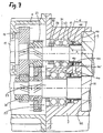
- FIG. 7 shows in a sectional view corresponding to FIG. 3, but on a larger scale the storage and sealing of the pressure side shaft journal 29, 23 of the rotors 9, 11 am pressure-side end of the rotor housing 3.
- the one for the shaft journal 23 the rotor 11 is completely analog.
- the shaft journal 29 is in the pressure-side end wall of the Rotor housing 3 by two roller bearings arranged side by side 91, 93 stored, the so-called angular contact ball bearings are trained.
- Angular contact ball bearings that are commercially available are ball bearings, the balls of which are from the outside and inner race only on one or the other side of the radial central plane are encompassed.
- the two angular contact ball bearings 91, 93 are arranged side by side in mirror symmetry. Such an arrangement of angular contact ball bearings has the Property that it is completely free of play in the axial direction.
- a shaft nut 95 arranged on the shaft journal 29 puts the angular contact ball bearings 91, 93 in the axial direction on the Shaft journal 29 firmly.
- the outer race of the angular contact ball bearing 93 lies against an inner shoulder 97 of the rotor housing 3 on.
- Race 101 is located between the angular contact ball bearing 93 and the rotor 9 a section of the shaft journal 29 on which a Race 101 attached, preferably shrunk.
- This race 101 is made just like the one previously described 6, made of steel with a special hardened peripheral surface.
- the hardened and extremely precisely machined, e.g. polished Outer surface of the race 25 results in a particularly wear-reducing Contact surface for the sealing lips of the lip sealing ring 103rd
- labyrinth sealing ring 105 on its inner circumference has several adjacent ring ribs, that of the outer surface of the race 101 with very little Face the gap, but without contact and with this form a labyrinth gap.
- the race 101 normally no contact with the labyrinth sealing ring 105 , it is still advantageous that the Race 101 also over the area of the labyrinth seal 105 extends.
- the labyrinth gap seal is normal a non-contact seal, but it can be under extreme operating conditions under certain circumstances between the ring ribs of the labyrinth sealing ring 105 and the Race 101 take place.
- race 101 If the race 101 is not would be present, there would be grooves on the shaft journal 29 are generated so that it is damaged and the Rotor 9 becomes unusable. Thanks to the presence of the race In such a case 101, only the race 101 needs to be replaced to be so that the rotor 9, otherwise Damage free, can be used again.
- FIG. 4 shows a perspective view from below of the Compressor with the oil container 7 removed, so that in the End wall of the gear housing 1, the screw holes 44 for the attachment of the oil tank 7 and the large connection opening 43, through which the oil tank with the gearbox communicated, are visible. Furthermore, in FIG. 4 the suction housing 5 from the suction end of the rotor housing 3 removed, so that the view is clear on the inflow housing 4 with its support ribs 14 and the inside of the Rotor housing 3 leading inflow openings 13. FIG. 4 also indicates the mouth of the lantern (ventilation duct) 109 the underside of the rotor housing 3. As can be seen from FIG.
- the race 101 attached to the shaft journal 29 additionally serves as a spacing element, which is used to maintain a very precisely dimensioned gap between the pressure-side end face of the rotor 9 or 11 and the end face 113 of the rotor housing 3 facing it serves.
- a spacing element which is used to maintain a very precisely dimensioned gap between the pressure-side end face of the rotor 9 or 11 and the end face 113 of the rotor housing 3 facing it serves.
- this gap is set and maintained precisely in such a way that, when the rotor housing 3 is machined, the distance a between the end face 113 facing the rotor 9 and the contact shoulder 97 for the roller bearing 93 is manufactured with very narrow tolerances to a predetermined value ,
- the length b of the race 101, which is used as a spacing element between the roller bearing 97 and the end face of the rotor 9, is also ground with correspondingly precise tolerances to a value which has an oversize compared to the distance a , which is exactly the width of the between Corresponds to rotor 9 and the rotor housing 3 gap to be set.
Landscapes
- Engineering & Computer Science (AREA)
- Mechanical Engineering (AREA)
- General Engineering & Computer Science (AREA)
- Applications Or Details Of Rotary Compressors (AREA)
- Supercharger (AREA)
Claims (4)
- Compresseur à vis comportant deux rotors montés avec leurs axes parallèles dans un carter de rotor (3), lesquels s'engagent l'un dans l'autre par des dents et entredents en forme de vis et qui, pendant le fonctionnement, refoulent de l'air depuis une extrémité côté aspiration en direction d'une extrémité côté refoulement du carter de rotor (3), et le compriment ainsi, comportant un carter de transmission (1) disposé à une extrémité du carter de rotor (3), dans lequel est monté un arbre d'entraínement (17) avec transmission d'entraínement (19, 21) pour les rotors (9, 11), et dans lequel est prévue une lubrification à huile de la transmission d'entraínement et comportant un mécanisme de synchronisation (25, 27) couplant les rotors (9, 11) pour une synchronisation sans contact et en sens contraire, le carter de transmission (1) ayant la forme d'un stator en forme de disque et étant pourvu de moyens (31, 33) pour sa fixation sur un support, le carter de rotor (3) dépassant librement en porte-à-faux du carter de transmission (1), et un réservoir d'huile (7), communiquant avec le carter de transmission (1), dépassant librement en porte-à-faux du carter de transmission (1), sensiblement parallèlement au carter de rotor (3), une fente d'air (41), provoquant une séparation thermique, se trouvant entre le carter de rotor (3) et le réservoir d'huile (7), et dans un dispositif d'étanchéité (103, 105), assurant l'étanchéité des tourillons des arbres (23, 29) côté refoulement des rotors (9, 11) dans le carter de rotor (3), étant prévue une chambre de décharge (107) qui communique avec l'atmosphère par un canal de purge d'air (109) réalisé dans le carter de rotor (3), caractérisé en ce que le canal de purge d'air (109) débouche sur la face du carter de rotor (3) tournée vers le réservoir d'huile (7), de sorte qu'il est protégé d'un accès direct par le réservoir d'huile (7) placé devant.
- Compresseur à vis selon la revendication 1, caractérisé en ce que le réservoir d'huile (7) est pourvu sur ses faces extérieures d'ailettes de refroidissement (39).
- Compresseur à vis selon la revendication 1, caractérisé en ce que sur le carter de rotor (3), des deux côtés de l'embouchure du canal de purge d'air (109), sont réalisées des saillies (111) qui protègent l'embouchure du canal de purge d'air (109) contre un accès depuis le côté.
- Compresseur à vis selon l'une des revendications 1 à 3, caractérisé en ce que le carter de transmission (1) est fermé, sur le côté tourné à l'opposé du carter de rotor (3), par un couvercle de carter (49) qui contient un palier (16) pour l'arbre d'entraínement (17), et en ce que dans le carter de transmission (1) est prévue une pompe à huile (45) servant à la mise en circulation et/ou à la pulvérisation d'huile de lubrification, laquelle comporte une bride annulaire (47) dépassant vers l'extérieur, qui sert au centrage du couvercle de carter (49).
Applications Claiming Priority (3)
| Application Number | Priority Date | Filing Date | Title |
|---|---|---|---|
| DE29904409U | 1999-03-10 | ||
| DE29904409U DE29904409U1 (de) | 1999-03-10 | 1999-03-10 | Schraubenkompressor |
| PCT/EP2000/002151 WO2000053932A1 (fr) | 1999-03-10 | 2000-03-10 | Compresseur a vis |
Publications (2)
| Publication Number | Publication Date |
|---|---|
| EP1163452A1 EP1163452A1 (fr) | 2001-12-19 |
| EP1163452B1 true EP1163452B1 (fr) | 2004-05-19 |
Family
ID=8070664
Family Applications (1)
| Application Number | Title | Priority Date | Filing Date |
|---|---|---|---|
| EP00922512A Expired - Lifetime EP1163452B1 (fr) | 1999-03-10 | 2000-03-10 | Compresseur a vis |
Country Status (5)
| Country | Link |
|---|---|
| US (1) | US6416302B1 (fr) |
| EP (1) | EP1163452B1 (fr) |
| AT (1) | ATE267344T1 (fr) |
| DE (2) | DE29904409U1 (fr) |
| WO (1) | WO2000053932A1 (fr) |
Families Citing this family (27)
| Publication number | Priority date | Publication date | Assignee | Title |
|---|---|---|---|---|
| EP1430124B1 (fr) * | 2000-09-20 | 2013-11-06 | EMD Millipore Corporation | Elements artificiels ubiquistes d'ouverture de la chromatine (ucoe) |
| JP3796210B2 (ja) * | 2002-11-01 | 2006-07-12 | 株式会社神戸製鋼所 | スクリュ圧縮機 |
| US6858067B2 (en) * | 2002-11-12 | 2005-02-22 | Perry Equipment Corporation | Filtration vessel and method for rotary gas compressor system |
| JP4673136B2 (ja) * | 2005-06-09 | 2011-04-20 | 株式会社日立産機システム | スクリュー圧縮機 |
| US8342829B2 (en) * | 2005-12-08 | 2013-01-01 | Ghh Rand Schraubenkompressoren Gmbh | Three-stage screw compressor |
| WO2007065484A1 (fr) * | 2005-12-08 | 2007-06-14 | Ghh Rand Schraubenkompressoren Gmbh | Compresseur à vis |
| JP2008121479A (ja) * | 2006-11-10 | 2008-05-29 | Hitachi Appliances Inc | 密閉形スクリュー圧縮機 |
| US20090129956A1 (en) * | 2007-11-21 | 2009-05-21 | Jean-Louis Picouet | Compressor System and Method of Lubricating the Compressor System |
| JP2009162129A (ja) * | 2008-01-08 | 2009-07-23 | Kobe Steel Ltd | スクリュ圧縮機 |
| US8162625B1 (en) * | 2009-09-22 | 2012-04-24 | Harry Soderstrom | Nested motor, reduction motor reduction gear and pump with selectable mounting options |
| US9267504B2 (en) | 2010-08-30 | 2016-02-23 | Hicor Technologies, Inc. | Compressor with liquid injection cooling |
| US8794941B2 (en) | 2010-08-30 | 2014-08-05 | Oscomp Systems Inc. | Compressor with liquid injection cooling |
| WO2012039715A1 (fr) * | 2010-09-23 | 2012-03-29 | Ingersoll-Rand Company | Silencieux de refoulement modulaire destiné à un compresseur monté sur véhicule |
| CN106640639B (zh) * | 2015-10-29 | 2018-07-06 | 复盛股份有限公司 | 变段式压缩机 |
| US10451061B2 (en) | 2016-05-06 | 2019-10-22 | Ingersoll-Rand Company | Compressor having non-contact and contact seals |
| SG11201810008QA (en) | 2016-05-12 | 2018-12-28 | Golden Renewable Energy Llc | Cyclonic condensing and cooling system |
| US10436525B2 (en) | 2016-05-12 | 2019-10-08 | Golden Renewable Energy, LLC | Cyclonic cooling system |
| US10961062B2 (en) | 2016-06-21 | 2021-03-30 | Golden Renewable Energy, LLC | Bag press feeder assembly |
| IL263806B (en) | 2016-06-21 | 2022-09-01 | Braven Env Llc | System and method for coal separation |
| US20170361268A1 (en) | 2016-06-21 | 2017-12-21 | Golden Renewable Energy | Char separator |
| MX2018015964A (es) | 2016-07-05 | 2019-05-16 | Golden Renewable Energy Llc | Sistema y proceso para convertir plastico de desecho en combustible. |
| US10233393B2 (en) | 2016-07-08 | 2019-03-19 | Golden Renewable Energy, LLC | Heated airlock feeder unit |
| EP3382203B1 (fr) | 2017-03-30 | 2024-05-15 | Roper Pump Company LLC | Pompe à cavité progressive avec gaine de chauffage intégrée |
| CN109915365B (zh) * | 2019-04-04 | 2023-11-17 | 烟台东德氢能技术有限公司 | 罗茨式空气压缩机 |
| BE1030612B1 (nl) * | 2022-06-09 | 2024-01-15 | Atlas Copco Airpower Nv | Behuizing voor het onderbrengen van een tandwielkast van een schroefcompressor |
| WO2023237955A1 (fr) * | 2022-06-09 | 2023-12-14 | Atlas Copco Airpower, Naamloze Vennootschap | Boîtier pour loger une boîte de vitesses d'un compresseur à vis rotatif |
| CN118669328B (zh) * | 2024-08-19 | 2024-12-20 | 常州中变电气有限公司 | 一种双绕组防雷干式变压器用油泵 |
Family Cites Families (9)
| Publication number | Priority date | Publication date | Assignee | Title |
|---|---|---|---|---|
| US3016184A (en) * | 1959-01-19 | 1962-01-09 | Scaife Company | Rotary compressors |
| FR1528285A (fr) * | 1966-06-22 | 1968-06-07 | Atlas Copco Ab | Groupe de compression à compresseurs à rotors hélicoïdaux |
| US3407996A (en) | 1966-06-22 | 1968-10-29 | Atlas Copco Ab | Screw compressor units |
| JPS6293491A (ja) * | 1985-10-21 | 1987-04-28 | Hitachi Ltd | スクリユ−圧縮機 |
| JP2511870B2 (ja) * | 1986-03-20 | 1996-07-03 | 株式会社日立製作所 | スクリユ−真空ポンプ装置 |
| JPH08189483A (ja) * | 1995-01-06 | 1996-07-23 | Tochigi Fuji Ind Co Ltd | コンプレッサ |
| US5772418A (en) * | 1995-04-07 | 1998-06-30 | Tochigi Fuji Sangyo Kabushiki Kaisha | Screw type compressor rotor, rotor casting core and method of manufacturing the rotor |
| US5795136A (en) * | 1995-12-04 | 1998-08-18 | Sundstrand Corporation | Encapsulated rotary screw air compressor |
| DE29807796U1 (de) * | 1998-04-30 | 1999-09-09 | GHH-RAND Schraubenkompressoren GmbH & Co. KG, 46145 Oberhausen | Dichtungsanordnung für einen Wellenzapfen eines trockenlaufenden Rotationsschraubenverdichters |
-
1999
- 1999-03-10 DE DE29904409U patent/DE29904409U1/de not_active Expired - Lifetime
-
2000
- 2000-03-10 DE DE50006496T patent/DE50006496D1/de not_active Expired - Lifetime
- 2000-03-10 AT AT00922512T patent/ATE267344T1/de not_active IP Right Cessation
- 2000-03-10 WO PCT/EP2000/002151 patent/WO2000053932A1/fr not_active Ceased
- 2000-03-10 EP EP00922512A patent/EP1163452B1/fr not_active Expired - Lifetime
-
2001
- 2001-09-10 US US09/950,322 patent/US6416302B1/en not_active Expired - Fee Related
Also Published As
| Publication number | Publication date |
|---|---|
| DE29904409U1 (de) | 2000-07-20 |
| US20020048523A1 (en) | 2002-04-25 |
| US6416302B1 (en) | 2002-07-09 |
| WO2000053932A1 (fr) | 2000-09-14 |
| ATE267344T1 (de) | 2004-06-15 |
| DE50006496D1 (de) | 2004-06-24 |
| EP1163452A1 (fr) | 2001-12-19 |
Similar Documents
| Publication | Publication Date | Title |
|---|---|---|
| EP1163452B1 (fr) | Compresseur a vis | |
| EP1163451B1 (fr) | Compresseur a vis | |
| EP0834017B1 (fr) | Pompe a vide | |
| EP0834018B2 (fr) | Procedé pour refroidir un compresseur à plusieurs étages et à broche hélicoidale | |
| EP0409287B1 (fr) | Pompe à vide avec espace de déplacement | |
| DE69614225T2 (de) | Abdichtung eines brennkraftmaschinen getriebenen Laders | |
| EP0156951A2 (fr) | Pompe à vide avec deux arbres et avec obtention du vide de l'espace d'engrenage | |
| WO2000012899A1 (fr) | Pompe a broche helicoidale a compression a sec | |
| DE19513380C2 (de) | Abdichtung, Lagerung und Antrieb der Rotoren eines trockenlaufenden Schraubenrotorverdichters | |
| EP0408791A1 (fr) | Pompe à effet visqueux à rotor en forme de cloche | |
| DE29904411U1 (de) | Schraubenkompressor | |
| DE19522559A1 (de) | Verdichter mit axialer Förderrichtung, insbesondere in Schraubenspindel-Bauweise | |
| DE19522560A1 (de) | Vakuumpumpe mit einem Paar innerhalb eines axial durchströmten Schöpfraums umlaufender Verdrängerrotoren | |
| EP0569424B1 (fr) | Pompe a vide du type a marche a sec | |
| DE4201486A1 (de) | Oelfreie schraubenkompressoranlage | |
| EP0287797B1 (fr) | Pompe à vide à deux arbres munie d'une transmission de synchronisation | |
| DE20302989U1 (de) | Drehkolbenpumpe | |
| DE202015007606U1 (de) | Trockenvakuumpumpe | |
| EP1770281B1 (fr) | Compresseur pour fluide réfrigérant | |
| DE102009019418A1 (de) | Umlaufverdrängerpumpe mit verbesserter Lagerschmierung | |
| DE19809957A1 (de) | Mehrwellenvakuumpumpe | |
| DE19522551A1 (de) | Zweiwellen-Verdrängermaschine | |
| DE19522555A1 (de) | Rotationskolbenverdichter mit zwei Rotoren | |
| DE19849237A1 (de) | Dichtsystem für eine aus Motor und Getriebe bestehende Antriebseinheit | |
| DE3111834A1 (de) | Schraubenverdichter |
Legal Events
| Date | Code | Title | Description |
|---|---|---|---|
| PUAI | Public reference made under article 153(3) epc to a published international application that has entered the european phase |
Free format text: ORIGINAL CODE: 0009012 |
|
| 17P | Request for examination filed |
Effective date: 20011010 |
|
| AK | Designated contracting states |
Kind code of ref document: A1 Designated state(s): AT BE CH CY DE DK ES FI FR GB GR IE IT LI LU MC NL PT SE |
|
| 17Q | First examination report despatched |
Effective date: 20030314 |
|
| GRAP | Despatch of communication of intention to grant a patent |
Free format text: ORIGINAL CODE: EPIDOSNIGR1 |
|
| GRAS | Grant fee paid |
Free format text: ORIGINAL CODE: EPIDOSNIGR3 |
|
| GRAA | (expected) grant |
Free format text: ORIGINAL CODE: 0009210 |
|
| AK | Designated contracting states |
Kind code of ref document: B1 Designated state(s): AT BE CH CY DE DK ES FI FR GB GR IE IT LI LU MC NL PT SE |
|
| PG25 | Lapsed in a contracting state [announced via postgrant information from national office to epo] |
Ref country code: NL Free format text: LAPSE BECAUSE OF FAILURE TO SUBMIT A TRANSLATION OF THE DESCRIPTION OR TO PAY THE FEE WITHIN THE PRESCRIBED TIME-LIMIT Effective date: 20040519 Ref country code: IE Free format text: LAPSE BECAUSE OF FAILURE TO SUBMIT A TRANSLATION OF THE DESCRIPTION OR TO PAY THE FEE WITHIN THE PRESCRIBED TIME-LIMIT Effective date: 20040519 Ref country code: FI Free format text: LAPSE BECAUSE OF FAILURE TO SUBMIT A TRANSLATION OF THE DESCRIPTION OR TO PAY THE FEE WITHIN THE PRESCRIBED TIME-LIMIT Effective date: 20040519 |
|
| REG | Reference to a national code |
Ref country code: GB Ref legal event code: FG4D Free format text: NOT ENGLISH |
|
| REG | Reference to a national code |
Ref country code: CH Ref legal event code: EP |
|
| REG | Reference to a national code |
Ref country code: IE Ref legal event code: FG4D Free format text: GERMAN |
|
| REF | Corresponds to: |
Ref document number: 50006496 Country of ref document: DE Date of ref document: 20040624 Kind code of ref document: P |
|
| PG25 | Lapsed in a contracting state [announced via postgrant information from national office to epo] |
Ref country code: GR Free format text: LAPSE BECAUSE OF FAILURE TO SUBMIT A TRANSLATION OF THE DESCRIPTION OR TO PAY THE FEE WITHIN THE PRESCRIBED TIME-LIMIT Effective date: 20040819 Ref country code: DK Free format text: LAPSE BECAUSE OF FAILURE TO SUBMIT A TRANSLATION OF THE DESCRIPTION OR TO PAY THE FEE WITHIN THE PRESCRIBED TIME-LIMIT Effective date: 20040819 Ref country code: SE Free format text: LAPSE BECAUSE OF FAILURE TO SUBMIT A TRANSLATION OF THE DESCRIPTION OR TO PAY THE FEE WITHIN THE PRESCRIBED TIME-LIMIT Effective date: 20040819 |
|
| PG25 | Lapsed in a contracting state [announced via postgrant information from national office to epo] |
Ref country code: ES Free format text: LAPSE BECAUSE OF FAILURE TO SUBMIT A TRANSLATION OF THE DESCRIPTION OR TO PAY THE FEE WITHIN THE PRESCRIBED TIME-LIMIT Effective date: 20040830 |
|
| GBT | Gb: translation of ep patent filed (gb section 77(6)(a)/1977) |
Effective date: 20040825 |
|
| NLV1 | Nl: lapsed or annulled due to failure to fulfill the requirements of art. 29p and 29m of the patents act | ||
| ET | Fr: translation filed | ||
| REG | Reference to a national code |
Ref country code: IE Ref legal event code: FD4D |
|
| PG25 | Lapsed in a contracting state [announced via postgrant information from national office to epo] |
Ref country code: AT Free format text: LAPSE BECAUSE OF NON-PAYMENT OF DUE FEES Effective date: 20050310 Ref country code: CY Free format text: LAPSE BECAUSE OF FAILURE TO SUBMIT A TRANSLATION OF THE DESCRIPTION OR TO PAY THE FEE WITHIN THE PRESCRIBED TIME-LIMIT Effective date: 20050310 Ref country code: LU Free format text: LAPSE BECAUSE OF NON-PAYMENT OF DUE FEES Effective date: 20050310 |
|
| PLBE | No opposition filed within time limit |
Free format text: ORIGINAL CODE: 0009261 |
|
| STAA | Information on the status of an ep patent application or granted ep patent |
Free format text: STATUS: NO OPPOSITION FILED WITHIN TIME LIMIT |
|
| PG25 | Lapsed in a contracting state [announced via postgrant information from national office to epo] |
Ref country code: LI Free format text: LAPSE BECAUSE OF NON-PAYMENT OF DUE FEES Effective date: 20050331 Ref country code: CH Free format text: LAPSE BECAUSE OF NON-PAYMENT OF DUE FEES Effective date: 20050331 Ref country code: MC Free format text: LAPSE BECAUSE OF NON-PAYMENT OF DUE FEES Effective date: 20050331 Ref country code: BE Free format text: LAPSE BECAUSE OF NON-PAYMENT OF DUE FEES Effective date: 20050331 |
|
| 26N | No opposition filed |
Effective date: 20050222 |
|
| BERE | Be: lapsed |
Owner name: *GHH-RAND SCHRAUBENKOMPRESSOREN G.M.B.H. Effective date: 20050331 |
|
| REG | Reference to a national code |
Ref country code: CH Ref legal event code: PL |
|
| BERE | Be: lapsed |
Owner name: *GHH-RAND SCHRAUBENKOMPRESSOREN G.M.B.H. Effective date: 20050331 |
|
| PG25 | Lapsed in a contracting state [announced via postgrant information from national office to epo] |
Ref country code: PT Free format text: LAPSE BECAUSE OF NON-PAYMENT OF DUE FEES Effective date: 20041019 |
|
| PGFP | Annual fee paid to national office [announced via postgrant information from national office to epo] |
Ref country code: IT Payment date: 20120326 Year of fee payment: 13 |
|
| PGFP | Annual fee paid to national office [announced via postgrant information from national office to epo] |
Ref country code: DE Payment date: 20130221 Year of fee payment: 14 |
|
| PGFP | Annual fee paid to national office [announced via postgrant information from national office to epo] |
Ref country code: FR Payment date: 20130429 Year of fee payment: 14 |
|
| REG | Reference to a national code |
Ref country code: DE Ref legal event code: R119 Ref document number: 50006496 Country of ref document: DE |
|
| PGFP | Annual fee paid to national office [announced via postgrant information from national office to epo] |
Ref country code: GB Payment date: 20140821 Year of fee payment: 15 |
|
| REG | Reference to a national code |
Ref country code: FR Ref legal event code: ST Effective date: 20141128 |
|
| REG | Reference to a national code |
Ref country code: DE Ref legal event code: R119 Ref document number: 50006496 Country of ref document: DE Effective date: 20141001 |
|
| PG25 | Lapsed in a contracting state [announced via postgrant information from national office to epo] |
Ref country code: DE Free format text: LAPSE BECAUSE OF NON-PAYMENT OF DUE FEES Effective date: 20141001 Ref country code: FR Free format text: LAPSE BECAUSE OF NON-PAYMENT OF DUE FEES Effective date: 20140331 |
|
| PG25 | Lapsed in a contracting state [announced via postgrant information from national office to epo] |
Ref country code: IT Free format text: LAPSE BECAUSE OF NON-PAYMENT OF DUE FEES Effective date: 20140310 |
|
| GBPC | Gb: european patent ceased through non-payment of renewal fee |
Effective date: 20150310 |
|
| PG25 | Lapsed in a contracting state [announced via postgrant information from national office to epo] |
Ref country code: GB Free format text: LAPSE BECAUSE OF NON-PAYMENT OF DUE FEES Effective date: 20150310 |