EP1163479B1 - Utilisation d'un systeme de ventilation pour batiments - Google Patents
Utilisation d'un systeme de ventilation pour batiments Download PDFInfo
- Publication number
- EP1163479B1 EP1163479B1 EP99973114A EP99973114A EP1163479B1 EP 1163479 B1 EP1163479 B1 EP 1163479B1 EP 99973114 A EP99973114 A EP 99973114A EP 99973114 A EP99973114 A EP 99973114A EP 1163479 B1 EP1163479 B1 EP 1163479B1
- Authority
- EP
- European Patent Office
- Prior art keywords
- coolant
- heat transfer
- transfer medium
- water
- air
- Prior art date
- Legal status (The legal status is an assumption and is not a legal conclusion. Google has not performed a legal analysis and makes no representation as to the accuracy of the status listed.)
- Expired - Lifetime
Links
Images




Classifications
-
- F—MECHANICAL ENGINEERING; LIGHTING; HEATING; WEAPONS; BLASTING
- F24—HEATING; RANGES; VENTILATING
- F24F—AIR-CONDITIONING; AIR-HUMIDIFICATION; VENTILATION; USE OF AIR CURRENTS FOR SCREENING
- F24F12/00—Use of energy recovery systems in air conditioning, ventilation or screening
- F24F12/001—Use of energy recovery systems in air conditioning, ventilation or screening with heat-exchange between supplied and exhausted air
- F24F12/002—Use of energy recovery systems in air conditioning, ventilation or screening with heat-exchange between supplied and exhausted air using an intermediate heat-transfer fluid
- F24F12/003—Use of energy recovery systems in air conditioning, ventilation or screening with heat-exchange between supplied and exhausted air using an intermediate heat-transfer fluid using a heat pump
-
- F—MECHANICAL ENGINEERING; LIGHTING; HEATING; WEAPONS; BLASTING
- F24—HEATING; RANGES; VENTILATING
- F24D—DOMESTIC- OR SPACE-HEATING SYSTEMS, e.g. CENTRAL HEATING SYSTEMS; DOMESTIC HOT-WATER SUPPLY SYSTEMS; ELEMENTS OR COMPONENTS THEREFOR
- F24D17/00—Domestic hot-water supply systems
- F24D17/0005—Domestic hot-water supply systems using recuperation of waste heat
-
- F—MECHANICAL ENGINEERING; LIGHTING; HEATING; WEAPONS; BLASTING
- F24—HEATING; RANGES; VENTILATING
- F24D—DOMESTIC- OR SPACE-HEATING SYSTEMS, e.g. CENTRAL HEATING SYSTEMS; DOMESTIC HOT-WATER SUPPLY SYSTEMS; ELEMENTS OR COMPONENTS THEREFOR
- F24D17/00—Domestic hot-water supply systems
- F24D17/02—Domestic hot-water supply systems using heat pumps
-
- F—MECHANICAL ENGINEERING; LIGHTING; HEATING; WEAPONS; BLASTING
- F24—HEATING; RANGES; VENTILATING
- F24D—DOMESTIC- OR SPACE-HEATING SYSTEMS, e.g. CENTRAL HEATING SYSTEMS; DOMESTIC HOT-WATER SUPPLY SYSTEMS; ELEMENTS OR COMPONENTS THEREFOR
- F24D5/00—Hot-air central heating systems; Exhaust gas central heating systems
- F24D5/12—Hot-air central heating systems; Exhaust gas central heating systems using heat pumps
-
- F—MECHANICAL ENGINEERING; LIGHTING; HEATING; WEAPONS; BLASTING
- F24—HEATING; RANGES; VENTILATING
- F24F—AIR-CONDITIONING; AIR-HUMIDIFICATION; VENTILATION; USE OF AIR CURRENTS FOR SCREENING
- F24F5/00—Air-conditioning systems or apparatus not covered by F24F1/00 or F24F3/00, e.g. using solar heat or combined with household units such as an oven or water heater
- F24F5/0096—Air-conditioning systems or apparatus not covered by F24F1/00 or F24F3/00, e.g. using solar heat or combined with household units such as an oven or water heater combined with domestic apparatus
-
- F—MECHANICAL ENGINEERING; LIGHTING; HEATING; WEAPONS; BLASTING
- F24—HEATING; RANGES; VENTILATING
- F24H—FLUID HEATERS, e.g. WATER OR AIR HEATERS, HAVING HEAT-GENERATING MEANS, e.g. HEAT PUMPS, IN GENERAL
- F24H6/00—Combined water and air heaters
-
- F—MECHANICAL ENGINEERING; LIGHTING; HEATING; WEAPONS; BLASTING
- F25—REFRIGERATION OR COOLING; COMBINED HEATING AND REFRIGERATION SYSTEMS; HEAT PUMP SYSTEMS; MANUFACTURE OR STORAGE OF ICE; LIQUEFACTION SOLIDIFICATION OF GASES
- F25B—REFRIGERATION MACHINES, PLANTS OR SYSTEMS; COMBINED HEATING AND REFRIGERATION SYSTEMS; HEAT PUMP SYSTEMS
- F25B13/00—Compression machines, plants or systems, with reversible cycle
-
- F—MECHANICAL ENGINEERING; LIGHTING; HEATING; WEAPONS; BLASTING
- F25—REFRIGERATION OR COOLING; COMBINED HEATING AND REFRIGERATION SYSTEMS; HEAT PUMP SYSTEMS; MANUFACTURE OR STORAGE OF ICE; LIQUEFACTION SOLIDIFICATION OF GASES
- F25B—REFRIGERATION MACHINES, PLANTS OR SYSTEMS; COMBINED HEATING AND REFRIGERATION SYSTEMS; HEAT PUMP SYSTEMS
- F25B40/00—Subcoolers, desuperheaters or superheaters
- F25B40/04—Desuperheaters
-
- F—MECHANICAL ENGINEERING; LIGHTING; HEATING; WEAPONS; BLASTING
- F25—REFRIGERATION OR COOLING; COMBINED HEATING AND REFRIGERATION SYSTEMS; HEAT PUMP SYSTEMS; MANUFACTURE OR STORAGE OF ICE; LIQUEFACTION SOLIDIFICATION OF GASES
- F25B—REFRIGERATION MACHINES, PLANTS OR SYSTEMS; COMBINED HEATING AND REFRIGERATION SYSTEMS; HEAT PUMP SYSTEMS
- F25B41/00—Fluid-circulation arrangements
- F25B41/30—Expansion means; Dispositions thereof
- F25B41/39—Dispositions with two or more expansion means arranged in series, i.e. multi-stage expansion, on a refrigerant line leading to the same evaporator
-
- F—MECHANICAL ENGINEERING; LIGHTING; HEATING; WEAPONS; BLASTING
- F24—HEATING; RANGES; VENTILATING
- F24D—DOMESTIC- OR SPACE-HEATING SYSTEMS, e.g. CENTRAL HEATING SYSTEMS; DOMESTIC HOT-WATER SUPPLY SYSTEMS; ELEMENTS OR COMPONENTS THEREFOR
- F24D2200/00—Heat sources or energy sources
- F24D2200/12—Heat pump
-
- F—MECHANICAL ENGINEERING; LIGHTING; HEATING; WEAPONS; BLASTING
- F24—HEATING; RANGES; VENTILATING
- F24D—DOMESTIC- OR SPACE-HEATING SYSTEMS, e.g. CENTRAL HEATING SYSTEMS; DOMESTIC HOT-WATER SUPPLY SYSTEMS; ELEMENTS OR COMPONENTS THEREFOR
- F24D2200/00—Heat sources or energy sources
- F24D2200/16—Waste heat
- F24D2200/22—Ventilation air
-
- F—MECHANICAL ENGINEERING; LIGHTING; HEATING; WEAPONS; BLASTING
- F25—REFRIGERATION OR COOLING; COMBINED HEATING AND REFRIGERATION SYSTEMS; HEAT PUMP SYSTEMS; MANUFACTURE OR STORAGE OF ICE; LIQUEFACTION SOLIDIFICATION OF GASES
- F25B—REFRIGERATION MACHINES, PLANTS OR SYSTEMS; COMBINED HEATING AND REFRIGERATION SYSTEMS; HEAT PUMP SYSTEMS
- F25B2313/00—Compression machines, plants or systems with reversible cycle not otherwise provided for
- F25B2313/027—Compression machines, plants or systems with reversible cycle not otherwise provided for characterised by the reversing means
- F25B2313/02731—Compression machines, plants or systems with reversible cycle not otherwise provided for characterised by the reversing means using one three-way valve
-
- F—MECHANICAL ENGINEERING; LIGHTING; HEATING; WEAPONS; BLASTING
- F25—REFRIGERATION OR COOLING; COMBINED HEATING AND REFRIGERATION SYSTEMS; HEAT PUMP SYSTEMS; MANUFACTURE OR STORAGE OF ICE; LIQUEFACTION SOLIDIFICATION OF GASES
- F25B—REFRIGERATION MACHINES, PLANTS OR SYSTEMS; COMBINED HEATING AND REFRIGERATION SYSTEMS; HEAT PUMP SYSTEMS
- F25B2313/00—Compression machines, plants or systems with reversible cycle not otherwise provided for
- F25B2313/027—Compression machines, plants or systems with reversible cycle not otherwise provided for characterised by the reversing means
- F25B2313/02741—Compression machines, plants or systems with reversible cycle not otherwise provided for characterised by the reversing means using one four-way valve
-
- F—MECHANICAL ENGINEERING; LIGHTING; HEATING; WEAPONS; BLASTING
- F25—REFRIGERATION OR COOLING; COMBINED HEATING AND REFRIGERATION SYSTEMS; HEAT PUMP SYSTEMS; MANUFACTURE OR STORAGE OF ICE; LIQUEFACTION SOLIDIFICATION OF GASES
- F25B—REFRIGERATION MACHINES, PLANTS OR SYSTEMS; COMBINED HEATING AND REFRIGERATION SYSTEMS; HEAT PUMP SYSTEMS
- F25B41/00—Fluid-circulation arrangements
- F25B41/30—Expansion means; Dispositions thereof
- F25B41/385—Dispositions with two or more expansion means arranged in parallel on a refrigerant line leading to the same evaporator
-
- Y—GENERAL TAGGING OF NEW TECHNOLOGICAL DEVELOPMENTS; GENERAL TAGGING OF CROSS-SECTIONAL TECHNOLOGIES SPANNING OVER SEVERAL SECTIONS OF THE IPC; TECHNICAL SUBJECTS COVERED BY FORMER USPC CROSS-REFERENCE ART COLLECTIONS [XRACs] AND DIGESTS
- Y02—TECHNOLOGIES OR APPLICATIONS FOR MITIGATION OR ADAPTATION AGAINST CLIMATE CHANGE
- Y02A—TECHNOLOGIES FOR ADAPTATION TO CLIMATE CHANGE
- Y02A30/00—Adapting or protecting infrastructure or their operation
- Y02A30/27—Relating to heating, ventilation or air conditioning [HVAC] technologies
- Y02A30/272—Solar heating or cooling
-
- Y—GENERAL TAGGING OF NEW TECHNOLOGICAL DEVELOPMENTS; GENERAL TAGGING OF CROSS-SECTIONAL TECHNOLOGIES SPANNING OVER SEVERAL SECTIONS OF THE IPC; TECHNICAL SUBJECTS COVERED BY FORMER USPC CROSS-REFERENCE ART COLLECTIONS [XRACs] AND DIGESTS
- Y02—TECHNOLOGIES OR APPLICATIONS FOR MITIGATION OR ADAPTATION AGAINST CLIMATE CHANGE
- Y02B—CLIMATE CHANGE MITIGATION TECHNOLOGIES RELATED TO BUILDINGS, e.g. HOUSING, HOUSE APPLIANCES OR RELATED END-USER APPLICATIONS
- Y02B10/00—Integration of renewable energy sources in buildings
- Y02B10/20—Solar thermal
-
- Y—GENERAL TAGGING OF NEW TECHNOLOGICAL DEVELOPMENTS; GENERAL TAGGING OF CROSS-SECTIONAL TECHNOLOGIES SPANNING OVER SEVERAL SECTIONS OF THE IPC; TECHNICAL SUBJECTS COVERED BY FORMER USPC CROSS-REFERENCE ART COLLECTIONS [XRACs] AND DIGESTS
- Y02—TECHNOLOGIES OR APPLICATIONS FOR MITIGATION OR ADAPTATION AGAINST CLIMATE CHANGE
- Y02B—CLIMATE CHANGE MITIGATION TECHNOLOGIES RELATED TO BUILDINGS, e.g. HOUSING, HOUSE APPLIANCES OR RELATED END-USER APPLICATIONS
- Y02B10/00—Integration of renewable energy sources in buildings
- Y02B10/70—Hybrid systems, e.g. uninterruptible or back-up power supplies integrating renewable energies
-
- Y—GENERAL TAGGING OF NEW TECHNOLOGICAL DEVELOPMENTS; GENERAL TAGGING OF CROSS-SECTIONAL TECHNOLOGIES SPANNING OVER SEVERAL SECTIONS OF THE IPC; TECHNICAL SUBJECTS COVERED BY FORMER USPC CROSS-REFERENCE ART COLLECTIONS [XRACs] AND DIGESTS
- Y02—TECHNOLOGIES OR APPLICATIONS FOR MITIGATION OR ADAPTATION AGAINST CLIMATE CHANGE
- Y02B—CLIMATE CHANGE MITIGATION TECHNOLOGIES RELATED TO BUILDINGS, e.g. HOUSING, HOUSE APPLIANCES OR RELATED END-USER APPLICATIONS
- Y02B30/00—Energy efficient heating, ventilation or air conditioning [HVAC]
- Y02B30/13—Hot air central heating systems using heat pumps
-
- Y—GENERAL TAGGING OF NEW TECHNOLOGICAL DEVELOPMENTS; GENERAL TAGGING OF CROSS-SECTIONAL TECHNOLOGIES SPANNING OVER SEVERAL SECTIONS OF THE IPC; TECHNICAL SUBJECTS COVERED BY FORMER USPC CROSS-REFERENCE ART COLLECTIONS [XRACs] AND DIGESTS
- Y02—TECHNOLOGIES OR APPLICATIONS FOR MITIGATION OR ADAPTATION AGAINST CLIMATE CHANGE
- Y02B—CLIMATE CHANGE MITIGATION TECHNOLOGIES RELATED TO BUILDINGS, e.g. HOUSING, HOUSE APPLIANCES OR RELATED END-USER APPLICATIONS
- Y02B30/00—Energy efficient heating, ventilation or air conditioning [HVAC]
- Y02B30/18—Domestic hot-water supply systems using recuperated or waste heat
-
- Y—GENERAL TAGGING OF NEW TECHNOLOGICAL DEVELOPMENTS; GENERAL TAGGING OF CROSS-SECTIONAL TECHNOLOGIES SPANNING OVER SEVERAL SECTIONS OF THE IPC; TECHNICAL SUBJECTS COVERED BY FORMER USPC CROSS-REFERENCE ART COLLECTIONS [XRACs] AND DIGESTS
- Y02—TECHNOLOGIES OR APPLICATIONS FOR MITIGATION OR ADAPTATION AGAINST CLIMATE CHANGE
- Y02B—CLIMATE CHANGE MITIGATION TECHNOLOGIES RELATED TO BUILDINGS, e.g. HOUSING, HOUSE APPLIANCES OR RELATED END-USER APPLICATIONS
- Y02B30/00—Energy efficient heating, ventilation or air conditioning [HVAC]
- Y02B30/52—Heat recovery pumps, i.e. heat pump based systems or units able to transfer the thermal energy from one area of the premises or part of the facilities to a different one, improving the overall efficiency
-
- Y—GENERAL TAGGING OF NEW TECHNOLOGICAL DEVELOPMENTS; GENERAL TAGGING OF CROSS-SECTIONAL TECHNOLOGIES SPANNING OVER SEVERAL SECTIONS OF THE IPC; TECHNICAL SUBJECTS COVERED BY FORMER USPC CROSS-REFERENCE ART COLLECTIONS [XRACs] AND DIGESTS
- Y02—TECHNOLOGIES OR APPLICATIONS FOR MITIGATION OR ADAPTATION AGAINST CLIMATE CHANGE
- Y02B—CLIMATE CHANGE MITIGATION TECHNOLOGIES RELATED TO BUILDINGS, e.g. HOUSING, HOUSE APPLIANCES OR RELATED END-USER APPLICATIONS
- Y02B30/00—Energy efficient heating, ventilation or air conditioning [HVAC]
- Y02B30/56—Heat recovery units
-
- Y—GENERAL TAGGING OF NEW TECHNOLOGICAL DEVELOPMENTS; GENERAL TAGGING OF CROSS-SECTIONAL TECHNOLOGIES SPANNING OVER SEVERAL SECTIONS OF THE IPC; TECHNICAL SUBJECTS COVERED BY FORMER USPC CROSS-REFERENCE ART COLLECTIONS [XRACs] AND DIGESTS
- Y02—TECHNOLOGIES OR APPLICATIONS FOR MITIGATION OR ADAPTATION AGAINST CLIMATE CHANGE
- Y02P—CLIMATE CHANGE MITIGATION TECHNOLOGIES IN THE PRODUCTION OR PROCESSING OF GOODS
- Y02P80/00—Climate change mitigation technologies for sector-wide applications
- Y02P80/10—Efficient use of energy, e.g. using compressed air or pressurized fluid as energy carrier
- Y02P80/15—On-site combined power, heat or cool generation or distribution, e.g. combined heat and power [CHP] supply
Definitions
- the temperature level of the exhaust air is also after giving off heat to the supply air in a size that is energy efficient Permits use by a heat pump.
- the heat pump can do that recovered heat together with that converted into heat Give drive energy to the supply air when heating is required and otherwise for the Provide drinking water heating.
- the heat requirement for domestic water heating reaches one in the low-energy house Size of 30 to 50% of the total heat requirement and can even in the passive house dominate. If the water is heated by the heat pump, there is a higher one Temperature level required than for supply air heating. This will decrease usually the efficiency (coefficient of performance) of heat pumps.
- a heat pump arrangement is known from US Pat. No. 4,924,681 Hot water heating, which also cools the circuit uses various operating states, for example for cooling or heating the Space indoor air.
- a corresponding arrangement is also to US 5 050 394 remove. Building ventilation under thermally economical However, aspects are not possible with the known arrangements.
- the invention has for its object to provide a way for ventilation for a building that the above-described, partially dominant heat requirement with increased performance and increased hot water comfort is to be met.
- the combination with different buffer memories for thermal solar systems should be possible without any problems.
- cooling of the living spaces should be possible for increased summer comfort.
- the ventilation arrangement should be inexpensive to manufacture and operate and, moreover, should be secure against accidents.
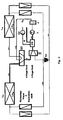
- the centerpiece is the series connection of a refrigerant / water heat exchanger WW with a mass flow W regulated on the water side and a coolant / air heat exchanger LW Zu or LW Ab , for which a bypass is provided.
- the WP water pump makes it easy to regulate the heat extraction from the refrigerant. If there is a need for warm water, but not for heating energy, the WP pump is operated at the nominal speed. This removes the heat from the refrigerant until it cools down and the liquid refrigerant flows into the refrigerant collector KS.
- the three-way valve can even be replaced with a simple solenoid valve.
- the WP pump is switched off. In this case, only the content of the heat exchanger WW heats up without releasing heat to the hot water circuit W. If it is structurally arranged in the supply air L Zu , its heat emission only serves to heat the supply air.
- the WP pump can also be used be operated at a lower speed than the nominal speed. This will only part of the heat is transferred to the water, the rest goes to the supply air.
- a speed-controlled pump with an upstream inverter the flow can be regulated continuously.
- a temperature sensor at the water outlet of the heat exchanger a defined outlet temperature of the water can thus be set within wide operating limits. In this way, a high level of domestic water comfort can be achieved, since water of the desired temperature is very quickly available in a hot water tank. Since the desired final temperature is reached immediately, a charging lance could be dispensed with in a buffer storage concept.
- the relatively high price of the regulated pump, the inverter and the sensor must be taken into account.
- the inverter may have no or at least very little standby power consumption.
- a defined water mass flow for mixed operation can be set with a two-stage pump.
- the difference in speed can be limited. This concept has the advantage of very simple regulation and lower costs, but cannot guarantee the comfort described above.
- a Loading device Due to the lower density of the heated water, it flows through a Loading device - preferably a layer lance with loading openings in several heights - up to a height with the same temperature in the storage tank.
- This Principle is used in thermosiphon solar collectors (standard in the Mediterranean) and previously used in gravity heating.
- the operation of the heat pump WP in hot water operation is shown in Figure 2.
- the water pump WP runs at the highest speed, so that the entire desuperheating, Condensation and subcooling in the WW refrigerant / water heat exchanger takes place.
- the three-way valve releases the bypass to the refrigerant collector.
- the Arrows on the lines indicate the direction of the refrigerant mass flow.
- Figure 2 shows as a legend which material flows are tempered and how.
- the thick lines correspond to a warm material flow
- the normal solid Line corresponds to a warmed material flow
- the zigzag executed Line shape corresponds to a cold material flow.
- On the so introduced Line meaning is also referred to accordingly in the other figures.
- the circulation in the mass flow in FIG. 3 takes place as follows:
- the superheated refrigerant flows through WW, which comes from the heat exchanger L Ab via the 4-way valve and the separator.
- From the heat exchanger DHW the superheated refrigerant passes unchanged through the three-way valve and the 4-way valve to the Zutuftebenübertrager LW to.
- the supply air is heated here, whereby the refrigerant mass flow flowing in the line is liquefied.
- the electricity flows through a non-return valve into the refrigerant collector KS and via an expansion valve back into the exhaust air heat exchanger LW Ab .
- FIG. 5 A cooling operation with simultaneous water heating is shown in FIG. 5: If there is a need for hot water in summer that is not adequately covered by a thermal solar system, the heat of the supply air can be extracted by switching over the four-way valve. This means that comfort can be achieved by cooling the living rooms at the same time.
- FIG 6 is a ventilation arrangement for cooling the supply air when the Excess heat given to the exhaust air.
- This circuit arrangement is suitable especially for defrosting the evaporator.
- the heat pump WP is also suitable for pure cooling of the ventilated rooms.
- the three-way valve switches to the refrigerant / air heat exchanger for the exhaust air L Ab .
- the heat provided is generally of no use. So this case should occur as rarely as possible. However, it offers residents greater thermal comfort on particularly hot days and is more efficient than simple split cooling devices that may be used.
- the circuit can also be used to defrost the evaporator LW Ab in winter operation in one of the first three cases.
- the surface of the evaporator which is covered with frost or ice, is actively heated in the moist exhaust air by the heat pump. For this, the enthalpy of solidification of the frozen water must be supplied. The liquid water then flows out through the drain so that the enthalpy of vaporization previously extracted from the water vapor in the exhaust air is retained as heat gain.
- the heat for defrosting becomes the coefficient of performance of the heat pump Provided. For this, the supply air is briefly cooled. This amount of energy the heat pump can then again with the corresponding coefficient of performance compensate for heat generation.
- This defrost is a direct electrical one just as energetically superior as a bypass hot gas defrost.
- this process takes three to six minutes. In At this time, there must not be uncomfortable supply air temperatures in the ventilated Rooms come. For a period to be examined in more detail, the thermal storage mass of the supply air side of the ventilation unit and the Air distribution network to raise the temperature to at least 17 ° C. This time must not be exceeded during the defrosting process. On the other hand, needs the heat pump after a defrost a certain time until the Performance figures of constant operation are restored. Between these Both goals are an optimization in the concrete design of the heat pump perform.
Landscapes
- Engineering & Computer Science (AREA)
- Mechanical Engineering (AREA)
- General Engineering & Computer Science (AREA)
- Physics & Mathematics (AREA)
- Thermal Sciences (AREA)
- Combustion & Propulsion (AREA)
- Chemical & Material Sciences (AREA)
- Life Sciences & Earth Sciences (AREA)
- Sustainable Development (AREA)
- Heat-Pump Type And Storage Water Heaters (AREA)
- Building Environments (AREA)
- Ventilation (AREA)
- Other Air-Conditioning Systems (AREA)
- Central Air Conditioning (AREA)
Claims (12)
- Utilisation d'un dispositif d'aération pour bâtiment avec extraction de chaleur d'un courant d'air d'échappement (LAb) dirigé hors du bâtiment et/ou d'un courant d'air d'alimentation (LZu) dirigé dans le bâtiment,comportant une pompe à chaleur qui prévoit un échangeur de chaleur à produit refroidisseur/à eau (WW) qui présente du côté de l'eau un flux massique réglable à intervalles réguliers ou en continu, un échangeur de chaleur à produit refroidisseur/à air (LWAb) servant pour le courant d'air d'échappement (LAb) et un échangeur de chaleur à produit refroidisseur/à air (LWZu) servant pour le courant d'air d'alimentation (LZu), les échangeurs de chaleur à produit refroidisseur/à air (LWZu) et (LWAb) étant connectables respectivement en série à l'échangeur de chaleur à produit refroidisseur/à eau (WW), et
l'échangeur de chaleur à produit refroidisseur/à eau (WW) présentant une conduite d'alimentation en produit refroidisseur (KZu) dans laquelle est prévu un compresseur (V) et qui est reliée à l'échangeur de chaleur à produit refroidisseur/à air (LWAb) servant pour le courant d'air d'échappement (LWAb) et qui contient un produit refroidisseur chauffé sous forme gazeuse qui provient de l'échangeur de chaleur à produit refroidisseur/à air (LWAb) faisant office de vaporisateur, qui est son tour connecté à l'échangeur de chaleur à produit refroidisseur/à eau (WW),pour chauffer le flux massique d'eau (W), de la chaleur du courant d'air d'échappement (LAb) étant acheminée au produit refroidisseur à l'intérieur de l'échangeur de chaleur à produit refroidisseur/à air (LWAb) par évaporation du produit refroidisseur et le produit refroidisseur sous forme gazeuse étant ensuite acheminé au compresseur (V) grâce auquel le produit refroidisseur subit par compression une autre chauffe dont la chaleur est envoyée du moins partiellement au flux massique d'eau (W) dans l'échangeur de chaleur à produit refroidisseur/à eau (WW). - Utilisation selon la revendication 1, caractérisée en ce que la régulation du flux massique d'eau est réalisé au moyen d'une pompe à eau (WP) et que la pompe à eau (WP) fonctionne avec une grande capacité de transport, de préférence maximale.
- Utilisation d'un dispositif d'aération pour bâtiment avec extraction de chaleur d'un courant d'air d'échappement (LAb) dirigé hors du bâtiment et/ou d'un courant d'air d'alimentation (LZu) dirigé dans le bâtiment,comportant une pompe à chaleur qui prévoit un échangeur de chaleur à produit refroidisseur/à eau (WW) qui présente du côté de l'eau un flux massique réglable à intervalles réguliers ou en continu au moyen d'une pompe à eau (WP), un échangeur de chaleur à produit refroidisseur/à air (LWAb) servant pour le courant d'air d'échappement (LAb) et un échangeur de chaleur à produit refroidisseur/à air (LWZu) servant pour le courant d'air d'alimentation (LZu), les échangeurs de chaleur à produit refroidisseur/à air (LWZu) et (LWAb) étant connectables respectivement en série à l'échangeur de chaleur à produit refroidisseur/à eau (WW), et l'échangeur de chaleur à produit refroidisseur/à eau (WW) présentant une conduite d'alimentation en produit refroidisseur (KZu) dans laquelle est prévu un compresseur (V) et qui est reliée à l'échangeur de chaleur à produit refroidisseur/à air (LWAb) servant pour le courant d'air d'échappement (LAb) et qui contient un produit refroidisseur chauffé sous forme gazeuse qui provient de l'échangeur de chaleur à produit refroidisseur/à air (LWAb) faisant office de vaporisateur, qui est relié à l'échangeur de chaleur à produit refroidisseur/à air (LWZu) servant pour le courant d'air d'alimentation (LZu) et faisant office de condenseur, qui est son tour connecté à l'échangeur de chaleur à produit refroidisseur/à eau (WW),pour chauffer le courant d'air d'alimentation (LZu), la pompe à eau (WP) étant installée et de la chaleur du courant d'air d'échappement (LAb) étant acheminée au produit refroidisseur à l'intérieur de l'échangeur de chaleur à produit refroidisseur/à air (LWAb) par évaporation du produit refroidisseur et le produit refroidisseur sous forme gazeuse étant ensuite acheminé au compresseur (V) grâce auquel le produit refroidisseur subit par compression une autre chauffe et par lequel le produit refroidisseur chauffé sous forme gazeuse est acheminé à l'échangeur de chaleur à produit refroidisseur/à air (LWZu) faisant office de condensateur, qui chauffe le courant d'air d'alimentation (LZu).
- Utilisation selon la revendication 3 et chauffe simultanée du flux massique d'eau (W) par mise en route de la pompe à eau (WP) grâce à laquelle, en cas d'une faible capacité de transport ou d'un faible régime, une partie de la chaleur du produit refroidisseur sous forme gazeuse chauffé davantage est transférée à l'intérieur de l'échangeur de chaleur à produit refroidisseur/à eau (WW) au flux massique d'eau (W).
- Utilisation d'un dispositif d'aération pour bâtiment avec extraction de chaleur d'un courant d'air d'échappement (LAb) dirigé hors du bâtiment et/ou d'un courant d'air d'alimentation (LZu) dirigé dans le bâtiment,comportant une pompe à chaleur qui prévoit un échangeur de chaleur à produit refroidisseur/à eau (WW) qui présente du côté de l'eau un flux massique réglable à intervalles réguliers ou en continu, un échangeur de chaleur à produit refroidisseur/à air (LWAb) servant pour le courant d'air d'échappement (LAb) et un échangeur de chaleur à produit refroidisseur/à air (LWZu) servant pour le courant d'air d'alimentation (LZu), les échangeurs de chaleur à produit refroidisseur/à air (LWZu) et (LWAb) étant connectables respectivement en série à l'échangeur de chaleur à produit refroidisseur/à eau (WW), etl'échangeur de chaleur à produit refroidisseur/à eau (WW) présentant une conduite d'alimentation en produit refroidisseur (KZu) dans laquelle est prévu un compresseur (V) et qui est reliée à l'échangeur de chaleur à produit refroidisseur/à air (LWZu) servant pour le courant d'air d'alimentation (LZu), la conduite d'alimentation en produit refroidisseur (KZu) contenant du produit refroidisseur chauffé sous forme gazeuse qui provient de l'échangeur de chaleur à produit refroidisseur/à air (LWZu) faisant office de vaporisateur, qui est connecté à l'échangeur de chaleur à produit refroidisseur/à eau (WW),pour refroidir le courant d'air d'alimentation (LZu) par extraction de chaleur
de l'air d'alimentation au moyen du produit refroidisseur, qui est acheminé sous forme liquide à l'échangeur de chaleur à produit refroidisseur/à air (LWZu) faisant office de vaporisateur. - Utilisation selon la revendication 5 et chauffe simultanée du flux massique d'eau (W) par acheminement du produit refroidisseur chauffé, évaporé et sous forme gazeuse à l'échangeur de chaleur à produit refroidisseur/à eau (WW), une pompe à eau (WP) transportant de l'eau (W) à travers l'échangeur de chaleur à produit refroidisseur/à eau (WW).
- Utilisation selon la revendication 5 et chauffe simultanée du courant d'air d'échappement (LAb) pour dégivrage intentionnel de l'échangeur de chaleur à produit refroidisseur/à air (LWAb) par acheminement du produit refroidisseur chauffé, évaporé et sous forme gazeuse à l'échangeur de chaleur à produit refroidisseur/à air (LWAb) faisant office de condensateur.
- Utilisation selon l'une quelconque des revendications 1 à 7, caractérisée en ce que la régulation du flux massique est réalisée au moyen d'une pompe à eau (WP) qui transporte avec un régime régulé ou au moyen de plusieurs niveaux de régime distincts un flux massique d'eau (W) à l'échangeur de chaleur à produit refroidisseur/à eau (WW) et transporte le flux massique depuis l'arrêt total jusqu'à une capacité de transport maximale.
- Utilisation selon l'une quelconque des revendications 1 à 8, caractérisée en ce que la régulation du flux massique est réalisée au moyen d'une pompe à eau (WP) à plusieurs niveaux de régime, dont la régulation se fait en utilisant le comportement de l'eau alternant entre un flux laminaire et un flux à turbulences à l'intérieur de l'échangeur de chaleur (WW).
- Utilisation selon l'une quelconque des revendications 1 ou 3, caractérisée en ce que la régulation du flux massique est réalisée en utilisant partiellement ou exclusivement la poussée verticale de l'eau chauffée dans l'échangeur de chaleur (WW).
- Utilisation selon l'une quelconque des revendications 1 à 10, caractérisée en ce que la conduite d'alimentation en produit refroidisseur (KZu) est connectable par une soupape à quatre distributions à l'échangeur de chaleur à produit refroidisseur/à air (LWZu) ou (LWAb).
- Utilisation selon la revendication 11, caractérisée en ce que l'échangeur de chaleur à produit refroidisseur/à eau (WW) est connectable par une soupape à trois distributions (3V) ou une soupape à quatre distributions (4V) au collecteur de produit refroidisseur et/ou en plus par la soupape à quatre distributions (4V) à l'échangeur de chaleur à produit refroidisseur/à air (LWZu) ou (LWAb).
Applications Claiming Priority (5)
| Application Number | Priority Date | Filing Date | Title |
|---|---|---|---|
| DE19861020A DE19861020C1 (de) | 1998-11-30 | 1998-11-30 | Lüftungsanordnung für Gebäude |
| DE19861020 | 1998-11-30 | ||
| DE19901871 | 1999-01-19 | ||
| DE19901871 | 1999-01-19 | ||
| PCT/EP1999/009047 WO2000032994A1 (fr) | 1998-11-30 | 1999-11-23 | Systeme de ventilation pour batiments |
Publications (2)
| Publication Number | Publication Date |
|---|---|
| EP1163479A1 EP1163479A1 (fr) | 2001-12-19 |
| EP1163479B1 true EP1163479B1 (fr) | 2004-08-18 |
Family
ID=26051170
Family Applications (1)
| Application Number | Title | Priority Date | Filing Date |
|---|---|---|---|
| EP99973114A Expired - Lifetime EP1163479B1 (fr) | 1998-11-30 | 1999-11-23 | Utilisation d'un systeme de ventilation pour batiments |
Country Status (5)
| Country | Link |
|---|---|
| US (1) | US6606874B1 (fr) |
| EP (1) | EP1163479B1 (fr) |
| AT (1) | ATE274174T1 (fr) |
| DE (1) | DE59910312D1 (fr) |
| WO (1) | WO2000032994A1 (fr) |
Families Citing this family (5)
| Publication number | Priority date | Publication date | Assignee | Title |
|---|---|---|---|---|
| GB0705667D0 (en) * | 2007-03-23 | 2007-05-02 | Viridian Concepts Ltd | Air flow in enclosed spaces |
| FR2922632B1 (fr) * | 2007-10-18 | 2010-01-22 | Aldes Aeraulique | Installation de ventilation mecanique controlee de type double flux thermodynamique reversible |
| FR2950678B1 (fr) * | 2009-09-30 | 2011-10-21 | Aldes Aeraulique | Installation de ventilation mecanique controlee de type double flux thermodynamique reversible avec production d'eau chaude sanitaire |
| US9383126B2 (en) * | 2011-12-21 | 2016-07-05 | Nortek Global HVAC, LLC | Refrigerant charge management in a heat pump water heater |
| CN108240697A (zh) * | 2016-12-27 | 2018-07-03 | 天津孚美孚森机电设备工程有限公司 | 一种复合太阳能空调冷凝热回收系统 |
Family Cites Families (9)
| Publication number | Priority date | Publication date | Assignee | Title |
|---|---|---|---|---|
| US2575325A (en) * | 1948-02-14 | 1951-11-20 | American Gas And Electric Comp | Heat pump system |
| AU532576B2 (en) * | 1979-06-01 | 1983-10-06 | Ventline Manufacturing (Pty.) Ltd. | Energy transfer system |
| US4399664A (en) * | 1981-12-07 | 1983-08-23 | The Trane Company | Heat pump water heater circuit |
| JPS6198955U (fr) * | 1984-12-05 | 1986-06-25 | ||
| US4697434A (en) * | 1985-10-17 | 1987-10-06 | Mitsubishi Denki Kabushiki Kaisha | Prime mover driven air-conditioning and hot-water supplying system |
| US4924681A (en) * | 1989-05-18 | 1990-05-15 | Martin B. DeVit | Combined heat pump and domestic water heating circuit |
| US5050394A (en) * | 1990-09-20 | 1991-09-24 | Electric Power Research Institute, Inc. | Controllable variable speed heat pump for combined water heating and space cooling |
| US5348077A (en) * | 1991-03-29 | 1994-09-20 | Hillman Chris F | Integrated air exchanger |
| US6038879A (en) * | 1995-08-08 | 2000-03-21 | Yvon Turcotte | Combined air exchange and air conditioning unit |
-
1999
- 1999-11-23 EP EP99973114A patent/EP1163479B1/fr not_active Expired - Lifetime
- 1999-11-23 DE DE59910312T patent/DE59910312D1/de not_active Expired - Lifetime
- 1999-11-23 AT AT99973114T patent/ATE274174T1/de active
- 1999-11-23 WO PCT/EP1999/009047 patent/WO2000032994A1/fr not_active Ceased
- 1999-11-23 US US09/831,159 patent/US6606874B1/en not_active Expired - Fee Related
Also Published As
| Publication number | Publication date |
|---|---|
| ATE274174T1 (de) | 2004-09-15 |
| WO2000032994A1 (fr) | 2000-06-08 |
| DE59910312D1 (de) | 2004-09-23 |
| EP1163479A1 (fr) | 2001-12-19 |
| US6606874B1 (en) | 2003-08-19 |
Similar Documents
| Publication | Publication Date | Title |
|---|---|---|
| EP1606564B1 (fr) | Procede et dispositif de recuperation d'energie | |
| AT502029B1 (de) | Einrichtung zur belüftung und beheizung von gebäuden | |
| DE19702903A1 (de) | Klimaanlage mit einer Wärmepumpe | |
| DE1604205A1 (de) | Klimaanlage | |
| DE102017006550A1 (de) | HVACC-Anlage zum Heizen, Lüften, Klimatisieren und zur zentralen Kältemittelversorgung für ein Gebäude | |
| DE2918616A1 (de) | Verfahren und vorrichtung zur optimierung der waermewirtschaft in gebaeuden mit hilfe einer waermepumpe | |
| EP0041658B1 (fr) | Dispositif pour chauffer et refraîchir des pièces climatisées dans des résidences, des serres ou similaires | |
| DE102006029597A1 (de) | Klimadecke | |
| DE102011054257B4 (de) | Klimagerät | |
| EP0115014B1 (fr) | Procédé pour l'économie d'énergie à commande de température d'air dans des bâtiments et bâtiment permettant la mise en oeuvre du procédé | |
| EP1163479B1 (fr) | Utilisation d'un systeme de ventilation pour batiments | |
| DE29720577U1 (de) | Wärmepumpen/Klima-Anlage mit Energiereceycling | |
| DE29706131U1 (de) | Wärmepumpen/Klima-Anlage mit Wärmerückgewinnung | |
| DE19861020C1 (de) | Lüftungsanordnung für Gebäude | |
| DE19622609A1 (de) | Verfahren zum Betreiben einer Wärmepumpe | |
| DE102024114023A1 (de) | System zur Temperierung eines Gebäudes | |
| EP0019124B1 (fr) | Pompe de chaleur et procédé pour son fonctionnement | |
| DE69733009T2 (de) | Energiemanagementsystem zum Übersachen und Verteilen von thermischer Energie mit Wärmetauschern | |
| DE2723503A1 (de) | Klimaanlage fuer ein hochisoliertes gebaeude mit einer belueftungseinrichtung | |
| DE69018086T2 (de) | Verfahren und anordnung zur kühlung eines gebäudes. | |
| DE4325945C2 (de) | Klimakühlturm | |
| EP1376020B2 (fr) | Méthode et dispositif pour tempérer l'air frais servant à la ventilation de locaux | |
| DE2649377A1 (de) | Klimaanlage fuer geschlossene raeume | |
| DE3336495A1 (de) | Verfahren zur energieeinsparung bei der regelung der lufttemperatur in gebaeuden und gebaeude hierzu | |
| DE102022131679A1 (de) | Energiesystem |
Legal Events
| Date | Code | Title | Description |
|---|---|---|---|
| PUAI | Public reference made under article 153(3) epc to a published international application that has entered the european phase |
Free format text: ORIGINAL CODE: 0009012 |
|
| 17P | Request for examination filed |
Effective date: 20010525 |
|
| AK | Designated contracting states |
Kind code of ref document: A1 Designated state(s): AT BE CH CY DE DK ES FI FR GB GR IE IT LI LU MC NL PT SE |
|
| 17Q | First examination report despatched |
Effective date: 20030915 |
|
| RAP1 | Party data changed (applicant data changed or rights of an application transferred) |
Owner name: FRAUNHOFER-GESELLSCHAFT ZUR FOERDERUNG DERANGEWAND |
|
| GRAP | Despatch of communication of intention to grant a patent |
Free format text: ORIGINAL CODE: EPIDOSNIGR1 |
|
| RTI1 | Title (correction) |
Free format text: USE OF A VENTILATION ARRANGEMENT FOR BUILDINGS |
|
| GRAS | Grant fee paid |
Free format text: ORIGINAL CODE: EPIDOSNIGR3 |
|
| GRAA | (expected) grant |
Free format text: ORIGINAL CODE: 0009210 |
|
| AK | Designated contracting states |
Kind code of ref document: B1 Designated state(s): AT BE CH CY DE DK ES FI FR GB GR IE IT LI LU MC NL PT SE |
|
| PG25 | Lapsed in a contracting state [announced via postgrant information from national office to epo] |
Ref country code: NL Free format text: LAPSE BECAUSE OF FAILURE TO SUBMIT A TRANSLATION OF THE DESCRIPTION OR TO PAY THE FEE WITHIN THE PRESCRIBED TIME-LIMIT Effective date: 20040818 Ref country code: IT Free format text: LAPSE BECAUSE OF FAILURE TO SUBMIT A TRANSLATION OF THE DESCRIPTION OR TO PAY THE FEE WITHIN THE PRESCRIBED TIME-LIMIT;WARNING: LAPSES OF ITALIAN PATENTS WITH EFFECTIVE DATE BEFORE 2007 MAY HAVE OCCURRED AT ANY TIME BEFORE 2007. THE CORRECT EFFECTIVE DATE MAY BE DIFFERENT FROM THE ONE RECORDED. Effective date: 20040818 Ref country code: IE Free format text: LAPSE BECAUSE OF FAILURE TO SUBMIT A TRANSLATION OF THE DESCRIPTION OR TO PAY THE FEE WITHIN THE PRESCRIBED TIME-LIMIT Effective date: 20040818 Ref country code: GB Free format text: LAPSE BECAUSE OF FAILURE TO SUBMIT A TRANSLATION OF THE DESCRIPTION OR TO PAY THE FEE WITHIN THE PRESCRIBED TIME-LIMIT Effective date: 20040818 Ref country code: FR Free format text: LAPSE BECAUSE OF FAILURE TO SUBMIT A TRANSLATION OF THE DESCRIPTION OR TO PAY THE FEE WITHIN THE PRESCRIBED TIME-LIMIT Effective date: 20040818 Ref country code: FI Free format text: LAPSE BECAUSE OF FAILURE TO SUBMIT A TRANSLATION OF THE DESCRIPTION OR TO PAY THE FEE WITHIN THE PRESCRIBED TIME-LIMIT Effective date: 20040818 Ref country code: CY Free format text: LAPSE BECAUSE OF FAILURE TO SUBMIT A TRANSLATION OF THE DESCRIPTION OR TO PAY THE FEE WITHIN THE PRESCRIBED TIME-LIMIT Effective date: 20040818 |
|
| REG | Reference to a national code |
Ref country code: GB Ref legal event code: FG4D Free format text: NOT ENGLISH |
|
| REG | Reference to a national code |
Ref country code: CH Ref legal event code: EP |
|
| REG | Reference to a national code |
Ref country code: IE Ref legal event code: FG4D Free format text: GERMAN |
|
| REF | Corresponds to: |
Ref document number: 59910312 Country of ref document: DE Date of ref document: 20040923 Kind code of ref document: P |
|
| REG | Reference to a national code |
Ref country code: CH Ref legal event code: NV Representative=s name: IP&T RENTSCH UND PARTNER |
|
| PG25 | Lapsed in a contracting state [announced via postgrant information from national office to epo] |
Ref country code: SE Free format text: LAPSE BECAUSE OF FAILURE TO SUBMIT A TRANSLATION OF THE DESCRIPTION OR TO PAY THE FEE WITHIN THE PRESCRIBED TIME-LIMIT Effective date: 20041118 Ref country code: GR Free format text: LAPSE BECAUSE OF FAILURE TO SUBMIT A TRANSLATION OF THE DESCRIPTION OR TO PAY THE FEE WITHIN THE PRESCRIBED TIME-LIMIT Effective date: 20041118 Ref country code: DK Free format text: LAPSE BECAUSE OF FAILURE TO SUBMIT A TRANSLATION OF THE DESCRIPTION OR TO PAY THE FEE WITHIN THE PRESCRIBED TIME-LIMIT Effective date: 20041118 |
|
| PG25 | Lapsed in a contracting state [announced via postgrant information from national office to epo] |
Ref country code: LU Free format text: LAPSE BECAUSE OF NON-PAYMENT OF DUE FEES Effective date: 20041123 |
|
| PG25 | Lapsed in a contracting state [announced via postgrant information from national office to epo] |
Ref country code: ES Free format text: LAPSE BECAUSE OF FAILURE TO SUBMIT A TRANSLATION OF THE DESCRIPTION OR TO PAY THE FEE WITHIN THE PRESCRIBED TIME-LIMIT Effective date: 20041129 |
|
| PG25 | Lapsed in a contracting state [announced via postgrant information from national office to epo] |
Ref country code: MC Free format text: LAPSE BECAUSE OF NON-PAYMENT OF DUE FEES Effective date: 20041130 Ref country code: BE Free format text: LAPSE BECAUSE OF NON-PAYMENT OF DUE FEES Effective date: 20041130 |
|
| NLV1 | Nl: lapsed or annulled due to failure to fulfill the requirements of art. 29p and 29m of the patents act | ||
| GBV | Gb: ep patent (uk) treated as always having been void in accordance with gb section 77(7)/1977 [no translation filed] |
Effective date: 20040818 |
|
| REG | Reference to a national code |
Ref country code: IE Ref legal event code: FD4D |
|
| BERE | Be: lapsed |
Owner name: FRAUNHOFER-GESELLSCHAFT ZUR FORDERUNG DER ANGEWAND Effective date: 20041130 |
|
| PLBE | No opposition filed within time limit |
Free format text: ORIGINAL CODE: 0009261 |
|
| STAA | Information on the status of an ep patent application or granted ep patent |
Free format text: STATUS: NO OPPOSITION FILED WITHIN TIME LIMIT |
|
| 26N | No opposition filed |
Effective date: 20050519 |
|
| EN | Fr: translation not filed | ||
| REG | Reference to a national code |
Ref country code: CH Ref legal event code: PFA Owner name: FRAUNHOFER-GESELLSCHAFT ZUR FOERDERUNG DER ANGEWA Free format text: FRAUNHOFER-GESELLSCHAFT ZUR FOERDERUNG DER ANGEWANDTEN FORSCHUNG E.V.#HANSASTRASSE 27 C#80686 MUENCHEN (DE) -TRANSFER TO- FRAUNHOFER-GESELLSCHAFT ZUR FOERDERUNG DER ANGEWANDTEN FORSCHUNG E.V.#HANSASTRASSE 27 C#80686 MUENCHEN (DE) |
|
| BERE | Be: lapsed |
Owner name: *FRAUNHOFER-GESELLSCHAFT ZUR FORDERUNG DER ANGEWAN Effective date: 20041130 |
|
| PG25 | Lapsed in a contracting state [announced via postgrant information from national office to epo] |
Ref country code: PT Free format text: LAPSE BECAUSE OF NON-PAYMENT OF DUE FEES Effective date: 20050118 |
|
| REG | Reference to a national code |
Ref country code: CH Ref legal event code: PCAR Free format text: RENTSCH & PARTNER;FRAUMUENSTERSTRASSE 9, POSTFACH 2441;8022 ZUERICH (CH) |
|
| PGFP | Annual fee paid to national office [announced via postgrant information from national office to epo] |
Ref country code: AT Payment date: 20101119 Year of fee payment: 12 |
|
| PGFP | Annual fee paid to national office [announced via postgrant information from national office to epo] |
Ref country code: CH Payment date: 20101124 Year of fee payment: 12 |
|
| REG | Reference to a national code |
Ref country code: CH Ref legal event code: PFA Owner name: FRAUNHOFER-GESELLSCHAFT ZUR FOERDERUNG DER ANGEWA Free format text: FRAUNHOFER-GESELLSCHAFT ZUR FOERDERUNG DER ANGEWANDTEN FORSCHUNG E.V.#HANSASTRASSE 27 C#80686 MUENCHEN (DE) -TRANSFER TO- FRAUNHOFER-GESELLSCHAFT ZUR FOERDERUNG DER ANGEWANDTEN FORSCHUNG E.V.#HANSASTRASSE 27 C#80686 MUENCHEN (DE) |
|
| REG | Reference to a national code |
Ref country code: DE Ref legal event code: R084 Ref document number: 59910312 Country of ref document: DE Effective date: 20111007 |
|
| REG | Reference to a national code |
Ref country code: CH Ref legal event code: PL |
|
| PG25 | Lapsed in a contracting state [announced via postgrant information from national office to epo] |
Ref country code: LI Free format text: LAPSE BECAUSE OF NON-PAYMENT OF DUE FEES Effective date: 20111130 Ref country code: CH Free format text: LAPSE BECAUSE OF NON-PAYMENT OF DUE FEES Effective date: 20111130 |
|
| REG | Reference to a national code |
Ref country code: AT Ref legal event code: MM01 Ref document number: 274174 Country of ref document: AT Kind code of ref document: T Effective date: 20111123 |
|
| PG25 | Lapsed in a contracting state [announced via postgrant information from national office to epo] |
Ref country code: AT Free format text: LAPSE BECAUSE OF NON-PAYMENT OF DUE FEES Effective date: 20111123 |
|
| PGFP | Annual fee paid to national office [announced via postgrant information from national office to epo] |
Ref country code: DE Payment date: 20130122 Year of fee payment: 14 |
|
| REG | Reference to a national code |
Ref country code: DE Ref legal event code: R119 Ref document number: 59910312 Country of ref document: DE Effective date: 20140603 |
|
| PG25 | Lapsed in a contracting state [announced via postgrant information from national office to epo] |
Ref country code: DE Free format text: LAPSE BECAUSE OF NON-PAYMENT OF DUE FEES Effective date: 20140603 |