EP1163508B1 - Vorrichtung zur untersuchung von flächenware aus polymeren werkstoffen mit eingebetteten textilen festigkeitsträgern - Google Patents
Vorrichtung zur untersuchung von flächenware aus polymeren werkstoffen mit eingebetteten textilen festigkeitsträgern Download PDFInfo
- Publication number
- EP1163508B1 EP1163508B1 EP00943825A EP00943825A EP1163508B1 EP 1163508 B1 EP1163508 B1 EP 1163508B1 EP 00943825 A EP00943825 A EP 00943825A EP 00943825 A EP00943825 A EP 00943825A EP 1163508 B1 EP1163508 B1 EP 1163508B1
- Authority
- EP
- European Patent Office
- Prior art keywords
- nmr
- measurement
- flat goods
- probe
- mouse
- Prior art date
- Legal status (The legal status is an assumption and is not a legal conclusion. Google has not performed a legal analysis and makes no representation as to the accuracy of the status listed.)
- Expired - Lifetime
Links
- 239000000463 material Substances 0.000 title claims abstract description 55
- 239000004753 textile Substances 0.000 title claims description 17
- 238000004458 analytical method Methods 0.000 claims abstract description 10
- 238000005259 measurement Methods 0.000 claims description 47
- 239000000523 sample Substances 0.000 abstract description 93
- 230000002787 reinforcement Effects 0.000 abstract description 17
- 238000013421 nuclear magnetic resonance imaging Methods 0.000 abstract 1
- 230000010287 polarization Effects 0.000 description 9
- 239000002861 polymer material Substances 0.000 description 9
- 239000000835 fiber Substances 0.000 description 6
- 238000005160 1H NMR spectroscopy Methods 0.000 description 5
- 229920001971 elastomer Polymers 0.000 description 4
- 239000004744 fabric Substances 0.000 description 4
- 238000005481 NMR spectroscopy Methods 0.000 description 3
- 239000004952 Polyamide Substances 0.000 description 3
- 239000000806 elastomer Substances 0.000 description 3
- 238000011835 investigation Methods 0.000 description 3
- 229920002647 polyamide Polymers 0.000 description 3
- 230000035945 sensitivity Effects 0.000 description 3
- 238000012360 testing method Methods 0.000 description 3
- 230000007547 defect Effects 0.000 description 2
- 230000001066 destructive effect Effects 0.000 description 2
- 238000003384 imaging method Methods 0.000 description 2
- 238000000034 method Methods 0.000 description 2
- 238000011160 research Methods 0.000 description 2
- 230000011664 signaling Effects 0.000 description 2
- 238000004293 19F NMR spectroscopy Methods 0.000 description 1
- 229920000049 Carbon (fiber) Polymers 0.000 description 1
- 229920000742 Cotton Polymers 0.000 description 1
- 239000004372 Polyvinyl alcohol Substances 0.000 description 1
- 239000004760 aramid Substances 0.000 description 1
- 229920006231 aramid fiber Polymers 0.000 description 1
- 230000033228 biological regulation Effects 0.000 description 1
- 239000004917 carbon fiber Substances 0.000 description 1
- 229920002678 cellulose Polymers 0.000 description 1
- 239000001913 cellulose Substances 0.000 description 1
- 238000012512 characterization method Methods 0.000 description 1
- 230000001419 dependent effect Effects 0.000 description 1
- 238000013461 design Methods 0.000 description 1
- 238000001514 detection method Methods 0.000 description 1
- 239000013536 elastomeric material Substances 0.000 description 1
- 238000005516 engineering process Methods 0.000 description 1
- 230000005284 excitation Effects 0.000 description 1
- 239000003365 glass fiber Substances 0.000 description 1
- 125000004435 hydrogen atom Chemical class [H]* 0.000 description 1
- 238000004519 manufacturing process Methods 0.000 description 1
- 238000013507 mapping Methods 0.000 description 1
- 239000012528 membrane Substances 0.000 description 1
- 239000002557 mineral fiber Substances 0.000 description 1
- 229920003052 natural elastomer Polymers 0.000 description 1
- 229920001194 natural rubber Polymers 0.000 description 1
- 229920000728 polyester Polymers 0.000 description 1
- 229920000642 polymer Polymers 0.000 description 1
- 229920002451 polyvinyl alcohol Polymers 0.000 description 1
- 238000007639 printing Methods 0.000 description 1
- 239000005060 rubber Substances 0.000 description 1
- 238000007493 shaping process Methods 0.000 description 1
- 230000003068 static effect Effects 0.000 description 1
- 238000005728 strengthening Methods 0.000 description 1
- 229920003051 synthetic elastomer Polymers 0.000 description 1
- 239000012209 synthetic fiber Substances 0.000 description 1
- 229920002994 synthetic fiber Polymers 0.000 description 1
- 239000005061 synthetic rubber Substances 0.000 description 1
- 229920001169 thermoplastic Polymers 0.000 description 1
- 229920002725 thermoplastic elastomer Polymers 0.000 description 1
- 229920001187 thermosetting polymer Polymers 0.000 description 1
- 239000004416 thermosoftening plastic Substances 0.000 description 1
- 238000004073 vulcanization Methods 0.000 description 1
Images


Classifications
-
- G—PHYSICS
- G01—MEASURING; TESTING
- G01R—MEASURING ELECTRIC VARIABLES; MEASURING MAGNETIC VARIABLES
- G01R33/00—Arrangements or instruments for measuring magnetic variables
- G01R33/20—Arrangements or instruments for measuring magnetic variables involving magnetic resonance
- G01R33/28—Details of apparatus provided for in groups G01R33/44 - G01R33/64
-
- G—PHYSICS
- G01—MEASURING; TESTING
- G01N—INVESTIGATING OR ANALYSING MATERIALS BY DETERMINING THEIR CHEMICAL OR PHYSICAL PROPERTIES
- G01N24/00—Investigating or analyzing materials by the use of nuclear magnetic resonance, electron paramagnetic resonance or other spin effects
- G01N24/08—Investigating or analyzing materials by the use of nuclear magnetic resonance, electron paramagnetic resonance or other spin effects by using nuclear magnetic resonance
- G01N24/085—Analysis of materials for the purpose of controlling industrial production systems
Definitions
- the invention relates to a device for examining flat goods made of polymeric materials with embedded textile reinforcements.
- Sheets made of polymeric materials with textile reinforcements that are used for Reinforcement and shaping are embedded in the polymer material is known.
- Sheeting made from such polymeric materials, the elastomers, thermoplastic elastomers, thermoplastics and thermosets include serve especially for use in roof coverings, as printing blankets, conveyor belts, Membranes as well as cylindrical sheets in air springs, hoses and Compensators.
- the object of the invention is to provide a device with which the Flat goods as completely as possible with regard to the arrangement and course of the Strength members in the polymeric material can be examined non-destructively. In particular, unwanted defects, e.g. unequal distances of the Strength members or missing strength members can be determined. there the quality of the surface goods should not be due to the examination method be affected.
- the device should have a simple structure with good Work contrast.
- NMR MOUSE probes (Nuclear Magnetic Resonance MObile Universal Surface Explorer) are known for material analysis in materials research, see G. Eidmann et al, "The NMR-MOUSE, a Mobile Universal Surface Explorer," Journal of Magnetic Resonance (J.Magn.Res.) A122, 1996, pp. 104/109, and A. Guthausen et al, "Analysis of Polymer Materials by Surface NMR via the MOUSE", J.Magn.Reson. A129, 1997, p.001 / 007, and A. Guthausen et al, "NMR imaging and materials research ", Chemistry of our time, 1998, p.73 / 82.
- NMR-MOUSE probes is determined by magnetic resonance (NMR) in one of the surface of the An NMR signal is generated and measured in the vicinity of the probe Characterization of the properties of the near-surface area of the NMR-MOUSE probe arranged materials is exploited polymeric materials with textile reinforcements exist in the sense of practically feasible measurement of the nuclear magnetic resonance of the Hydrogen nucleus 1H (1H-NMR) from signaling areas, namely the polymeric material, and a material that - like the textile reinforcement - little to no signal. To examine the position of the textile Strength in the polymeric material is therefore already the usual one experimental conditions less demanding mapping of the spin density sufficient. An introduction of relaxation contrast is to evaluate the Test results are not necessarily required, but neither disturbing.
- the core 19F may also be used for area products with NMR MOUSE probes. Lies 19F only in the material of the textile reinforcement, so the textile Strength members can be imaged directly by 19F-NMR.
- the analysis of the flat goods made of polymer material with textiles Strength beams with NMR MOUSE probes are particularly advantageous because 1) the Sensitivity of measurement of the NMR MOUSE probes at shallow depths sensitive volume of the probe (e.g. 0 to 3 mm) is particularly high and 2) soft matter such as polymers is particularly suitable for NMR imaging. If one dispenses with a homogeneous magnetic polarization field B0 and homogeneous high-frequency field B1, the NMR-MOUSE probes can in the ratio to be built small compared to conventional NMR devices.
- the NMR MOUSE probes arranged in the measuring plane mutually overlapping to the Examine surface goods as extensively as possible in one direction in the material can, especially in such a way that their sensitive volume ranges in overlap this direction, claim 3.
- the measurement can be carried out at an elevated temperature at which the rubber molecules move more thermally.
- the surface goods are examined warm.
- the examination can take place during and / or immediately after the production process, the vulcanization.
- the examination temperature is limited by the Curie temperature of the material, the temperature of the fabric must be below the Curie temperature.
- the gain in measurement sensitivity associated with this measurement can be offset by a loss of contrast due to the different NMR relaxation times, but an increase in the measurement sensitivity is of greater importance for the area product to be examined here.
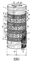
- Figures 1 and 2 show devices for examining flat goods polymeric material with measuring bodies 1 and 2, the NMR MOUSE probes exhibit.
- the devices are used for Examination of a pneumatically resilient component made of natural or synthetic rubber, which to increase its resilience textile Strength members are attached.
- the textile reinforcements in the polymer material consist of aramid fibers or polyamide fibers in the exemplary embodiments. Polyester, mineral fibers (e.g. glass fiber), carbon fibers, fibers are also suitable from acetylated polyvinyl alcohol, reon fibers (semi-synthetic fibers e.g. with Cellulose) or, for example, cotton.
- embedded strength members are fibers made of one material, compared to the polymeric base material in which they are embedded, one has lower 1H or 19F density or the other NMR relaxation times having.
- the measuring body 1 which is cylindrical in shape, is particularly for testing tubular fabric 3 determined, with the measuring body 2 are flat Material webs 4 can be examined as flat goods.
- the polymeric material is traversed by reinforcements 7, the location of which in the area product 3 or 4 is shown only schematically in the drawing.
- the strength members 7 pass through the polymer Material at a distance 8 substantially parallel to each other in a predetermined Direction, in the exemplary embodiment parallel to the longitudinal extension of the hose or sheet-like flat goods 3 or 4.
- the distance 8 between the parallel extending strength members 7 is approximately 0.5 to 1 mm.
- the strength members embedded in the material can also be used in others Be arranged as shown in Figures 1 and 2, for example the material Pull through like a net or cross each other.
- An NMR MOUSE probe shows the polarization of the nuclear magnetic moments in the material to be examined and for generating measurement signals spatially inhomogeneous magnetic fields.
- Figure 3 are at an NMR MOUSE probe 9 between two oppositely magnetized Permanent magnets 10, 11 with permanent magnet poles N and S two Gradient coils 12, 13 and one between the gradient coils High-frequency coil 14.
- the static polarization field B0 which between the Permanent magnet poles is generated by means of the high-frequency coil 14 in time interval pulsating a magnetic measuring field B1 as a magnetic Share of a radio frequency field superimposed with the radio frequency coil as Part of an electrical resonant circuit is formed and received.
- Pulse of the magnetic measuring field B1 is understood to mean that the magnetic field in a predetermined timing by exciting the high frequency coil over a short period is generated intermittently. With the gradient coils 12, 13, also pulsed - the magnetic field additionally a magnetic gradient field BG superimposed.
- the field lines of the gradient field BG are schematic in FIG. 3a entered. Shape and size of the surrounding volume that is in the outer Environment of the NMR MOUSE probe implied nuclear magnetic and by measurement of the echo signals is to be detected and the measurement-sensitive volume range represents for each probe on the one hand due to the specific bandwidth of the magnetic high-frequency excitation and on the other hand by the orthogonal Components of both magnetic fields B0 and B1 defined.
- the course of the magnetic field lines and thus the size of the signaling Volume range can be dimensioned and arranged accordingly Permanent magnets and the coil of the high-frequency electrical resonant circuit to be changed.
- the permanent magnetic polarization field B0 (basic field) is created using the Gradient coils 12, 13 thus additionally have a gradient field BG with a Field gradients tangential to the outer surface of the NMR-MOUSE probe 9 and generated perpendicular to the polarization field B0.
- This additional field BG becomes Generation of the spatial resolution (phase coding of the spatial information) in time Distance pulsed.
- the high-frequency coil 14 is arranged in such a way that the Field lines of the polarization field B0 and the field lines of the by High-frequency coil generated magnetic measuring field B1 in the measurement-sensitive Volume area are perpendicular to each other.
- the orthogonal components of the Both magnetic fields B0 and B1 indicate the measurement signal. For suggestion and The same high-frequency coil is used to detect the measurement signal.
- Adjacent permanent magnet rings 17a, 17b are polarized in opposite directions: this is in addition to the permanent magnet ring 17a, whose magnetic field radially from the outside in the magnetic north / south direction Is directed inside (the magnetic north pole N of the permanent magnet ring 17a is formed by the outer ring surface), at a distance of 18 Permanent magnet ring 17b attached with the opposite magnetic field (The outer ring surface of the permanent magnet ring 17b forms the magnetic South Pole S).
- 16 on the cylindrical measuring body 1 between adjacent permanent magnet rings 17 on the cylinder surface 5 toroidally rotationally symmetrical Permanent magnetic fields B0 generated with which on the cylinder surface of the Measuring body lying material can be penetrated.
- the permanent magnet ring field B0 is the Permanent magnet rings a pulsed magnetic measuring field B1 as a magnetic Share of a high-frequency field can be superimposed, with the gradient coils 19 also pulsed - additionally in the measuring-sensitive volume range Gradient field BG in the tangential direction to the cylinder surface 5 and perpendicular to the permanent magnet ring field B0.
- the Gradient coils can be the permanent magnetic field B0 with the Gradient coils maximally influence the generated gradient fields BG.
- Each sector areas delimited by adjacent gradient coils 19 Permanent magnet rings 17 form together with these gradient coils and between the gradient coils 19 used high-frequency coil 20 an NMR MOUSE probe. Each gradient coil is therefore two to each other assigned to adjacent NMR MOUSE probes.
- FIG. 1 In the embodiment of Figure 1 are in the measuring plane on the cylindrical Measuring body 1 four permanent magnet rings 17 in the axial direction of the cylinder axis 15 arranged sequentially. On the cylinder surface 5 of the measuring body 1 are thus in the measuring range 16 from the radially polarized permanent magnet rings 17 each with opposite magnetic field direction Permanent magnet rings three toroidal, rotationally symmetrical polarization fields B0 generated. Between the permanent magnet rings 17 are three probe rings 22, 23, 24 provided with gradient and high-frequency coils 19 and 20, respectively.
- Figure 1 are the NMR MOUSE probes that work in this way on each probe ring be formed and adjacent to each ring perpendicular to the course of the Strength members are arranged with reference number 9a for the NMR MOUSE probes in the probe ring 22, with reference number 9b for the NMR MOUSE probes in the Probe ring 23 and 9c for the NMR MOUSE probes in the Probe ring 24 specified.
- the shape and size of the measuring body 1 is the Dimensions of the surface product to be examined in the application adapted.
- the NMR MOUSE probes are designed in such a way that surface goods can be examined is, the textile reinforcements are at least about 0.1 mm thick and in one Depth between about 0.2 to 5 mm below the surface in the polymer material are embedded.
- a pneumatically resilient, tubular elastomer covering which has a thickness of 2 mm, with Strengtheners made of 0.2 to 0.5 mm thick polyamide fibers examined that the polymeric material in the middle at a depth of 1 mm in the longitudinal extension of the Pull the hose parallel to each other at a distance of 0.5 to 1 mm.
- the Diameter 25 of the measuring body 1 with the permanent magnet rings 17 is adapted to the hose diameter 80 mm.
- the ring thickness 26 of the Permanent magnet rings parallel to the cylinder axis 15 is 20 mm, the distance 18 between the permanent magnet rings 17 for receiving the gradient and High-frequency coils 19 and 20 are 13 mm long. Overall are on the scope of the measuring body 1 in the exemplary embodiment per ring 22 to 24 12 NMR MOUSE probes distributed.
- the NMR MOUSE probes 9a, 9b, 9c are on the measuring body 1 in the ring planes of the three probe rings 22 to 24 viewed in the direction of the cylinder axis 15 Probe ring 22 to the probe ring 24 in each case at an angle 27 to one another staggered so that the measurement-sensitive volume ranges of the NMR MOUSE probes 9a, 9b, 9c overlap with the target, the tubular one Material in the measuring range 16 if possible over the entire circumference of the hose scan.
- the parallel course of the textile reinforcement in the polymer Material can be completely captured in this way.
- the polymeric material with the textile reinforcements exists in the sense of NMR analysis regarding the concentration of the magnetic magnet to be determined core 1H to be polarized, on the one hand, from such material areas that a strong NMR signal (due to strong 1 H or 19F density or longer transversal relaxation time), namely the areas that only consist of consist of polymeric material, in the exemplary embodiment of elastomeric material, and on the other hand from such material areas, of which little to none Signals go out, namely areas in which in the elastomer textile Strength members run, in the exemplary embodiment polyamide fibers.
- the relevant one measurement-sensitive volume range of an NMR MOUSE probe on a Core area is limited, which is smaller than the space of one NMR MOUSE probe on a probe ring between two gradient coils 19 is taken.
- Figure 4 are in the measurement protocols as characteristic Size for the measurement-sensitive volume ranges 35, 36, 37 of the three NMR-MOUSE probes 9a, 9b, 9c that can be evaluated for the analysis of the flat goods Intervals entered and with the reference numbers of the volume ranges characterized. Outside of these measurement-sensitive volume areas 35, 36, 37 remain with the NMR MOUSE probes due to their technical structure Dead spaces that cannot be used for the measurement.
- these dead spaces of the individual NMR MOUSE probes by mutually displacing the probes from the probe ring Bridged probe ring.
- the NMR MOUSE probes are in a probe ring compared to the NMR MOUSE probes in an adjacent probe ring arranged angularly offset, in the embodiment by the angle 27 such offset that at least the outermost strength member, that of the sensitive Volume range of an NMR MOUSE probe is just recorded, even in the measurement-sensitive volume range of the staggered NMR MOUSE probe falls in the neighboring probe ring.
- the NMR MOUSE probes 9b and 9c in the Probe rings 23 and 24 against each other with respect to the strength member 30b staggered the strength member 30b is both in the edge region of the measurement-sensitive volume area 36 as well as in the edge area of the measurement-sensitive volume range 37 measured.
- the NMR MOUSE probes have the same design Dimension angle 27 to move the probes the same size.
- angle 27 for the overlap of the NMR MOUSE probes can also be smaller be chosen as specified in the embodiment. At a smaller angle are then, to be on the safe side, offset from each other NMR MOUSE probes several strength members in the edge area of the measurement-sensitive volume range measured overlapping.
- the NMR MOUSE probes are designed to be alternately controllable, so that after each measurement with one of the NMR MOUSE probes during the ratio Long signal build-up time at measurement time (signal build-up time approx. 25 ms, measurement time approx. 300 ⁇ s) most of the device hardware that is used to control the gradient and high-frequency coils is needed to accommodate another Data point with another one of the NMR MOUSE probes can. This shortens the total required for the analysis of the material Examination time. Fast switches are required for this, not only for Switch between sending and receiving on one probe, but also for Switching between the probes are suitable.
- each opens at the center of a high-frequency coil 20 Mouths 38a of an air duct 38 which runs centrally in the measuring body 1 and which Overpressure and underpressure can be applied.
- the tubular sheet 3 which on the Cylinder surface 5 of the measuring body 1 rests and the cylinder surface encloses, drawn by negative pressure on the cylindrical measuring plane, the The surface goods are transported at overpressure and from Cylinder surface of loosened surface goods.
- the measuring body 2 shown in detail in FIG. 2 for flat material webs 4 is designed analogously to the measuring body 1. Instead of a cylindrical measuring plane here a flat measuring plane 6 is provided, which is at a distance 39 from one another arranged block-shaped permanent magnets 40 with flat pole faces N or S is formed. High frequency and are between the permanent magnets 40 Gradient coils 41, 42 are used.
- the measuring body 2 has four opposite polarized permanent magnet blocks 40 with three probe zones 43, 44, 45 on, in which the NMR-MOUSE probes are again arranged so offset are that the structure of the planes to be examined as flat goods 4 Material webs in the measuring area of the measuring body 2 is completely detectable.
- the permanent magnets used in the exemplary embodiments for generation the polarization fields B0 can be by electromagnets or replace superconducting or high temperature superconducting magnets.
- the Gradient coils used allow for that on the measuring bodies surface goods lying in the exemplary embodiments are one-dimensional Spatial resolution in the tangential direction on the measurement planes. With others Gradient coils can expand the measurement to two-dimensional spatial resolution become.
Landscapes
- Physics & Mathematics (AREA)
- Condensed Matter Physics & Semiconductors (AREA)
- General Physics & Mathematics (AREA)
- Investigating Or Analyzing Materials By The Use Of Magnetic Means (AREA)
- Investigating Strength Of Materials By Application Of Mechanical Stress (AREA)
- Reinforced Plastic Materials (AREA)
- Treatment Of Fiber Materials (AREA)
- Investigating Materials By The Use Of Optical Means Adapted For Particular Applications (AREA)
Description
- Figur 1
- zylindrischer Meßkörper mit NMR-MOUSE-Sonden
- Figur 2
- Ausschnitt eines flächigen Meßkörpers mit NMR-MOUSE-Sonden
- Figur 3
- Aufbau einer NMR-MOUSE-Sonde mit
- Figur 3a:
- Aufsicht auf eine NMR-MOUSE-Sonde aus Richtung a nach Figur 3b,
- Figur 3b:
- Längsschnitt durch die NMR-MOUSE-Sonde gemäß Schnittlinie b nach Figur 3a
- Figur 4
- Meßbeispiel
Claims (7)
- Vorrichtung zur Untersuchung von Flächenware aus polymerem Werkstoff mit eingebetteten textilen Festigkeitsträgern, dadurch gekennzeichnet, daß zur kernmagnetischen Analyse der Flächenware auf einem Meßkörper (1,2) eine von NMR-MOUSE-Sonden (9) gebildete Meßebene zur Auflage der Flächenware vorgesehen ist.
- Vorrichtung nach Anspruch 1, dadurch gekennzeichnet, daß die NMR-MOUSE-Sonden (9a, 9b, 9c) in der Meßebene sich gegenseitig überlappend angeordnet sind.
- Vorrichtung nach Anspruch 2, dadurch gekennzeichnet, daß die NMR-MOUSE-Sonden (9a, 9b, 9c) sich hinsichtlich ihrer meßempfindlichen Volumenbereiche (35, 36, 37) überlappend angeordnet sind.
- Vorrichtung nach einem der vorhergehenden Ansprüche, dadurch gekennzeichnet, dass zur Untersuchung von Flächenware mit parallel verlaufenden Festigkeitsträgern die NMR-MOUSE-Sonden (9a, 9b, 9c) in der Meßebene benachbart angeordnet und nebeneinander senkrecht zum Verlauf der Festigkeitsträger ausgerichtet sind.
- Vorrichtung nach einem der vorhergehenden Ansprüche, dadurch gekennzeichnet, daß zur Analyse schlauchförmiger Flächenware ein zylindrischer Meßkörper (1) mit zylindrischer Meßebene und ringförmig angeordneten NMR-MOUSE-Sonden (9) vorgesehen ist.
- Vorrichtung nach einem der vorhergehenden Ansprüche, dadurch gekennzeichnet, dass die NMR-MOUSE-Sonden derart ausgebildet sind, dass sie zur Untersuchung warmer Flächenware geeignet sind, wobei die Höhe der Temperatur der Flächenware von der Curie-Temperatur des Sondenmaterials begrenzt ist.
- Vorrichtung nach einem der vorhergehenden Ansprüche, dadurch gekennzeichnet, daß die NMR-MOUSE-Sonden wechselweise ansteuerbar ausgebildet sind.
Applications Claiming Priority (3)
| Application Number | Priority Date | Filing Date | Title |
|---|---|---|---|
| DE19928039 | 1999-06-20 | ||
| DE19928039A DE19928039A1 (de) | 1999-06-20 | 1999-06-20 | Vorrichtung zur Untersuchung von Flächenware aus polymeren Werkstoffen mit eingebetteten textilen Festigkeitsträgern |
| PCT/EP2000/005580 WO2000079253A1 (de) | 1999-06-20 | 2000-06-16 | Vorrichtung zur untersuchung von flächenware aus polymeren werkstoffen mit eingebetteten textilen fertigkeitsträgen |
Publications (2)
| Publication Number | Publication Date |
|---|---|
| EP1163508A1 EP1163508A1 (de) | 2001-12-19 |
| EP1163508B1 true EP1163508B1 (de) | 2002-12-11 |
Family
ID=7911789
Family Applications (1)
| Application Number | Title | Priority Date | Filing Date |
|---|---|---|---|
| EP00943825A Expired - Lifetime EP1163508B1 (de) | 1999-06-20 | 2000-06-16 | Vorrichtung zur untersuchung von flächenware aus polymeren werkstoffen mit eingebetteten textilen festigkeitsträgern |
Country Status (8)
| Country | Link |
|---|---|
| US (2) | US20020084783A1 (de) |
| EP (1) | EP1163508B1 (de) |
| JP (1) | JP2003502662A (de) |
| AT (1) | ATE229647T1 (de) |
| DE (2) | DE19928039A1 (de) |
| HU (1) | HUP0105192A2 (de) |
| PL (1) | PL364764A1 (de) |
| WO (1) | WO2000079253A1 (de) |
Families Citing this family (14)
| Publication number | Priority date | Publication date | Assignee | Title |
|---|---|---|---|---|
| DE19928039A1 (de) * | 1999-06-20 | 2001-01-25 | Intech Thueringen Gmbh | Vorrichtung zur Untersuchung von Flächenware aus polymeren Werkstoffen mit eingebetteten textilen Festigkeitsträgern |
| DE10149636B4 (de) * | 2001-10-09 | 2008-01-10 | Brandtner, Siegfried, Dr. | Verfahren und Vorrichtung zur Detektion einer Flüssig/Flüssiggrenze |
| DE10216587B4 (de) * | 2002-04-14 | 2004-08-05 | Michael Dr. Bruder | Unilaterale NMR-Sonde zur Materialanalyse und deren Verwendung als Sensor |
| DE10216586B4 (de) * | 2002-04-14 | 2004-07-01 | Michael Dr. Bruder | Vorrichtung zur Untersuchung von Flächenware aus polymeren Werkstoffen |
| DE10216588A1 (de) * | 2002-04-14 | 2003-10-30 | Michael Bruder | Verfahren zur Auswertung von Meßergebnissen zur Qualitätskontrolle |
| GB0426957D0 (en) * | 2004-12-08 | 2005-01-12 | Univ Surrey | Apparatus and method for nuclear magnetic resonance |
| US7309986B2 (en) * | 2005-03-21 | 2007-12-18 | The Trustees Of The University Of Pennsylvania | Methods and apparatus for magnetic resonance imaging in inhomogeneous fields |
| DE102005024479B3 (de) * | 2005-05-24 | 2006-11-30 | Bruker Biospin Gmbh | Probenkopf für Kernresonanz-Messungen |
| ATE554402T1 (de) * | 2005-12-22 | 2012-05-15 | Pirelli | Verfahren und vorrichtung zum automatischen analysieren der eigenschaften eines in einem reifen enthaltenen elastomermaterials |
| GB0618514D0 (en) * | 2006-09-20 | 2006-11-01 | Univ Nottingham Trent | Method of detecting interactions on a microarray using nuclear magnetic resonance |
| EP2376902B1 (de) | 2008-12-22 | 2014-06-25 | Pirelli Tyre S.P.A. | On-line-schichtmessung mit nmr |
| FR2949602A1 (fr) | 2009-08-28 | 2011-03-04 | Commissariat Energie Atomique | Dispositif d'aimant permanent cylindrique produisant un champ magnetique controle a une distance de sa surface |
| US9429673B2 (en) * | 2012-09-21 | 2016-08-30 | Vista Clara Inc. | Surface-based NMR measurement |
| CN104452253B (zh) * | 2014-12-31 | 2016-08-24 | 泉州市中研智能机电研究院有限公司 | 摩擦辊验布机 |
Family Cites Families (10)
| Publication number | Priority date | Publication date | Assignee | Title |
|---|---|---|---|---|
| GB1580787A (en) * | 1976-04-14 | 1980-12-03 | Mansfield P | Nuclear magnetic resonance apparatus and methods |
| US4065714A (en) * | 1976-06-21 | 1977-12-27 | Varian Associates, Inc. | Pulsed RF excited spectrometer having improved pulse width control |
| GB1601816A (en) * | 1977-05-27 | 1981-11-04 | Nat Res Dev | Investigation of samples by nmr techniques |
| IE47808B1 (en) * | 1979-02-01 | 1984-06-27 | Trinity College Dublin | Nmr test method for measuring the homogeneity of dispersions of carbon black in rubber compositions |
| FR2621694B1 (fr) * | 1987-10-12 | 1993-11-12 | Institut Francais Petrole | Procede et dispositif pour la caracterisation par son taux de gel d'un echantillon de matiere plastique reticule |
| GB9002863D0 (en) * | 1990-02-08 | 1990-04-04 | Oxford Instr Ltd | Magnetic field generating assembly |
| DE19928039A1 (de) * | 1999-06-20 | 2001-01-25 | Intech Thueringen Gmbh | Vorrichtung zur Untersuchung von Flächenware aus polymeren Werkstoffen mit eingebetteten textilen Festigkeitsträgern |
| FR2795524B1 (fr) * | 1999-06-23 | 2001-08-03 | Commissariat Energie Atomique | Dispositif de mesure rmn portable |
| DE19939626C2 (de) * | 1999-08-20 | 2002-09-26 | Intech Thueringen Gmbh | Verfahren zur Erzeugung von Meßsignalen in Magnetfeldern mit einem NMR-Mouse-Gerät |
| US6489767B1 (en) * | 2000-09-06 | 2002-12-03 | Quantum Magnetics, Inc. | Apparatus for and method of single-sided magnetic resonance imaging with palm-size probe |
-
1999
- 1999-06-20 DE DE19928039A patent/DE19928039A1/de not_active Withdrawn
-
2000
- 2000-06-16 WO PCT/EP2000/005580 patent/WO2000079253A1/de not_active Ceased
- 2000-06-16 EP EP00943825A patent/EP1163508B1/de not_active Expired - Lifetime
- 2000-06-16 DE DE50000922T patent/DE50000922D1/de not_active Expired - Fee Related
- 2000-06-16 JP JP2001505174A patent/JP2003502662A/ja not_active Withdrawn
- 2000-06-16 AT AT00943825T patent/ATE229647T1/de not_active IP Right Cessation
- 2000-06-16 HU HU0105192A patent/HUP0105192A2/hu unknown
- 2000-06-16 PL PL00364764A patent/PL364764A1/xx unknown
-
2001
- 2001-12-18 US US10/026,067 patent/US20020084783A1/en not_active Abandoned
-
2002
- 2002-02-19 US US10/078,069 patent/US20020089330A1/en not_active Abandoned
Also Published As
| Publication number | Publication date |
|---|---|
| US20020084783A1 (en) | 2002-07-04 |
| US20020089330A1 (en) | 2002-07-11 |
| ATE229647T1 (de) | 2002-12-15 |
| EP1163508A1 (de) | 2001-12-19 |
| DE19928039A1 (de) | 2001-01-25 |
| HUP0105192A2 (hu) | 2002-04-29 |
| DE50000922D1 (de) | 2003-01-23 |
| JP2003502662A (ja) | 2003-01-21 |
| PL364764A1 (en) | 2004-12-13 |
| WO2000079253A1 (de) | 2000-12-28 |
Similar Documents
| Publication | Publication Date | Title |
|---|---|---|
| EP1163508B1 (de) | Vorrichtung zur untersuchung von flächenware aus polymeren werkstoffen mit eingebetteten textilen festigkeitsträgern | |
| DE69224192T2 (de) | Apparat und Verfahren zur bildlichen Darstellung der Struktur von diamagnetischen und paramagnetischen Objekten | |
| EP3014259B1 (de) | Sensoranordnung und verfahren zur bestimmung der mechanischen oberflächenspannungen und/oder des gefügezustandes | |
| DE1473696A1 (de) | Verfahren und Vorrichtung zur statischen und dynamischen Materialpruefung mittels magnetischer Rueckkopplung | |
| DE102011104293A1 (de) | Orthogonale Wirbelstromsonde für Prüfungen in mehreren Richtungen | |
| DE202011051413U1 (de) | Magnetresonanztomograf mit Magnetenanordnung zum praktischen Scannen von Versuchstieren | |
| EP2269049A1 (de) | Verfahren und vorrichtung zum detektieren von oberflächennahen defekten mittels streuflussmessung | |
| DE3819541C2 (de) | ||
| WO2003087861A1 (de) | Nmr-sonde zur materialanalyse | |
| DE60129782T2 (de) | Vorrichtung zur magnetischen resonanzbildgebung mit paralleler mehrkanaldetektion | |
| DE102011122481B4 (de) | Verfahren und Anordnung zur Überwachung und Lokalisierung von Materialschäden und Diskontinuitäten in Leichtbau-Verbundstrukturen | |
| WO2022073635A1 (de) | Vorrichtung zur echtheitsprüfung eines datenträgers mit nullfeld-nmr-merkmal | |
| DE19939626C2 (de) | Verfahren zur Erzeugung von Meßsignalen in Magnetfeldern mit einem NMR-Mouse-Gerät | |
| EP0372112A1 (de) | Verfahren und Einrichtung zur Messung mechanischer Eigenspannungen eines ferromagnetischen Körpers | |
| EP0677742B1 (de) | Vorrichtung und Verfahren zur Erfassung der Prüfkopfabhebung bei der zerstörungsfreien Untersuchung von metallischen Werkstoffen mit elektromagnetischen Ultraschallwandlern | |
| EP1371978A1 (de) | Mikrowellenvorrichtung zur Qualitätsprüfung strangförmiger Materialien | |
| DE10216586B4 (de) | Vorrichtung zur Untersuchung von Flächenware aus polymeren Werkstoffen | |
| DE102014209602A1 (de) | Prüfverfahren und Prüfvorrichtung zur zerstörungsfreien Werkstoffprüfung mittels Sonden-Array | |
| DE102022206680A1 (de) | Verfahren und Vorrichtung zur Streuflussprüfung | |
| EP1509780A1 (de) | Bildgebendes nmr-verfahren sowie nmr-vorrichtung | |
| DE1766529A1 (de) | Anordnung zur Ermittlung,Anzeige und/oder Messung von Magnetfeldern | |
| DE102019119278A1 (de) | Messvorrichtung und Verfahren zur Messung von Kräften und/oder Drehmomenten in einem Untersuchungsobjekt aus ferromagnetischem Material | |
| DE102024209822A1 (de) | Untersuchungseinheit, Vorrichtung und Verfahren zur zerstörungsfreien Untersuchung eines elektrisch leitfähigen und/oder ferromagnetischen Werkstücks | |
| DE10216588A1 (de) | Verfahren zur Auswertung von Meßergebnissen zur Qualitätskontrolle | |
| DE102005034839B4 (de) | Sende- und Empfangsspulenanordnung |
Legal Events
| Date | Code | Title | Description |
|---|---|---|---|
| PUAI | Public reference made under article 153(3) epc to a published international application that has entered the european phase |
Free format text: ORIGINAL CODE: 0009012 |
|
| 17P | Request for examination filed |
Effective date: 20010816 |
|
| AK | Designated contracting states |
Kind code of ref document: A1 Designated state(s): AT BE CH CY DE DK ES FI FR GB GR IE IT LI LU MC NL PT SE |
|
| 17Q | First examination report despatched |
Effective date: 20011221 |
|
| GRAG | Despatch of communication of intention to grant |
Free format text: ORIGINAL CODE: EPIDOS AGRA |
|
| GRAG | Despatch of communication of intention to grant |
Free format text: ORIGINAL CODE: EPIDOS AGRA |
|
| GRAH | Despatch of communication of intention to grant a patent |
Free format text: ORIGINAL CODE: EPIDOS IGRA |
|
| RIN1 | Information on inventor provided before grant (corrected) |
Inventor name: PRADO, PABLO Inventor name: GUERLIN, THOMAS Inventor name: BRUDER, MICHAEL Inventor name: BLUEMICH, BERNHARD |
|
| RAP1 | Party data changed (applicant data changed or rights of an application transferred) |
Owner name: BLUEMICH, BERNHARD Owner name: INTECH THUERINGEN GMBH |
|
| GRAH | Despatch of communication of intention to grant a patent |
Free format text: ORIGINAL CODE: EPIDOS IGRA |
|
| GRAA | (expected) grant |
Free format text: ORIGINAL CODE: 0009210 |
|
| AK | Designated contracting states |
Kind code of ref document: B1 Designated state(s): AT BE CH CY DE DK ES FI FR GB GR IE IT LI LU MC NL PT SE |
|
| PG25 | Lapsed in a contracting state [announced via postgrant information from national office to epo] |
Ref country code: NL Free format text: LAPSE BECAUSE OF FAILURE TO SUBMIT A TRANSLATION OF THE DESCRIPTION OR TO PAY THE FEE WITHIN THE PRESCRIBED TIME-LIMIT Effective date: 20021211 Ref country code: IE Free format text: LAPSE BECAUSE OF FAILURE TO SUBMIT A TRANSLATION OF THE DESCRIPTION OR TO PAY THE FEE WITHIN THE PRESCRIBED TIME-LIMIT Effective date: 20021211 Ref country code: GR Free format text: LAPSE BECAUSE OF FAILURE TO SUBMIT A TRANSLATION OF THE DESCRIPTION OR TO PAY THE FEE WITHIN THE PRESCRIBED TIME-LIMIT Effective date: 20021211 Ref country code: FI Free format text: LAPSE BECAUSE OF FAILURE TO SUBMIT A TRANSLATION OF THE DESCRIPTION OR TO PAY THE FEE WITHIN THE PRESCRIBED TIME-LIMIT Effective date: 20021211 |
|
| REF | Corresponds to: |
Ref document number: 229647 Country of ref document: AT Date of ref document: 20021215 Kind code of ref document: T |
|
| REG | Reference to a national code |
Ref country code: GB Ref legal event code: FG4D Free format text: NOT ENGLISH |
|
| REG | Reference to a national code |
Ref country code: CH Ref legal event code: EP |
|
| RAP2 | Party data changed (patent owner data changed or rights of a patent transferred) |
Owner name: BLUEMICH, BERNHARD, PROF. DR. Owner name: BRUDER, MICHAEL, DR. |
|
| REG | Reference to a national code |
Ref country code: IE Ref legal event code: FG4D Free format text: GERMAN |
|
| RIN2 | Information on inventor provided after grant (corrected) |
Free format text: BLUEMICH, BERNHARD, PROF. DR. * BRUDER, MICHAEL, DR. * GUERLIN, THOMAS * PRADO, PABLO |
|
| REF | Corresponds to: |
Ref document number: 50000922 Country of ref document: DE Date of ref document: 20030123 |
|
| PG25 | Lapsed in a contracting state [announced via postgrant information from national office to epo] |
Ref country code: SE Free format text: LAPSE BECAUSE OF FAILURE TO SUBMIT A TRANSLATION OF THE DESCRIPTION OR TO PAY THE FEE WITHIN THE PRESCRIBED TIME-LIMIT Effective date: 20030311 Ref country code: PT Free format text: LAPSE BECAUSE OF FAILURE TO SUBMIT A TRANSLATION OF THE DESCRIPTION OR TO PAY THE FEE WITHIN THE PRESCRIBED TIME-LIMIT Effective date: 20030311 Ref country code: DK Free format text: LAPSE BECAUSE OF FAILURE TO SUBMIT A TRANSLATION OF THE DESCRIPTION OR TO PAY THE FEE WITHIN THE PRESCRIBED TIME-LIMIT Effective date: 20030311 |
|
| NLT2 | Nl: modifications (of names), taken from the european patent patent bulletin |
Owner name: BRUDER, MICHAEL, DR. EN BLUEMICH, BERNHARD, PROF. |
|
| NLV1 | Nl: lapsed or annulled due to failure to fulfill the requirements of art. 29p and 29m of the patents act | ||
| PG25 | Lapsed in a contracting state [announced via postgrant information from national office to epo] |
Ref country code: LU Free format text: LAPSE BECAUSE OF NON-PAYMENT OF DUE FEES Effective date: 20030616 Ref country code: CY Free format text: LAPSE BECAUSE OF FAILURE TO SUBMIT A TRANSLATION OF THE DESCRIPTION OR TO PAY THE FEE WITHIN THE PRESCRIBED TIME-LIMIT Effective date: 20030616 Ref country code: AT Free format text: LAPSE BECAUSE OF NON-PAYMENT OF DUE FEES Effective date: 20030616 |
|
| GBT | Gb: translation of ep patent filed (gb section 77(6)(a)/1977) | ||
| PG25 | Lapsed in a contracting state [announced via postgrant information from national office to epo] |
Ref country code: ES Free format text: LAPSE BECAUSE OF FAILURE TO SUBMIT A TRANSLATION OF THE DESCRIPTION OR TO PAY THE FEE WITHIN THE PRESCRIBED TIME-LIMIT Effective date: 20030627 |
|
| PG25 | Lapsed in a contracting state [announced via postgrant information from national office to epo] |
Ref country code: MC Free format text: LAPSE BECAUSE OF NON-PAYMENT OF DUE FEES Effective date: 20030630 |
|
| REG | Reference to a national code |
Ref country code: IE Ref legal event code: FD4D Ref document number: 1163508E Country of ref document: IE |
|
| ET | Fr: translation filed | ||
| PLBE | No opposition filed within time limit |
Free format text: ORIGINAL CODE: 0009261 |
|
| STAA | Information on the status of an ep patent application or granted ep patent |
Free format text: STATUS: NO OPPOSITION FILED WITHIN TIME LIMIT |
|
| 26N | No opposition filed |
Effective date: 20030912 |
|
| BERE | Be: lapsed |
Owner name: *BLUMICH BERNHARD Effective date: 20030630 Owner name: *INTECH THURINGEN G.M.B.H. Effective date: 20030630 |
|
| PG25 | Lapsed in a contracting state [announced via postgrant information from national office to epo] |
Ref country code: LI Free format text: LAPSE BECAUSE OF NON-PAYMENT OF DUE FEES Effective date: 20040630 Ref country code: CH Free format text: LAPSE BECAUSE OF NON-PAYMENT OF DUE FEES Effective date: 20040630 |
|
| REG | Reference to a national code |
Ref country code: CH Ref legal event code: PL |
|
| PGFP | Annual fee paid to national office [announced via postgrant information from national office to epo] |
Ref country code: FR Payment date: 20060530 Year of fee payment: 7 |
|
| PGFP | Annual fee paid to national office [announced via postgrant information from national office to epo] |
Ref country code: GB Payment date: 20060620 Year of fee payment: 7 |
|
| PGFP | Annual fee paid to national office [announced via postgrant information from national office to epo] |
Ref country code: IT Payment date: 20060630 Year of fee payment: 7 |
|
| PGFP | Annual fee paid to national office [announced via postgrant information from national office to epo] |
Ref country code: DE Payment date: 20060825 Year of fee payment: 7 |
|
| GBPC | Gb: european patent ceased through non-payment of renewal fee |
Effective date: 20070616 |
|
| REG | Reference to a national code |
Ref country code: FR Ref legal event code: ST Effective date: 20080229 |
|
| PG25 | Lapsed in a contracting state [announced via postgrant information from national office to epo] |
Ref country code: DE Free format text: LAPSE BECAUSE OF NON-PAYMENT OF DUE FEES Effective date: 20080101 |
|
| PG25 | Lapsed in a contracting state [announced via postgrant information from national office to epo] |
Ref country code: GB Free format text: LAPSE BECAUSE OF NON-PAYMENT OF DUE FEES Effective date: 20070616 |
|
| PG25 | Lapsed in a contracting state [announced via postgrant information from national office to epo] |
Ref country code: BE Free format text: LAPSE BECAUSE OF NON-PAYMENT OF DUE FEES Effective date: 20030630 |
|
| PG25 | Lapsed in a contracting state [announced via postgrant information from national office to epo] |
Ref country code: FR Free format text: LAPSE BECAUSE OF NON-PAYMENT OF DUE FEES Effective date: 20070702 |
|
| PG25 | Lapsed in a contracting state [announced via postgrant information from national office to epo] |
Ref country code: IT Free format text: LAPSE BECAUSE OF NON-PAYMENT OF DUE FEES Effective date: 20070616 |