EP1163943B1 - Membranfilterplatte für eine Filterpresse sowie Trägerplatte und Membran für eine solche Membranfilterplatte - Google Patents
Membranfilterplatte für eine Filterpresse sowie Trägerplatte und Membran für eine solche Membranfilterplatte Download PDFInfo
- Publication number
- EP1163943B1 EP1163943B1 EP01111354A EP01111354A EP1163943B1 EP 1163943 B1 EP1163943 B1 EP 1163943B1 EP 01111354 A EP01111354 A EP 01111354A EP 01111354 A EP01111354 A EP 01111354A EP 1163943 B1 EP1163943 B1 EP 1163943B1
- Authority
- EP
- European Patent Office
- Prior art keywords
- fastening
- membrane
- ridge
- fastening groove
- groove
- Prior art date
- Legal status (The legal status is an assumption and is not a legal conclusion. Google has not performed a legal analysis and makes no representation as to the accuracy of the status listed.)
- Expired - Lifetime
Links
- 239000012528 membrane Substances 0.000 title claims description 135
- 238000007789 sealing Methods 0.000 claims description 16
- 239000004743 Polypropylene Substances 0.000 claims description 15
- 229920001155 polypropylene Polymers 0.000 claims description 15
- -1 polypropylene Polymers 0.000 claims description 9
- 230000000295 complement effect Effects 0.000 claims description 8
- 229920001971 elastomer Polymers 0.000 claims description 7
- 239000004033 plastic Substances 0.000 claims description 3
- 229920002725 thermoplastic elastomer Polymers 0.000 claims description 3
- 210000004379 membrane Anatomy 0.000 description 77
- 239000007787 solid Substances 0.000 description 7
- 239000000463 material Substances 0.000 description 5
- 239000004744 fabric Substances 0.000 description 4
- 238000004519 manufacturing process Methods 0.000 description 3
- 238000000034 method Methods 0.000 description 3
- 239000000725 suspension Substances 0.000 description 3
- 239000000706 filtrate Substances 0.000 description 2
- 230000000717 retained effect Effects 0.000 description 2
- 235000021463 dry cake Nutrition 0.000 description 1
- 230000000694 effects Effects 0.000 description 1
- 239000012065 filter cake Substances 0.000 description 1
- 238000001914 filtration Methods 0.000 description 1
- 238000003780 insertion Methods 0.000 description 1
- 230000037431 insertion Effects 0.000 description 1
- 238000002955 isolation Methods 0.000 description 1
Images





Classifications
-
- B—PERFORMING OPERATIONS; TRANSPORTING
- B01—PHYSICAL OR CHEMICAL PROCESSES OR APPARATUS IN GENERAL
- B01D—SEPARATION
- B01D25/00—Filters formed by clamping together several filtering elements or parts of such elements
- B01D25/12—Filter presses, i.e. of the plate or plate and frame type
- B01D25/21—Plate and frame presses
- B01D25/215—Construction of the filter plates, frames
-
- B—PERFORMING OPERATIONS; TRANSPORTING
- B01—PHYSICAL OR CHEMICAL PROCESSES OR APPARATUS IN GENERAL
- B01D—SEPARATION
- B01D25/00—Filters formed by clamping together several filtering elements or parts of such elements
- B01D25/28—Leaching or washing filter cakes in the filter handling the filter cake for purposes other than regenerating
- B01D25/282—Leaching or washing filter cakes in the filter handling the filter cake for purposes other than regenerating for drying
- B01D25/285—Leaching or washing filter cakes in the filter handling the filter cake for purposes other than regenerating for drying by compression using inflatable membranes
Definitions
- the invention relates to a membrane filter plate for a filter press according to the preamble of claim 1. Furthermore, the invention relates to a carrier plate and a membrane for a Use in such a membrane filter plate.
- Membrane filter plates for use in filter presses are known in principle. In the Usually several membrane filter plates are clamped together in a filter press, so that a filter chamber is created between the individual membrane filter plates. About a tributary If a suspension is pressed into the filter chamber, the suspension is passed through on the Pressed membrane filter cloth, wherein the solids through the filter cloth in the Filter chamber are retained. The freed from solid elements filtrate is over Outflows led out of the system.
- the membranes can be acted upon with a pressure medium, so that they are separated from a Edge region of the filter chamber in the filter chamber and extend towards each other, so that pressed together during the filtering process solid state elements and be compressed, so that a "filter cake" is formed.
- membrane filter plates are inserted with interchangeable membranes Service.
- the membrane with conventional Fasteners such as e.g. Screws
- the membrane with conventional Fasteners over the entire edge area of the membrane in usually attached uniformly and small distances, often in addition to a Strip element or the like is arranged in the edge region of the membrane to a to produce uniform fastening pressure.
- DE 44 19 865 C1 discloses a membrane filter plate for a filter press, wherein a Membrane is provided for releasably attaching to the filter plate.
- the filter plate points while a circumferentially arranged in the edge region receiving groove, and the membrane has in its edge region on a skirt, which are inserted into the receiving groove can.
- the edge strip has a lower ready than the receiving groove, so that when inserting the edge strip in the receiving groove a receiving gap for a terminal block is formed.
- a disadvantage of this device is that without further special embodiments of the sidebar, the groove and / or the terminal block is still not sure that the edge strip not pressed out of the receiving groove when the area between the membrane and filter plate is acted upon by a pressure medium, so that the membrane is pressed into the filter chamber becomes.
- this may not be a problem be, since the skirting is secured with a backing plate in the filter press, however It may happen, especially in case of incorrect operation, that the membrane at a time is pressurized, in which the counter-plate is lifted from the filter plate. In this case, the edge strip would be pushed out of the receiving groove.
- a fixing and loosening of the membrane still relatively expensive.
- a filter element for a chamber, membrane or filter is also The like and a method for its production, wherein the filter element a Filter medium blank with a mounting frame and a support body with a mounting groove comprises, which is adapted in course and cross section of the mounting frame.
- the publication also discloses various cross-sectional shapes for such a mounting frame held by means of elasticity behind a narrower Nuthals in another groove bottom is, the elasticity of the frame by the material of the frame itself or else by a longitudinal slot, the spring arms generated, is caused.
- a filter element for a filter press which is a filter plate with a substantially rectangular cross-section groove, in turn in the a membrane of a substantially rectangular edge strip can be used, wherein the edge strip inserted perpendicular to a plane of the plate in the groove and in opposite Direction is taken again.
- the membrane with a fastening strip and the support plate with a Fastening provided, wherein the outer contour of the mounting strip of the membrane in essentially corresponds to the inner contour of the mounting groove of the support plate.
- the contours the fastening strip and the fastening groove are designed so that in the mounting groove used fastening strip is solvable only by means of a rotary motion, in the an outer edge line of the fastening strip describes a curved path, that of its Operating position in the mounting groove extends at least partially upwards and inwards, and the unused mounting bar only by an opposite rotational movement can be used in its operating position in the mounting groove.
- rotational movement is to be understood in its most general definition and also encompasses movements around changing fulcrum and with changing radii, as long as the movement at least partially deviates from a linear movement.
- operating position of the fastening strip in the fastening groove is meant the position in which the fastening strip are completely inserted in the fastening groove, so that the contours essentially abut each other.
- the filter plate has a plate plane on, wherein the filter plate is formed generally symmetrically to the plate plane, when on both sides a membrane is provided, wherein between the carrier plates respectively a filter chamber and between the diaphragm and the carrier plate, a pressure chamber is generated.
- a fastening groove is provided, which leads to a surface of the filter plate is open for use of the fastening strip and at least partially perpendicular extends to the plate plane in the filter plate.
- above is meant the direction that perpendicular to the plane of the plate from a bottom of the mounting groove to the opening in the surface of the carrier plate extends.
- below the opposite direction is defined.
- the directions “outside” and “inside” refer to directions that are normal to extend the just defined directions “up” and “down", with “inside” a Direction is defined parallel to the plate plane of the filter or support plate, which is perpendicular extends to the longitudinal extent of the mounting strip and from the mounting bar in Direction of the filter chamber or the pressure chamber is directed, while “outside” an opposite Defined direction, ie perpendicular to the longitudinal extension of the fastening strip to an outer boundary of the carrier or filter plate.
- the direction definitions will be explained again in detail with reference to the figures.
- the membrane filter plate according to the invention has the advantage that a fastening strip of Membrane easily by means of a rotary motion in the associated mounting groove of the filter plate can be used.
- the mounting bar is then self-locking in the mounting groove. Unintentional pushing out of the mounting strip from the Befests Trentsnut is, even with incorrect operation, completely excluded.
- a pressure on the membrane in the direction of the associated filter plate can be exercised only in the filter mode, in which compulsorily several plate are connected together, so that the fastening strip additionally secured by a counter plate.
- the fastening strip has a latching projection extending from the fastening strip in the direction of the pressure chamber, ie inwards, extends, wherein the fastening groove has a complementary locking projection, which is located on the inside of the mounting groove extends in the opposite direction outwards, so that the latching projections undercut in an operating position of the fastening strip.
- the outer wall of the mounting groove extend and the outer wall of the mounting strip from a floor obliquely upwards and backwards outside, wherein the outer angle to the plane of the support plate or the slope preferably between 30 ° and 80 °, in particular between 55 ° and 65 °. This will turn out the mounting bar particularly simplified.
- the outer wall in an upper region one perpendicular to the plane of the plate the support plate or obliquely upwards and inwards extending end region the additional prevents the mounting strip parallel to the outer wall in one linear movement can be pushed out of the mounting groove.
- This graduation area preferably extends over 15 to 35%, in particular about 20 to 25% of the depth of Attachment. This ensures even with slightly elastically deformable materials, that prevents a straight-ahead pushing out of the fastening strip from the mounting groove is at the same time, however, the inventive unscrewing the fastening strip not obstructed from the mounting groove.
- a locking projection is provided, which is formed on its lower side so that it is an after upwardly and outwardly extending surface whose slope is less than the slope of the outer wall of the mounting groove.
- the upper part of the outer wall portion of the Attachment provided an inwardly projecting latch projection, the upper part the outer edge region of the fastening strip an inwardly projecting, complementary Has a snap-in groove.
- the latching groove undercuts the latching projection in an operating position the mounting groove, so that the mounting strip in addition to its operating position is secured against rotation. If the mounting strip from the mounting groove must first be removed, for example by means of a tool, the Latching the latching projection are released with the latching groove.
- the mounting bar an upwardly open Has recess, so that the provided with the latching groove outer region of the fastening strip is more flexible and can be pressed inwards, so that the latching engagement solved can be.
- the membrane and the filter plate are preferably made of plastic, in particular of polypropylene (PP), but other materials may be used. It is too possible to make the membrane per se from rubber, which is also preferred for reasons the higher rigidity and thus the better engagement of the mounting bar this in the Edge region made of plastic, in particular of the above-mentioned polypropylene, or from To produce a harder rubber material, so that the mounting bar harder or stiffer becomes.
- the rubber membrane with the harder mounting strip is preferably in one piece produced.
- the fastening strip and / or the fastening groove is preferably provided with a groove for receiving provided a seal, however, a particularly preferred embodiment is designed so that the fastening strip and / or the fastening groove directly with a seal Is provided.
- the seal can be integral with the mounting strip and / or the Befest Trentsnut be formed, wherein the seal is preferably made of a thermoplastic Elastomer, in particular rubber.
- the seal is designed in the form of a sealing lip, wherein the sealing lip is bent in the direction of a pressure side.
- Print page is the page to understand on which the higher pressure is expected. Due to the special shape of the Sealing lip is achieved a particularly high sealing effect. Furthermore, that's what's the main advantage Such a sealing lip is to be considered possible, in particular with fastening strips and / or grooves made of PP, the seal also made of PP and integral with the mounting strip or -nut manufacture, without restrictions on the tightness accept have to.
- the fastening strip or groove is therefore provided from the bottom up with a seal, so that when using the membrane no further steps, e.g. Inserting a separate seal, are required. Furthermore, the production of a one-piece, from a Material produced membrane with mounting strip and seal or a support plate with seal extremely inexpensive.
- a multiple sealing lip is provided which bent to several sides is, so that even with changing pressure conditions always at least one sealing lip in Direction to the pressure side is bent.
- the present invention also includes, in isolation, both a membrane and a backing plate with the features explained above.
- FIG. 1 shows a first embodiment of a membrane filter plate according to the invention a carrier plate 100 and with a membrane 200 made of polypropylene in a partial cross-sectional view.
- the support plate 100 has a mounting groove 120 while the membrane 200 has a fastening strip 220.
- the inner contour of the mounting groove 120 substantially corresponds to the outer contour of the fastening strip 220.
- the mounting groove 120 has a substantially planar bottom 122 which is parallel to a Plate plane 150 of the support plate 100 runs. From this bottom 122 extends one outer wall 124 of the fastening groove 120 obliquely outward, indicated by arrow A, and upwards, indicated by arrow O. The outer wall 124 closes with the plate plane 150 of the support plate 100 an angle ⁇ of 60 °. In the upper part of the outer Wall 124 is a vertically extending termination region 126 is provided. From the inside Side of the bottom 122 of the mounting groove 120 extends an inner wall 128 of the mounting groove 120 vertically upwards.
- a locking projection 130 is formed, on its lower side has a surface 132 whose slope relative to the Plate plane 150 is less than the slope of the outer wall 124 of the mounting groove.
- the slope of the surface 132 with respect to the plate plane 150 is 25 °.
- the fastening strip 220 has a complementary outer contour with a bottom 222, a outer wall 224, a termination region 226, an inner wall 228 and a latching projection 230, which has a surface 232 whose pitch is less than that of the outer Wall 224 of the fastening strip 220.
- FIG. 2 shows how the membrane 200 is inserted into the carrier plate 100.
- An outer edge line in this Case corresponds to the upper or lower edge of the termination region 126, describes it a curved path, wherein the outer edge line is on this curved path to the outside, Arrow A, and down, arrow U, moves.
- FIG. 3 likewise shows a counterplate 300, which bears against the membrane filter plate is placed in the filter press during filter operation.
- a filter space 410 between the backing plate 300 and the membrane 200 and a pressure space 420 between the Membrane 200 and the carrier plate 100 produced.
- Filter cloth (not shown) is pressed, with the solids retained by the filter cloth become. The freed from the solids filtrate is discharged from the device, so that the solids remain in the filter chamber.
- the pressure chamber 420 can be pressurized with the membrane 200 upwards is pressed into the filter chamber 410, so that the filtered-out solids to a dry Cake to be pressed.
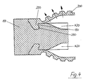
- Figure 4 shows the first embodiment of the membrane filter plate according to the invention, wherein the pressure chamber 420 is pressurized.
- the state shown in Figure 4 occurs at a Unfortunately, more frequently occurring incorrect operation, in which the filter press is not in one Filter state is and the back plate 300 shown in Figure 3 already from the membrane filter plate is lifted, but the pressure chamber 420 is still pressurized.
- the pressure exerted on the membrane 200 pressure indicated by arrows, is on the Fastening strip 220 of the diaphragm 200 exerted a torque which is the outer wall 224 continues to press down.
- the torque is thus aligned so that at best a Circular movement is supported in the operating position.
- a circular motion that is about to release the fastening strip 220 would be necessary from the mounting groove 120 is reliable prevented.
- the locking projection 230 of the fastening strip 220 is in a position under the locking projection 130 and thus forced into an undercut position, so that a release of the fastening strip 220 and the membrane 200 of the support plate 100
- Figure 5 shows a second embodiment of a membrane filter plate according to the invention, the is formed in principle similar to the first embodiment. Same or similar Elements are therefore provided with identical reference numerals.
- the mounting groove 120 also has a bottom 122, an outer wall 124, an inner Wall 128 and a locking projection 130 with a lower surface 132.
- the lower surface 132 of the locking projection 130 also has a pitch here, which is less than the slope the outer wall 124. In contrast to the outer wall 124 of the first embodiment the pitch is larger in the second embodiment and is opposite to the Plate level about 80%.
- the attachment groove 120 at the upper part of the outer wall 124 a latching projection 140 on.
- the membrane 200 has a fastening strip 220 with a complementary outer contour on, with a bottom 222, an outer wall 224, an inner wall 228 and a locking projection 230 having an area 232 whose pitch is less than the pitch of the outer Wall 224. Further, the fastening strip 220 has a latching groove 240, which in the latching position interacts with the latch projection 140 of the mounting groove 120.
- the fastening strip 220 has a recess 242, so that the illustrated in Figure 5 left portion of the fastening strip 220 are pressed flexibly into the recess can, so that the fastening strip 220 in the operating position in the mounting groove 120 can be screwed.
- FIG. 6 shows the second embodiment of the membrane filter plate according to the invention a carrier plate 100 into which two membranes 200, 202 are inserted.
- the latching groove 240 the fastening strip 220 is located with the latching projection 140 of the fastening groove 120 in engagement, so that the fastening strip 220 against unscrewing from the mounting groove 120 is secured.
- This embodiment thus comprises a further securing device against unscrewing the fastening strip 220 from the mounting groove 120th
- the latching groove 240 comprehensive area of the fastening strip 220 in the recess 242 are pressed so that the latching groove 240 in the rotational movement of the latching projection 140 of the mounting groove can be passed.
- This force can, for example be performed by a tool between the support plate 100 and Membrane 200 is pressed so that the outer region of the fastening strip 220 in the Recess 242 is pressed.
- an unlocking opening 160 (shown in dashed lines) is introduced into the carrier plate 100, through which a tool can be inserted, which is the outer area of the fastening strip 220 in the recess 242 of the fastening strip for unlocking and subsequent Unscrew the fastening strip 220 can be pressed.
- Such unlocking openings 160 can be distributed at regular intervals along the mounting bar 220 are introduced into the carrier plate 100.
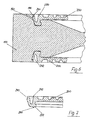
- FIGS. 7 to 10 show further embodiments of the membrane according to the invention 200, which are all provided with a seal or device for receiving a seal exhibit.
- the membrane 200 shown in Figure 7 which is substantially identical is formed with the membrane 200 shown in Figures 5 and 6.
- the fastening strip However, 220 has a sealing lip 260 extending from the bottom 222 of the fastening strip 220 extends and is bent inwards to the pressure side.
- the "print side” is the side where increased pressure occurs or is expected.
- the gap between mounting strip 220, the membrane 200 and the support plate 100 leads into the Pressure chamber 420 of the membrane filter plate, in which the highest pressures occur during operation.
- the sealing lip 260 is integral with the mounting strip 220 and the entire membrane 200 made of polypropylene.
- FIG. 8 shows a further embodiment of the membrane 200 according to the invention, wherein a fastening strip 220 is provided with a multiple sealing lip 262 which extends both extends inwards as well as outwards, so that increased tightness in all directions is guaranteed.
- This multiple sealing lip 262 is also integral with the membrane formed and the entire component is made of polypropylene.
- FIG. 9 shows a further embodiment of the membrane 200 according to the invention, which has a sealing element 264 in its bottom area.
- the sealing element 264 is made made of a thermoplastic elastomer, here rubber, directly on the polypropylene existing fastening strip 220 is cast, so that it is also a one-piece Component is so that when using the membrane 200 in the support plate 100 no additional Step is required to insert a seal.
- FIG. 10 shows a further embodiment of a membrane 200 according to the invention, which is shown in FIG essentially formed as the first embodiment of the membrane according to the invention is.
- the fastening strip 220 has a groove 266 for a seal 268 on, which can be inserted into the groove.
- the seal 268 is also made of rubber here, while the membrane 200 and the fastening strip 220 made of polypropylene (PP) are.
- PP polypropylene
Landscapes
- Chemical & Material Sciences (AREA)
- Chemical Kinetics & Catalysis (AREA)
- Separation Using Semi-Permeable Membranes (AREA)
Description
- Figur 1
- eine erste Ausführungsform einer erfindungsgemäßen Membranfilterplatte, wobei die Membran nicht in der Trägerplatte eingesetzt ist;
- Figur 2
- die in Figur 1 gezeigte Ausführungsform, wobei die Membran in einer Zwischenposition beim Einsetzen in die Trägerplatte dargestellt ist;
- Figur 3
- eine erfindungsgemäße Membranfilterplatte mit zwei eingesetzten Membranen und einer Gegenplatte;
- Figur 4
- die erste Ausführungsform der erfindungsgemäßen Membranfilterplatte, wobei zwei Membranen in die Trägerplatte eingesetzt sind und die Druckräume mit Druck beaufschlagt sind;
- Figur 5
- eine zweite Ausführungsform einer erfindungsgemäßen Membranfilterplatte in dem in Figur 1 dargestellten Zustand;
- Figur 6
- die in Figur 5 dargestellte zweite Ausführungsform der erfindungsgemäßen Membranfilterplatte mit zwei eingesetzten Membranen;
- Figur 7
- eine dritte Ausführungsform einer erfindungsgemäßen Membran;
- Figur 8
- eine vierte Ausführungsform einer erfindungsgemäßen Membran;
- Figur 9
- eine fünfte Ausführungsform einer erfindungsgemäßen Membran;
- Figur 10
- eine sechste Ausführungsform einer erfindungsgemäßen Membran.
Claims (21)
- Membranfilterplatte für eine Filterpresse mitdadurch gekennzeichnet, daßeiner Trägerplatte (100),wenigstens einer an einer Seite der Trägerplatte (100) angeordneten Membran (200, 202),wobei die Membran (200, 202) an ihren Randbereichen eine Befestigungsleiste (220) aufweist unddie Trägerplatte (100) eine Befestigungsnut (120) aufweist, in die die Befestigungsleiste (220) der Membran (200) in eine Betriebsposition einsetzbar ist,so daß die Membran (200, 202) lösbar an der Trägerplatte (100) befestigbar ist,wobei die Befestigungsleiste (220) auf einer inneren Seite einen Rastvorsprung (230) aufweist, der sich nach innen, in Richtung auf einen Druckraum (420) erstreckt und in der Betriebsposition einen komplementären Rastvorsprung (130) auf der inneren Seite der Befestigungsnut (120) der Trägerplatte hinterschneidet, der sich nach außen erstreckt.die Außenkontur (222, 224, 226, 228, 230, 232) der Befestigungsleiste (220) der Membran (200, 202) im wesentlichen der Innenkontur (122, 124, 126, 128, 130, 132) der Befestigungsnut (120) der Trägerplatte (100) entspricht unddie Außenkontur (222, 224, 226, 228, 230, 232) der Befestigungsleiste (220) und die Innenkontur (122, 124, 126, 128, 130, 132) der Befestigungsnut (120) so ausgebildet sind, daß die in die Befestigungsnut (120) eingesetzte und sich in der Betriebsposition befindliche Befestigungsleiste (220) nur mittels einer zu einer Plattenebene (150) der Trägerplatte (100) im wesentlichen senkrechten Drehbewegung lösbar ist, bei der eine äußere obere Randlinie der Befestigungsleiste (220) eine gekrümmte Bahn beschreibt, die von ihrer Betriebsposition in der Befestigungsnut (120) zumindest teilweise nach oben und innen in Richtung auf einen Druckraum (420) verläuft, und die nicht eingesetzte Befe-Befestigungsleiste nur durch eine entgegengesetzte Drehbewegung in ihre Betriebsposition in der Befestigungsnut (120) einsetzbar ist,
- Membranfilterplatte nach Anspruch 1 dadurch gekennzeichnet, daß ein Boden (122) der Befestigungsnut (120) und ein Boden (222) der Befestigungsleiste (220) im wesentlichen eben ist und sich im wesentlichen parallel zu einer Plattenebene (150) der Trägerplatte (100) erstreckt.
- Membranfilterplatte nach einem der Ansprüche 1 bis 2, dadurch gekennzeichnet, daß eine äußere Wand (124) der Befestigungsnut (120) und eine äußere Wand (224) der Befestigungsleiste (220) sich vom jeweiligen Boden (122, 222) nach oben und nach außen erstreckt.
- Membranfilterplatte nach Anspruch 3, dadurch gekennzeichnet, daß die äußere Wand (124) der Befestigungsnut (120) und die äußere Wand (224) der Befestigungsleiste (220), wenn sich diese in der Betriebsposition befindet, mit der Plattenebene (150) der Trägerplatte (100) einen Außenwinkel von 30° bis 80°, bevorzugt von 55° bis 65° einschließt.
- Membranfilterplatte nach einem der Ansprüche 3 bis 4, dadurch gekennzeichnet, daß die äußere Wand (124) der Befestigungsnut (120) und die äußere Wand (224) der Befestigungsleiste (220) in einem oberen Bereich einen senkrecht zur Plattenebene (150) oder schräg nach oben und innen verlaufenden Abschlußbereich (126, 226) aufweisen.
- Membranfilterplatte nach Anspruch 5, dadurch gekennzeichnet, daß sich der jeweilige Abschlußbereich (126, 226) über 15% bis 35% der Tiefe der Befestigungsnut (120), bevorzugt über 20% bis 25% der Tiefe der Befestigungsnut (120) erstreckt.
- Membranfilterplatte nach einem der Ansprüche 1 bis 6, dadurch gekennzeichnet, daß die Befestigungsnut (120) und die Befestigungsleiste (220) jeweils einen Rast-Vorsprung (130, 230) aufweisen, wobei jeder Rast-Vorsprung (130, 230) eine untere Fläche (132, 232) aufweist, deren Steigung bezüglich der Plattenebene (150) geringer ist als die Steigung der jeweiligen äußeren Wand (124, 224) der Befestigungsnut (120) und der Befestigungsleiste (120).
- Membranfilterplatte nach einem der Ansprüche 1 bis 7, dadurch gekennzeichnet, daß ein äußerer Wandbereich der Befestigungsnut (120) einen nach innen ragenden Einrast-Vorsprung (140) aufweist und der obere Teil eines äußeren Wandbereichs der Befestigungsleiste (220) eine nach innen ragenden Einrast-Nut (240) aufweist, die komplementär zu dem Einrast-Vorsprung (140) der Befestigungsnut ausgebildet ist und in der Betriebsposition mit diesem wechselwirkt.
- Membranfilterplatte nach Anspruch 8, dadurch gekennzeichnet, daß die Befestigungsleiste (220) eine nach oben offene Ausnehmung aufweist, so daß der mit der Einrast-Nut (140) versehene äußere Wandbereich flexibel nach innen eindrückbar ist, so daß der wechselwirkende Eingriff lösbar ist.
- Membranfilterplatte nach einem der Ansprüche 1 bis 9, dadurch gekennzeichnet, daß die Membran (200, 202) und/oder die Trägerplatte (100) und/oder nur die Befestigungsleiste (220) aus Kunststoff bestehen, insbesondere aus Polypropylen (PP).
- Membranfilterplatte nach einem der Ansprüche 1 bis 10, dadurch gekennzeichnet, daß die Befestigungsleiste (220) und/oder die Befestigungsnut (120) eine Nut (266) für eine Dichtung (268) aufweisen.
- Membranfilterplatte nach einem der Ansprüche 1 bis 11, dadurch gekennzeichnet, daß die Befestigungsleiste (220) und/oder die Befestigungsnut (120) mit einer Dichtung (260, 262, 264) ausgestattet sind.
- Membranfilterplatte nach einem der Ansprüche 1 bis 11, dadurch gekennzeichnet, daß die Membran (200) und/oder die Trägerplatte (100) mit einer Dichtung ausgestattet ist, wobei die Dichtung in Richtung auf eine Druckseite der Befestigungsleiste (220) bzw. der Befestigungsnut (120) vorgelagert angeordnet ist.
- Membranfilterplatte nach Anspruch 12 oder 13, dadurch gekennzeichnet, daß die Dichtung (260, 262, 264) einstückig mit der Befestigungsleiste (220) und/oder der Befestigungsnut (120) ausgebildet ist.
- Membranfilterplatte nach einem der Ansprüche 12 bis 14, dadurch gekennzeichnet, daß die Befestigungsleiste (220) und/oder die Befestigungsnut (120) aus Polypropylen (PP) hergestellt sind und die Dichtung (264) aus einem thermoplastischen Elastomer, insbesondere aus Gummi, besteht.
- Membranfilterplatte nach einem der Ansprüche 14 bis 15, dadurch gekennzeichnet, daß die Dichtung an die Befestigungsleiste (220) und/oder der Befestigungsnut (120) angegossen ist.
- Membranfilterplatte nach einem der Ansprüche 12 bis 16, dadurch gekennzeichnet, daß die Dichtung (260, 262) in Form einer Dichtlippe ausgebildet ist.
- Membranfilterplatte nach Anspruch 17, dadurch gekennzeichnet, daß die Dichtlippe (260) in Richtung auf die Druckseite hin gebogen ist.
- Membranfilterplatte nach einem der Ansprüche 17 bis 18, dadurch gekennzeichnet, daß eine Mehrfach-Dichtlippe (262) vorgesehen ist.
- Membran für eine Membranfilterplatte für eine Filterpresse, wobei die Membran an ihren Randbereichen eine Befestigungsleiste aufweist, die in eine Befestigungsnut einer zugehörigen Trägerplatte in eine Betriebsposition einsetzbar ist, so daß die Membran lösbar an der Trägerplatte befestigbar ist,
dadurch gekennzeichnet, daßwobei die Befestigungsleiste (220) auf einer inneren Seite einen Rastvorsprung (230) aufweist, der sich nach innen, in Richtung auf einen Druckraum (420) erstreckt und in der Betriebsposition einen komplementären Rastvorsprung (130) auf der inneren Seite der Befestigungsnut (120) der Trägerplatte hinterschneidet, der sich nach außen erstreckt.die Außenkontur (222, 224, 226, 228, 230, 232) der Befestigungsleiste (220) der Membran (200, 202) im wesentlichen einer Innenkontur (122, 124, 126, 128, 130, 132) der Befestigungsnut (120) der zugehörigen Trägerplatte (100) entspricht unddie Außenkontur (222, 224, 226, 228, 230, 232) der Befestigungsleiste (220) so ausgebildet ist, daß die in die Befestigungsnut (120) eingesetzte und sich in der Betriebsposition befindliche Befestigungsleiste (220) nur mittels einer zu einer Plattenebene (150) der Trägerplatte (100) im wesentlichen senkrechten Drehbewegung lösbar ist, bei der eine äußere obere Randlinie der Befestigungsleiste (220) eine gekrümmte Bahn beschreibt, die von ihrer Betriebsposition in der Befestigungsnut (120) zumindest teilweise nach oben und innen in Richtung auf einen Druckraum (420) verläuft, und die nicht eingesetzte Befestigungsleiste nur durch eine entgegengesetzte Drehbewegung in ihre Betriebsposition in der Befestigungsnut (120) einsetzbar ist, - Trägerplatte für eine Membranfilterplatte für eine Filterpresse, wobei die Trägerplatte eine Befestigungsnut aufweist, in die eine Befestigungsleiste einer zugehörigen Membran nach Anspruch 20 in eine Betriebsposition einsetzbar ist, so daß die Membran lösbar an der Trägerplatte befestigbar ist,
dadurch gekennzeichnet, daßwobei die Innenkontur einen Rastvorsprung (130) auf der inneren Seite der Befestigungsnut (120) aufweist, der sich nach außen, in Richtung von einem Druckraum weg, erstreckt und bei einer in der Betriebsposition eingesetzten zugehörigen Membran einen komplementären Rastvorsprung (230) auf der inneren Seite der Befestigungsleiste (220) der Membran hinterschneidet, der sich nach innen erstreckt.die Innnenkontur (122, 124, 126, 128, 130, 132) der Befestigungsnut (120) im wesentlichen einer Außenkontur (222, 224, 226, 228, 230, 232) einer Befestigungsleiste (220) einer zugehörigen Membran (200, 210) entspricht unddie Innenkontur (122, 124, 126, 128, 130, 132) der Befestigungsnut (120) so ausgebildet ist, daß die in die Befestigungsnut (120) eingesetzte und sich in der Betriebsposition befindliche Befestigungsleiste (220) nur mittels einer Drehbewegung lösbar ist, bei der eine äußere obere Randlinie der Befestigungsleiste (220) eine gekrümmte Bahn beschreibt, die von ihrer Betriebsposition in der Befestigungsnut (120) zumindest teilweise nach oben und innen in Richtung auf einen Druckraum (420) verläuft, und die nicht eingesetzte Befestigungsleiste nur durch eine entgegengesetzte Drehbewegung in ihre Betriebsposition in der Befestigungsnut (120) einsetzbar ist,
Applications Claiming Priority (2)
| Application Number | Priority Date | Filing Date | Title |
|---|---|---|---|
| DE10024725A DE10024725C2 (de) | 2000-05-19 | 2000-05-19 | Membranfilterplatte für eine Filterpresse sowie Trägerplatte und Membran für eine solche Membranfilterplatte |
| DE10024725 | 2000-05-19 |
Publications (2)
| Publication Number | Publication Date |
|---|---|
| EP1163943A1 EP1163943A1 (de) | 2001-12-19 |
| EP1163943B1 true EP1163943B1 (de) | 2004-01-21 |
Family
ID=7642747
Family Applications (1)
| Application Number | Title | Priority Date | Filing Date |
|---|---|---|---|
| EP01111354A Expired - Lifetime EP1163943B1 (de) | 2000-05-19 | 2001-05-09 | Membranfilterplatte für eine Filterpresse sowie Trägerplatte und Membran für eine solche Membranfilterplatte |
Country Status (3)
| Country | Link |
|---|---|
| EP (1) | EP1163943B1 (de) |
| DE (2) | DE10024725C2 (de) |
| MY (1) | MY122816A (de) |
Families Citing this family (5)
| Publication number | Priority date | Publication date | Assignee | Title |
|---|---|---|---|---|
| EP2213354B1 (de) | 2009-01-14 | 2010-12-01 | Sefar AG | Randstreifen zum Zurückhalten eines Filtertuchs, Filterelement und Rahmenelement zur Aufnahme eines Randstreifens |
| DE102009020317A1 (de) * | 2009-05-07 | 2010-11-18 | Klinkau Gmbh + Co. | Membranträger und Membran für eine Filterpresse |
| CA2867339A1 (en) * | 2012-04-19 | 2013-10-24 | Outotec (Finland) Oy | Method for sealing a filter chamber and filter device |
| AU2020442210A1 (en) * | 2020-04-17 | 2022-08-11 | Metso Finland Oy | A filter diaphragm for a horizontal plate and frame -type filter, such as a tower press |
| DE212020000821U1 (de) * | 2020-04-17 | 2023-01-04 | Metso Outotec Finland Oy | Eine Filtermembran, ein Plattenrahmen, eine Plattenrahmenanordnung, ein Routing- oder Fräswerkzeugsatz und eine horizontale Filterpresse |
Family Cites Families (7)
| Publication number | Priority date | Publication date | Assignee | Title |
|---|---|---|---|---|
| DE2322044C2 (de) * | 1973-05-02 | 1983-02-03 | Eberhard Hoesch & Söhne GmbH & Co, 5160 Düren | Preßmembran für Membranplatten |
| DE8419759U1 (de) * | 1984-07-02 | 1984-10-31 | Hansen-BTR-GmbH, 3000 Hannover | Membranfilterplatte |
| DE4119166C2 (de) * | 1991-06-11 | 1998-10-01 | Lenser Kunststoff Preswerk Gmb | Filterelement für eine Filterpresse |
| DE9216298U1 (de) * | 1992-12-01 | 1993-02-11 | Rittershaus & Blecher Gmbh, 5600 Wuppertal | Membranfilterplatte |
| DE4325235C2 (de) * | 1993-07-28 | 1995-08-31 | Junker Filter Gmbh | Filterelement für ein Kammer-, Membranfilter oder dergleichen sowie Verfahren zu seiner Herstellung |
| DE4415274C2 (de) * | 1994-04-30 | 1998-04-30 | Jv Kunststoffwerk | Filterplatte für eine Plattenfilterpresse |
| DE4419865C1 (de) * | 1994-06-07 | 1995-06-08 | Lenser Kunststoff Preswerk Gmb | Membranfilterplatte für eine Filterpresse |
-
2000
- 2000-05-19 DE DE10024725A patent/DE10024725C2/de not_active Expired - Lifetime
-
2001
- 2001-05-09 EP EP01111354A patent/EP1163943B1/de not_active Expired - Lifetime
- 2001-05-09 DE DE50101346T patent/DE50101346D1/de not_active Expired - Lifetime
- 2001-05-21 MY MYPI20012388 patent/MY122816A/en unknown
Also Published As
| Publication number | Publication date |
|---|---|
| MY122816A (en) | 2006-05-31 |
| EP1163943A1 (de) | 2001-12-19 |
| DE10024725A1 (de) | 2001-11-22 |
| DE10024725C2 (de) | 2002-11-21 |
| DE50101346D1 (de) | 2004-02-26 |
Similar Documents
| Publication | Publication Date | Title |
|---|---|---|
| DE3220487C2 (de) | Filterplatte | |
| EP2123497B2 (de) | Profilelement zum Verbinden einer Fahrzeugscheibe mit einem Wasserkasten | |
| EP0742762B2 (de) | Verfahren für die herstellung und den einbau einer glasscheibe mit rahmen, insbesondere an einem fahrzeugteil | |
| EP1649920B1 (de) | Luftfilter | |
| DE112006003021T5 (de) | Fluidfilter mit offenem Strömungsende und austauschbarer Kartusche | |
| DE19856520A1 (de) | Gehäuse, insbesondere Filtergehäuse mit Filtereinsatz | |
| DE10221061B4 (de) | Membran, Membranplatte und Plattenpaket für eine Filterpresse | |
| EP3523004B1 (de) | Anordnung einer filterplatte und eines anbauteils | |
| DE4119166C2 (de) | Filterelement für eine Filterpresse | |
| EP0556186B1 (de) | Membranplatte für plattenfilterpressen | |
| DE3520653A1 (de) | Membranplatte fuer plattenfilterpressen | |
| EP1163943B1 (de) | Membranfilterplatte für eine Filterpresse sowie Trägerplatte und Membran für eine solche Membranfilterplatte | |
| EP0247288A2 (de) | Filterpresse | |
| EP0687492B1 (de) | Membranfilterplatte für eine Filterpresse | |
| EP0357015B1 (de) | Membranfilterplatte für Filterpressen | |
| WO2004043569A2 (de) | Membranfilterpresse | |
| EP2427252B1 (de) | Membranträger für eine filterpresse | |
| CH626265A5 (de) | ||
| EP0827766A1 (de) | Pressmembran für eine Membranplatte einer Plattenfilterpresse | |
| EP0208076A2 (de) | Membranfilterplatte mit Trägerplatte und Dichtrand | |
| DE10024722C2 (de) | Membranfilterplatte für eine Filterpresse sowie Trägerplatte und Membran für eine solche Membranfilterplatte | |
| DE102023115044B3 (de) | Flexible Endkappe für keramische Flachfilter | |
| EP4585463B1 (de) | Monomaterielle fussmattenbefestigung | |
| DE19534468A1 (de) | In einem Gehäuse festlegbare Patronenfiltereinheit | |
| DE102024105104A1 (de) | Ein Adapterelement, eine Filterpatrone, eine Luftfiltervorrichtung, ein Verfahren zum Ersetzen einer Filterpatrone einer Luftfiltervorrichtung durch eine andere Filterpatrone |
Legal Events
| Date | Code | Title | Description |
|---|---|---|---|
| PUAI | Public reference made under article 153(3) epc to a published international application that has entered the european phase |
Free format text: ORIGINAL CODE: 0009012 |
|
| AK | Designated contracting states |
Kind code of ref document: A1 Designated state(s): DE FR GB IT Kind code of ref document: A1 Designated state(s): AT BE CH CY DE DK ES FI FR GB GR IE IT LI LU MC NL PT SE TR |
|
| AX | Request for extension of the european patent |
Free format text: AL;LT;LV;MK;RO;SI |
|
| 17P | Request for examination filed |
Effective date: 20011128 |
|
| AKX | Designation fees paid |
Free format text: DE FR GB IT |
|
| 17Q | First examination report despatched |
Effective date: 20021220 |
|
| GRAP | Despatch of communication of intention to grant a patent |
Free format text: ORIGINAL CODE: EPIDOSNIGR1 |
|
| GRAS | Grant fee paid |
Free format text: ORIGINAL CODE: EPIDOSNIGR3 |
|
| GRAA | (expected) grant |
Free format text: ORIGINAL CODE: 0009210 |
|
| AK | Designated contracting states |
Kind code of ref document: B1 Designated state(s): DE FR GB IT |
|
| REG | Reference to a national code |
Ref country code: GB Ref legal event code: FG4D Free format text: NOT ENGLISH |
|
| GBT | Gb: translation of ep patent filed (gb section 77(6)(a)/1977) |
Effective date: 20040121 |
|
| REG | Reference to a national code |
Ref country code: IE Ref legal event code: FG4D Free format text: GERMAN |
|
| REF | Corresponds to: |
Ref document number: 50101346 Country of ref document: DE Date of ref document: 20040226 Kind code of ref document: P |
|
| REG | Reference to a national code |
Ref country code: IE Ref legal event code: FD4D |
|
| ET | Fr: translation filed | ||
| PLBE | No opposition filed within time limit |
Free format text: ORIGINAL CODE: 0009261 |
|
| STAA | Information on the status of an ep patent application or granted ep patent |
Free format text: STATUS: NO OPPOSITION FILED WITHIN TIME LIMIT |
|
| 26N | No opposition filed |
Effective date: 20041022 |
|
| REG | Reference to a national code |
Ref country code: DE Ref legal event code: R082 Ref document number: 50101346 Country of ref document: DE Representative=s name: BOEHMERT & BOEHMERT, DE |
|
| REG | Reference to a national code |
Ref country code: DE Ref legal event code: R081 Ref document number: 50101346 Country of ref document: DE Owner name: KLINKAU GMBH + CO. KG, DE Free format text: FORMER OWNER: KLINKAU GMBH + CO., 87616 MARKTOBERDORF, DE Effective date: 20140722 Ref country code: DE Ref legal event code: R082 Ref document number: 50101346 Country of ref document: DE Representative=s name: BOEHMERT & BOEHMERT ANWALTSPARTNERSCHAFT MBB -, DE Effective date: 20140722 |
|
| REG | Reference to a national code |
Ref country code: FR Ref legal event code: PLFP Year of fee payment: 16 |
|
| REG | Reference to a national code |
Ref country code: FR Ref legal event code: PLFP Year of fee payment: 17 |
|
| REG | Reference to a national code |
Ref country code: FR Ref legal event code: PLFP Year of fee payment: 18 |
|
| PGFP | Annual fee paid to national office [announced via postgrant information from national office to epo] |
Ref country code: FR Payment date: 20200414 Year of fee payment: 20 Ref country code: DE Payment date: 20200529 Year of fee payment: 20 |
|
| PGFP | Annual fee paid to national office [announced via postgrant information from national office to epo] |
Ref country code: IT Payment date: 20200414 Year of fee payment: 20 Ref country code: GB Payment date: 20200429 Year of fee payment: 20 |
|
| REG | Reference to a national code |
Ref country code: DE Ref legal event code: R071 Ref document number: 50101346 Country of ref document: DE |
|
| REG | Reference to a national code |
Ref country code: GB Ref legal event code: PE20 Expiry date: 20210508 |
|
| PG25 | Lapsed in a contracting state [announced via postgrant information from national office to epo] |
Ref country code: GB Free format text: LAPSE BECAUSE OF EXPIRATION OF PROTECTION Effective date: 20210508 |