EP1163973B1 - Table pour une machine d'usinage - Google Patents
Table pour une machine d'usinage Download PDFInfo
- Publication number
- EP1163973B1 EP1163973B1 EP01113913A EP01113913A EP1163973B1 EP 1163973 B1 EP1163973 B1 EP 1163973B1 EP 01113913 A EP01113913 A EP 01113913A EP 01113913 A EP01113913 A EP 01113913A EP 1163973 B1 EP1163973 B1 EP 1163973B1
- Authority
- EP
- European Patent Office
- Prior art keywords
- machine table
- vacuum
- workpiece
- channel
- machine
- Prior art date
- Legal status (The legal status is an assumption and is not a legal conclusion. Google has not performed a legal analysis and makes no representation as to the accuracy of the status listed.)
- Expired - Lifetime
Links
Images


Classifications
-
- B—PERFORMING OPERATIONS; TRANSPORTING
- B23—MACHINE TOOLS; METAL-WORKING NOT OTHERWISE PROVIDED FOR
- B23Q—DETAILS, COMPONENTS, OR ACCESSORIES FOR MACHINE TOOLS, e.g. ARRANGEMENTS FOR COPYING OR CONTROLLING; MACHINE TOOLS IN GENERAL CHARACTERISED BY THE CONSTRUCTION OF PARTICULAR DETAILS OR COMPONENTS; COMBINATIONS OR ASSOCIATIONS OF METAL-WORKING MACHINES, NOT DIRECTED TO A PARTICULAR RESULT
- B23Q1/00—Members which are comprised in the general build-up of a form of machine, particularly relatively large fixed members
- B23Q1/25—Movable or adjustable work or tool supports
-
- B—PERFORMING OPERATIONS; TRANSPORTING
- B23—MACHINE TOOLS; METAL-WORKING NOT OTHERWISE PROVIDED FOR
- B23Q—DETAILS, COMPONENTS, OR ACCESSORIES FOR MACHINE TOOLS, e.g. ARRANGEMENTS FOR COPYING OR CONTROLLING; MACHINE TOOLS IN GENERAL CHARACTERISED BY THE CONSTRUCTION OF PARTICULAR DETAILS OR COMPONENTS; COMBINATIONS OR ASSOCIATIONS OF METAL-WORKING MACHINES, NOT DIRECTED TO A PARTICULAR RESULT
- B23Q1/00—Members which are comprised in the general build-up of a form of machine, particularly relatively large fixed members
- B23Q1/03—Stationary work or tool supports
- B23Q1/032—Stationary work or tool supports characterised by properties of the support surface
-
- B—PERFORMING OPERATIONS; TRANSPORTING
- B25—HAND TOOLS; PORTABLE POWER-DRIVEN TOOLS; MANIPULATORS
- B25B—TOOLS OR BENCH DEVICES NOT OTHERWISE PROVIDED FOR, FOR FASTENING, CONNECTING, DISENGAGING, OR HOLDING
- B25B11/00—Work holders not covered by any preceding group in the subclass, e.g. magnetic work holders, vacuum work holders
- B25B11/005—Vacuum work holders
Definitions
- the invention relates to a machine table for a processing machine with the features of the preamble of claim 1, such. from EP-A-650 800 known.
- a workpiece to be machined for example, made of wood, metal, plastic or glass directly to edit it with the processing machine, such as a router or the like.
- working aids on the machine table, on which then the workpiece to be machined is taken, or which in turn serve to edit the workpiece.
- suitable means are provided on the upper side of the machine table, which cooperate with the workpiece or the working tool and thus allow a tightening thereof.
- Such means may for example comprise a grid-groove structure which is introduced into the table surface and which is connected to a vacuum source, so that a negative pressure can be introduced into the structure.
- Upper inserted into the grooves sealing cords can be created as a delimited vacuum space on which the workpiece is placed and so can be sucked.
- magnetic surfaces are known on which working aids, which have a metallic holding portion, placed and can be held. These are just a few known clamping techniques that can be used to hold workpieces or work aids to a machine table.
- Each machine table is designed or constructed for a particular clamping technique, that is, the worker can only use a clamping technique on the table associated with a processing machine.
- This is accompanied by the fact that when changing the workpieces to be machined, for example, in the context of mass production selected for the workpiece A device of the machine table on which, for example, appropriate working aids are placed in the form of vacuum suction, placed in their arrangement according to the shape of the workpiece A. must be changed in order to set up the table according to the shape and requirements of the subsequently machined workpiece B. This is expensive and time consuming.
- a machine table for a processing machine for processing wood is known, with which at least one workpiece to be machined or at least one working aid can be accommodated, and which has at least one rotatably mounted about an axis table element, the at least two Turning the table element in a working position has engageable sides on which the workpiece and / or to the working tool can be fastened.
- This work surface includes a plurality of work tables that are adjustable along a horizontal longitudinal axis of said work surface and include means for realizing the retention of a work piece being worked on the work surface.
- a machine tool which has a preferably movable in three axial directions spindle for tool holder.
- the clamping table is pivotable about a pivot axis extending transversely to the axis of rotation of the spindle.
- the clamping table has on both sides of the pivot axis in each case a clamping surface for a workpiece.
- the invention is based on the problem of specifying a more flexible and variably usable machine table.
- the rotatability of the table element according to the invention which has at least two working sides, on which a workpiece or a working aid can be fastened, makes possible a variable and very flexible work.
- On each side of the table corresponding means for holding the workpiece or the working tool of any kind are provided.
- On the respective sides similar holding means or differently operating holding means may be provided.
- the sealing cords on a first side according to the shape of the Insert workpiece A and close the corresponding opening outside of the surrounding of the sealing cords surface vacuum channel openings.
- the sealing cords may or may be placed according to the shape of a workpiece B. In the case of a workpiece change is a immediate change of table side possible without any further facilities would be required.
- the machine table can be used multifunctional by the worker, because it is possible for him to be able to clamp different workpieces with one and the same machine table using different clamping techniques or different holding means and to be able to process these workpieces with one and the same processing machine.
- different machine table-processing machine combinations have hitherto been required, since the variability of the clamping techniques according to the invention was not present on a machine table.
- the table element is designed like a console, wherein a plurality of console-like and mutually parallel table elements are provided on a table frame.
- the table or clamping plane is formed by means of the plurality of table elements, each having a plurality of sides, which can be brought into a corresponding working position.
- a workpiece can at only one table element or across two or more table elements to this be clamped, either directly or with the interposition of appropriate tools such as vacuum suction or the like. Since each table element is rotatably mounted, turning is very space-saving possible in this way, at the same time given the opportunity to form very large table levels.
- the table element may be formed as a large-scale table top.
- only one table element supported on a corresponding table frame is used, which can be pivoted about an axis - which in a conventional rectangular design of the table top preferably extends in its longitudinal direction.
- each console-like table element in cross section may be substantially triangular in shape and have three sides, on which corresponding holding means may be provided. In this case, the worker can choose between three different working pages.
- each table element in cross-section can also be essentially quadrangular and have four sides. Even table elements with more than four sides are conceivable.
- Two-, three- or quadrangular table elements are particularly advantageous if, as may be provided according to the invention, the console-like table elements are slidably mounted on the table frame.
- the slidable mounting that every table element can be arbitrarily positioned close to another, to clamp even smaller workpieces, which are to be clamped using two juxtaposed table elements, easily.
- table elements with two sides which are thus substantially flat and rectangular are formed, when using triangular table elements and when using quadrangular table elements to arrange them directly adjacent to each other, so that it is possible to form a quasi-closed table surface, which allows a complete resting of a workpiece.
- the table elements themselves can be manually displaceable, in addition or alternatively, an automatic displacement can be realized.
- Motorized or pneumatic drives are expediently used for the automatic shifting.
- the automatic shifting is expediently controlled via a central control device.
- the table elements can be locked by means of suitable locking or locking mechanisms.
- a usable displacement mechanism is described for example in the patent application DE 100 23 916, to which reference is expressly made and the disclosure of which is included in the present application.
- the turning of the table or the elements can be done manually and / or automatically, including also corresponding motor or pneumatic drives can be provided, which are controlled by a common central control device.
- the table elements are locked by means of suitable locking or locking means.
- several table elements can be rotatable together by means of a common motor or pneumatic drive, alternatively, the individual table elements can also be rotated separately by means of a separate, each table element associated drive.
- similar and / or differently acting means acting on or cooperating with the workpiece or the working aid may be provided on the sides for holding the workpiece and / or the working auxiliary. If more than two sides are provided on the respective table element, that is to say in the case of a three, four or polygonal design, then of course two or more sides can have identically acting and correspondingly differently acting holding means, which is a concrete design or distribution hereby arbitrarily.
- each table element is modular in so far as it consists of a kind of basic carrier to which one or more plate-shaped Aufsetzieri can be attached to the respective sides. These Aufsetzieri have or form the respective holding means, that is, with each attachment element, a specific clamping technology is realized or arranged on the base support.
- the means may comprise a grid-groove structure by means of which a negative pressure can be applied to the attached workpiece or the working auxiliary.
- This grid-groove structure can either be milled directly into the respective side of the table element, alternatively, this structure may be formed on a plate-shaped attachment element, which in turn fastened to the support of the table element, preferably screwed.
- a further embodiment of the holding means provides these in the form of a groove structure, in particular a T-slot structure, which cooperate with corresponding counterparts which can be inserted into them and are formed on the workpiece or on the working auxiliary for holding them.
- T-shaped grooves can be introduced directly to the table element in the surface, alternatively they can be formed on a mounting plate.
- Hatte Vietnamese working aids are preferably held and braced, for example in the form of separate clamps, a tailstock, a stop or the like.
- the vacuum clamping structure can be brought into the horizontal working position and attached to the vertically extending T-slot structure corresponding stops. This means that corresponding structures can generally also be shared.
- the means may comprise longitudinal rails on which at least one carriage supporting the workpiece or the working aid is displaceable and lockable.
- This cart may, for example, carry a receiving platform for a working aid, for example for vacuum clamping sleeves, which can be attached on the one hand via vacuum on the flat receiving platform and on the other hand can clamp a workpiece on the upper side via negative pressure.
- a vacuum clamping device which can be used for this purpose is described, for example, in German Patent Application DE 197 50 656, to which reference is made in detail and the disclosure content of which is incorporated into the application. If it is a modular table element, the rails are provided on a corresponding mounting plate on which then or the car can be set.
- these may comprise a plurality of intake openings which can be closed by means of valve elements, by means of which a negative pressure can be applied to the attached workpiece or the working aid.
- These suction openings with the integrated valve elements can be provided directly on the table element or on a suitable mounting plate.
- An example of the embodiment of such a holding device is described, for example, in German patent application DE 100 23 323, to which reference is made in detail and the disclosure content of which is incorporated into this application.
- electrovalves are used, which are controlled by a central control device. It is important to make sure that the connecting lines between the controller and the solenoid valves are guided so that they can not be turned off when turning a table element.
- holding means comprise a magnetic plate, in particular a magnetizable via an electromagnet plate.
- appropriate working aids - of course, also to be machined workpieces, which have a corresponding metal insert or the like - are supported on the plate.
- a further alternative of the invention provides that the means comprise a metal plate with a plurality of top side opening channel openings with associated magnetic closure discs, wherein a negative pressure can be placed on the attached workpiece or the working aid via the channel openings.
- the channel openings are closed via the described closure discs and opened as needed, so that the worker can form any desired suction configuration by simply removing or placing the closure discs.
- the means comprise a wooden or plastic plate into which nails, screws or other fastening elements can be introduced.
- the respective attachment element is expediently designed plate-shaped as described, in order to realize the largest possible receiving surface for the workpiece / working aid along the table element.
- Each attachment element is fastened by suitable fastening means on the respective side of the table element, for which purpose expedient fastening screws are used which are screwed into corresponding threaded receivers on the base carrier.
- Each attachment element thus forms an adapter for a specific fastening or clamping technique.
- At least one Vacuum channel provided over the at least one side of those means, can be supplied via the negative pressure to the workpiece or the working tool, can be supplied with negative pressure.
- an external vacuum source is connected, the channel itself is guided so that wherever the vacuum is to be delivered to the workpiece, corresponding openings are provided.
- the table element has a modular construction, it is expedient if a plurality of channel bores communicating with the integrated vacuum channel open at the respective side, of which at least one part can be connected to corresponding channel bores of the respective attachment element.
- the channel bores are arranged such that they are automatically connected when placing a plate-shaped Aufsetzelements with corresponding holes formed there to transmit the negative pressure to the Aufsetzelement.
- a corresponding channel network consisting of a multiplicity of channel grooves can also be provided on the underside of the attachment element. If such a groove covers a corresponding carrier-side channel bore, the entire channel network is automatically pressurized with negative pressure.
- the carrier-side provided channel holes are, when a landing element with a holding technique that does not work with negative pressure, is placed, simply sealed from the bottom of the Aufsetzelements.
- each Aufsetzelements may be provided on the underside of each Aufsetzelements, that is, the underside of the Aufsetzelements is slightly spaced from the top of the base support, but the Aufsetzelement itself sits on the edge completely tight on the support.
- At least one vacuum channel is provided below each side of the table element, which opens at the respective side via channel bores in order to create the possibility of being able to attach a mounting plate with negative pressure holding means on any desired side.
- a negative pressure channel assigned to a side only reaches and automatically reaches it the position in which the respective side is in its working position, with an external vacuum source is connectable. If, according to this embodiment, a page is rotated into its working position, the coupling of a negative pressure channel assigned to the page with an external negative pressure source is automatically realized.
- one or more locking elements can be provided for locking the table element in the respective position.
- locking bolts which engage mechanically or electrically controlled in corresponding recesses, conceivable.
- a locking element is simultaneously formed as a connecting element between the vacuum channel and the vacuum element connectable to the locking element.
- a correspondingly formed locking element engages, when it snaps into the detent position, against a vacuum channel and connects it simultaneously with the vacuum source.
- This arresting element thus has a locking and a channel-connecting function.
- a plate which closes the negative pressure channel (s) and possibly the one or more compressed air channels, at the suitable connecting means for connecting a vacuum channel or a compressed air channel with the respective source and / or a locking element are provided.
- the table element or its base support itself is preferably pressed in the manner of an extruded profile and therefore open on both sides, where it is closed by a corresponding closure plate and the corresponding channels are sealed. At one of these plates all necessary connections are expediently provided.
- the or each particular console-like table element consists of a plurality of successively arranged table element sections each having at least two sides, which are rotatable and mutually lockable about a common axis separately.
- the separately rotatable and lockable table element sections can in turn carry any different clamping techniques on the respective sides, so that within a table element level different clamping techniques can be rotated at different positions along the table element in working position, which further increases the flexibility.
- the table element sections may be manually and / or mechanically rotatable. For locking serve purposeful locking couplings, that is, the sections engage with each other when they are in the respective end position in which the respective sides of the sections are parallel to each other.
- each table element section should have at least one vacuum and / or at least one compressed air channel, wherein at least the channels of two juxtaposed table element sections, which are in the upper working position, are coupled to each other, so that via a central terminal as already described above all resources also can be looped between the table element sections.
- the channels located in the working position can be coupled to each other, it is expedient if the channels of two juxtaposed table element sections, which are in the region of a not in the upper working position side are coupled to each other, for example the compressed air from one side, not the is turned upward, remove and supply them to a top-mounted work tool.
- At least one table element section is removable from the composite, so that a total of a modular system is realized, in which the individual table element sections can be selectively used or removed.
- the table element sections can be releasably placed on a central, running in the axis of rotation support, for example screwed, plugged, clamped or held by magnetic force. After attaching the respective section, it can be rotated by driving the carrier.
- An expedient alternative to the invention provides that the at least one table element section can be completely removed from the composite, so that a gap arises between two table element sections into which a third object can be inserted.
- a third object for example a workpiece to be machined, can be stretched and driven in rotation between two table element sections, so that it is possible to machine the workpiece by turning, turning, etc.
- the drive of the workpiece takes place via one of the outer table elements, the table element located at the other end forms the running opposite side.
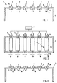
- the machine table 1 shows a machine table 1 according to the invention of a first embodiment as a schematic diagram.
- the machine table 1 consists of a table frame 2, to which a plurality of table elements 3 are attached. These table elements are, as shown in Fig. 1, rotatably mounted about the respective axis of rotation 4, as indicated by the respective arrow A.
- rotatably mounted table elements 3 are in the example shown corresponding motors 6 are provided, which are connected via corresponding connecting lines with a central control device 7.
- Each table element has four sides I, II, III, IV, on which there are corresponding holding means for holding a workpiece and / or working tool, which will be discussed with reference to FIGS. 5 and 7.
- all table elements 3 along the horizontal support 8 of the table frame 2 are displaceable, as indicated in Fig. 2 by the arrows B.
- the horizontal displacement is advantageously carried out automatically controlled by the control device 7, wherein, for example, a displacement technique as described in the patent application DE 100 23 916 can be used. This makes it possible to space the table elements 3 arbitrarily close or away from each other so as to form any table top configuration.
- the quadrangular design of the table elements 3 shown in FIGS. 1 and 2 allows them to be positioned directly adjacent to one another so that a closed table top can be formed, as it were.
- the table elements 9 shown in FIG. 3 have three sides I, II, III, on which corresponding holding means are provided.
- a common rotation about the respective axis 10 is possible here also due to the triangular configuration in an immediately adjacent arrangement.
- FIG. 4 shows a further embodiment of a machine table 12, in which the table elements 13 have a substantially flat, rectangular configuration and have only two sides I, II, on which corresponding holding means are provided. These table elements 13 are to appropriate Rotary axes 14 rotatable. In this machine table as well as the machine table 11 as shown in FIG. 3 also corresponding motors are used for turning, also a horizontal displacement is possible.
- Fig. 5 shows a section through a square table element 3.
- This table element 3 consists of a base support 15.
- Each longitudinal side of the base support 15 associated with a plurality of vacuum channels 16 which extend from one end of the carrier 15 to the other.
- the vacuum channels 16 open via channel bores 17 on the respective side.
- Fig. 5 are each shown as a schematic representations corresponding to the tops of the respective Aufsetzplatten with.
- each attachment element 18-21 has different means for holding a workpiece / working aid.
- a grid-groove structure 24 is milled, said groove or channel structure via corresponding channel holes 25 which are connected when placing the Aufsetzelements with the corresponding channel holes 17 of the vacuum channels 16 formed.
- the top, dashed partial view shows a plan view of this grid-groove structure 24 and the channel holes that allow the application of the grid-groove structure 24 with the negative pressure channels 16 supplied vacuum.
- a likewise plate-shaped Aufsetzelement 19 is also screwed via suitable mounting screws, to which a number of channel holes 26 are also provided after the placement of the Aufsetzelements 19 in the same way with the channel holes 17 of the vacuum channels 16 get connected.
- the channel holes 26 At or in the region of the top of the Aufsetzelements 19 are the channel holes 26 closed by suitable valve elements 27 (for example, the type described in the patent application DE 100 23 323). If a workpiece or mounting element is placed on the surface, then at least one valve element 27 is actuated so that the vacuum channel is opened and the negative pressure can be conducted to the workpiece / working auxiliary. In the unactuated state, the valve elements 27 are closed.
- a Aufsetzelement 20 is also secured by means of suitable fastening screws 22, to which a plurality of T-slots 28 which extend in the longitudinal direction of the table element 3, are provided.
- T-slots 28 corresponding T-shaped counterparts, which are provided for example on a working aid in the form of a clamping piece or the like, are introduced, about which the working aid can be clamped in the grooves accordingly.
- a fourth attachment element 21 in the form of a metal plate with fastening screws 22 is detachably screwed to the fourth, left side of the base support 15.
- the metal plate also has a plurality of channel bores 29, which are connected in the mounted state with the channel bores 17 of the respective vacuum channels 16.
- the opening at the top of the metal plate 21 channel holes 29 are closed there via corresponding magnetic shutter discs 30. If a workpiece is to be clamped by means of negative pressure, be it directly on the top of the plate or with the interposition of a vacuum suction element, the closing discs required for clamping are simply removed so that the openings are exposed.
- the table element 3 is so far modular, consisting of the standardized base support 15, which has on all sides corresponding vacuum channels and corresponding laterally opening channel holes, and the modular mounting plates.
- Each attachment element has means of a different clamping technology, so that it is possible for the person working on the machine to select the appropriate clamping technology for clamping the workpiece.
- the desired side is turned upwards, as shown in Figs. 1 and 2. The same applies with regard to the machine table versions of FIGS. 3 and 4.
- each attachment would then sit only marginally and tightly on the respective side of the base support 15.
- any possibility is conceivable which makes it possible to guide the negative pressure via the vacuum channels 16 to the corresponding attachment element. If it is an attachment element whose holding means do not work with negative pressure, then - see the attachment element 20 - whose underside is closed, it lies close to the channel bores 17.
- an automatic coupling mechanism for connecting the vacuum channel (s) 16 associated with the respective working position is realized with a vacuum source.
- the end face with a closure plate 31 is sealed (the same applies to the opposite side, which is completed and sealed over the plate 54, see Fig. 5).
- connection means 32 are provided, via which a vacuum channel 16 with a vacuum source 33 can be automatically connected.
- These connecting means comprise a hemispherical recess 34 in the example shown with an opening 35 which opens into a vacuum channel 16. It should be noted that, of course, all vacuum channels 16 associated with one side are conveniently interconnected only one connection point for the vacuum source 33 must be provided.
- the latching element 36 has an opening 38, via which the vacuum applied via a suitable connecting line 39 can be applied to the latching element 38 mounted via a compression spring 40. So engages the locking element 36 in the recess 34, the associated vacuum channel 16 is automatically connected to the vacuum source 33. If the table element is further rotated so that the locking element 36 is pushed out of the recess 34, whereby a corresponding mechanism can be triggered, that the quasi a valve element performing latching element 36 is closed and the vacuum circuit is closed.
- FIG. 6 also shows the possibility of a compressed air duct 41 guided on another side (two such compressed air ducts 41 are provided in FIG. 5, which open via corresponding channel bores 42 on the respective side of the base support 15) to an external and compressed air source 43 is.
- a compressed-air line 44 is provided in the interior of the support body 15, which is so far hollow, which extends from a connection part 45 located in the axis of rotation to a corresponding connection on the compressed-air channel 41.
- the compressed air source 43 is coupled via a further compressed air hose 48.
- connection means 45, 47 a rotary connection is realized, which allows any rotation of the table element, without the connection is released to the compressed air source 43. That is, the inner compressed air duct 44 rotates while the outer compressed air duct 48 remains stationary.
- FIG. 7 shows an exemplary application possibility.
- a mounting element 19 is screwed with top-side valve elements 27 and on the right side a mounting element 21 with T-slots 28 on the upper side.
- the two other pages are not occupied in the example shown with Aufsetzmaschinen.
- On the Aufsetzelement 27 two Unterbuchsaugieri 49 are placed in the example shown. Their lower sides each actuate a valve element 27, so that the connection to the respective vacuum channel 16 is opened.
- On the Unterbuchansaugelement 49 a to be machined by means of a tool 50 workpiece 51 is placed and tightened by the negative pressure.
- a stop 52 On the attachment element 21 is a stop 52, on one side of which corresponding T-shaped counterparts 53 are formed attached.
- the counterparts 53 engage in two T-slots 28 and are braced there after positioning of the stop over the length of the table element.
- the workpiece 51 can be pushed, so that it can be accurately positioned for processing purposes. This is intended to illustrate the interaction of the different clamping techniques.
- FIG. 8 shows a schematic representation of a table element 55 which may be part of one of the machine table modifications shown in FIGS. 1 to 4.
- This table element 55 consists of four table element sections 56, 57, 58, 59, all of which are separately rotatable about the common axis (see arrow C).
- Each of the table element sections 56-59 has a corresponding number of sides at which different clamping techniques are provided.
- the construction of a table element preferably corresponds to that of the previously described embodiments. This structure with the separately rotatable table element sections makes it possible to rotate different clamping techniques in a working plane.
- each of the table element sections 56-59 is shown as part of the sketch, at the section 56 a grid-groove structure, the section 57 a T-slot structure, the section 58 a magnetic disk with removable end caps, and the section 59 a flat wood or plastic surface into which, for example, nails can be driven.
- These can be realized, for example, by means of suitable attachment plates on a base support section (not shown) of a table element section.
- the table element sections can be rotated by a common drive, but separately, of course, of course, there is also the possibility to rotate the individual sections only manually.
- the negative pressure and / or compressed air ducts running inside each of the sections 56-59 are connected to one another, so that when a negative pressure source is connected to, for example, the right section 59, the negative pressure can be automatically looped through all sections 56-59.
- the embodiment is as described with reference to FIG. 6, according to which only the vacuum channels located in the upper working position can be coupled to the vacuum source.
- a corresponding channel coupling is available, as also described with reference to FIG. 6.
- the person skilled in the art is free in this respect, as long as it is ensured that the channels are automatically coupled to each other upon reaching a position in which the sides of two adjacent sections parallel to each other.
- FIG. 8 shows a further table element 60, which may be part of a machine table according to FIGS. 1-4, and which also consists of three table element sections 61, 62, 63.
- the table element 62 is removable from the composite, it is drawn in the present only dashed lines.
- a workpiece 64 is tensioned in the example shown, which is mounted on the left side on a corresponding holding or entrainment section 65 and on the right side on a mandrel 66.
- this workpiece 64 can be rotated so that it can be processed, for example, by turning or turning.
Landscapes
- Engineering & Computer Science (AREA)
- Mechanical Engineering (AREA)
- Machine Tool Units (AREA)
- Jigs For Machine Tools (AREA)
- Turning (AREA)
Claims (36)
- Table pour machine-outil destinée à une machine d'usinage permettant de recevoir au moins une pièce à usiner ou au moins un accessoire de travail, comportant au moins un élément de table (3, 9, 13) disposé de manière pivotante autour d'un axe, lequel présente au moins deux côtés pouvant être mis dans une position de travail en faisant tourner l'élément de table, sur lesquels peut être maintenue la pièce et/ou l'accessoire de travail, caractérisée en ce que l'élément de table (3, 9, 13) est configuré sous la forme d'une console, moyennant quoi, sur le châssis de table (2), sont prévus plusieurs éléments de table (3, 9, 13) de type console, disposés parallèlement les uns aux autres.
- Table pour machine-outil selon la revendication 1, caractérisée en ce que l'élément de table est configuré sous la forme d'un plateau de table présentant une grande surface.
- Table pour machine-outil selon l'une quelconque des revendications 1 ou 2, caractérisée en ce que chaque élément de table de type console (9) est configuré sensiblement de manière triangulaire en coupe et présente trois côtés (I, II, III).
- Table pour machine-outil selon l'une quelconque des revendications 1 ou 2, caractérisée en ce que chaque élément de table de type console (3) est configuré sous une forme sensiblement rectangulaire en coupe et présente quatre côtés (I, II, III, IV).
- Table pour machine-outil selon l'une quelconque des revendications précédentes, caractérisée en ce que les éléments de table (3, 9, 13) de type console peuvent être disposés de manière mobile sur le châssis de table (2).
- Table pour machine-outil selon la revendication 5, caractérisée en ce que les éléments de table (3, 9, 13) peuvent être positionnés les uns à côté des autres, de telle sorte qu'on obtient une surface de table sensiblement plane, fermée.
- Table pour machine-outil selon la revendication 6, caractérisée en ce que les éléments de table (3, 9, 13) peuvent être déplacés manuellement et/ou automatiquement, en particulier par moteur ou pneumatiquement.
- Table pour machine-outil selon l'une quelconque des revendications précédentes, caractérisée en ce que le ou les éléments de table (3, 9, 13) peuvent être amenés à pivoter manuellement et/ou automatiquement, en particulier par moteur ou pneumatiquement.
- Table pour machine-outil selon la revendication 8, caractérisée en ce que plusieurs éléments de table (3, 9, 13) peuvent pivoter conjointement à l'aide d'un entraînement commun par moteur ou pneumatique commun, ou séparément à l'aide d'entraînements par moteur ou pneumatiques (6) séparés.
- Table pour machine-outil selon l'une quelconque des revendications précédentes, caractérisée en ce que, sur les côtés (I, II, III, IV), il est prévu des moyens ayant une action similaire et/ou différente, saisissant la pièce et/ou l'accessoire de travail ou agissant conjointement avec celle-ci/celui-ci afin de maintenir la pièce et/ou l'accessoire de travail.
- Table pour machine-outil selon la revendication 10, caractérisée en ce que les moyens sont configurés directement sur le côté respectif ou intégrés à cet endroit, ou en ce que, sur le côté respectif, au moins un élément de positionnement (18, 19, 20, 21), présentant ou formant les moyens respectifs, est fixé ou peut être fixé.
- Table pour machine-outil selon la revendication 11, caractérisée en ce que les moyens comportent une structure grilles-écrans (24) par l'intermédiaire de laquelle une dépression peut être appliquée à la pièce déposée ou à l'accessoire de travail.
- Table pour machine-outil selon l'une quelconque des revendications 11 ou 12, caractérisée en ce que les moyens comportent une structure de rainures (28), en particulier des rainures en T, qui agissent conjointement avec les pendants correspondants pouvant être introduits dans celles-ci ou agencés sur la pièce ou sur l'accessoire de travail afin de les maintenir.
- Table pour machine-outil selon l'une quelconque des revendications 11 à 13, caractérisée en ce que les moyens comportent des rails longitudinaux, sur lesquels peut se déplacer au moins un chariot portant la pièce et/ou l'accessoire de travail.
- Table pour machine-outil selon l'une quelconque des revendications 11 à 14, caractérisée en ce que les moyens comportent une pluralité d'orifices d'aspiration (26) pouvant être fermés par l'intermédiaire d'éléments de soupape (27), par l'intermédiaire desquels une dépression peut être appliquée sur la pièce déposée ou sur l'accessoire de travail.
- Table pour machine-outil selon l'une quelconque des revendications 11 à 15, caractérisée en ce que les moyens comportent une plaque magnétique, en particulier une plaque magnétique pouvant être aimantée par l'intermédiaire d'un électroaimant.
- Table pour machine-outil selon l'une quelconque des revendications 11 à 16, caractérisée en ce que les moyens comportent une plaque métallique (21) avec une pluralité d'orifices de canaux (29) débouchant en haut, avec des disques obturateurs (30) magnétiques associés, par l'intermédiaire desquels une dépression peut être appliquée sur la pièce déposée ou sur l'accessoire de travail.
- Table pour machine-outil selon l'une quelconque des revendications 11 à 17, caractérisée en ce que les moyens comportent une plaque en bois ou en plastique, dans laquelle peuvent être enfoncés des clous, des vis ou autres moyens de fixation.
- Table pour machine-outil selon l'une quelconque des revendications 11 à 18, caractérisée en ce que l'élément de positionnement respectif (18, 19, 20, 21) est configuré sous la forme de plaque et peut être fixé, en particulier vissé par l'intermédiaire de moyens de fixation (22) appropriés sur le côté respectif de l'élément de table (3, 9, 13).
- Table pour machine-outil selon l'une quelconque des revendications précédentes, caractérisée en ce que, à l'intérieur de l'élément de table (3, 9, 13), au moins un canal de dépression (16) est prévu, par l'intermédiaire duquel on peut alimenter en dépression, sur au moins un côté, les moyens permettant d'appliquer la dépression à la pièce et/ou l'accessoire de travail.
- Table de travail selon la revendication 20, caractérisée en ce que, sur le côté respectif, débouchent plusieurs ouvertures de canaux (17) communiquant avec le canal de dépression (16) intégré, parmi lesquels au moins une partie peut être reliée aux ouvertures ou rainures de canaux (25, 26, 29) correspondants, ou à une cavité de dépression de l'élément de positionnement (18, 19, 21) respectif.
- Table pour machine-outil selon l'une quelconque des revendications 20 ou 21, caractérisée en ce que, en dessous de chaque côté (I, II, III, IV) de l'élément de table (3, 9, 13) il est prévu au moins un canal de dépression (16) qui débouche sur le côté respectif (I, II, III, IV) par l'intermédiaire d'ouvertures de canaux (17).
- Table pour machine-outil selon l'une quelconque des revendications 20 à 22, caractérisée en ce qu'un canal de dépression (16) affecté à un côté ne peut être relié à la source de dépression (33) externe automatiquement que lorsqu'on atteint la position dans laquelle le côté respectif se trouve dans sa position de travail.
- Table pour machine-outil selon l'une quelconque des revendications précédentes, caractérisée en ce qu'un ou plusieurs éléments de blocage (36) sont prévus afin de bloquer l'élément de table (3, 9, 13) dans la position de travail respective.
- Table pour machine-outil selon l'une quelconque des revendications 23 et 24, caractérisée en ce qu'au moins un élément de blocage (36) est configuré parallèlement comme élément de liaison entre le canal de dépression (16) et la source de dépression (33) pouvant être raccordée à l'élément de blocage (36).
- Table pour machine-outil selon l'une quelconque des revendications précédentes, caractérisée en ce qu'il est prévu au moins un canal d'air comprimé (41) intégré dans l'élément de table (3, 9, 13) et débouchant au moins d'un côté, lequel peut être relié à une source d'air comprimé externe (43).
- Table pour machine-outil selon l'une quelconque des revendications précédentes, caractérisée en ce que, sur un côté frontal de l'élément de table (3, 9, 13), il est prévu une plaque (31) fermant le ou les canaux de dépression (16) et le cas échéant le ou les canaux d'air comprimé (41), sur laquelle sont prévus les moyens de liaison (32, 45, 47) appropriés pour relier un canal de dépression (16) ou un canal d'air comprimé (41) à la source respective (33, 43) et/ou à un élément de blocage (36).
- Table pour machine-outil selon l'une quelconque des revendications 11 à 26, caractérisée en ce que l'élément de table (3, 9, 13) présente un support principal (15) standard doté le cas échéant d'un ou plusieurs canaux de dépression et/ou d'air comprimé (16, 41) intégrés, sur un côté desquels peuvent être fixés les éléments de positionnement (18, 19, 20, 21).
- Table pour machine-outil selon l'une quelconque des revendications précédentes, caractérisée en ce que le ou chaque élément de table (55, 60) en particulier de type de console est constitué de plusieurs sections d'éléments de table (56, 57, 58, 59, 61, 62, 63) disposées les unes derrière les autres, présentant respectivement au moins deux côtés, qui peuvent tourner séparément autour d'un axe commun (C) et peuvent être bloqués mutuellement.
- Table pour machine-outil selon la revendication 29, caractérisée en ce que les sections d'éléments de table (55, 60) peuvent être amenées à pivoter manuellement et/ou mécaniquement.
- Table pour machine-outil selon l'une quelconque des revendications 29 ou 30, caractérisée en ce que chaque section d'élément de table (56, 57, 58, 59, 61, 62, 63) présente au moins un canal de dépression et/ou au moins un canal d'air comprimé, moyennant quoi au moins les canaux de deux sections d'éléments de table disposées l'une à côté de l'autre, qui se trouvent dans la position de travail supérieure, peuvent être accouplées les unes aux autres.
- Table pour machine-outil selon la revendication 31, caractérisée en ce que les canaux de deux sections d'éléments de table (56, 57, 58, 59, 61, 62, 63) disposées l'une à côté de l'autre, qui s'étendent dans la zone d'un côté qui ne se trouve pas dans la position de travail, supérieure, peuvent être accouplées.
- Table pour machine-outil selon l'une quelconque des revendications 31 ou 32, caractérisée en ce que l'accouplement se produit automatiquement lorsqu'on atteint une position dans laquelle les côtés de deux sections d'éléments de table (56, 57, 58, 59, 61, 62, 63) sont parallèles.
- Table pour machine-outil selon l'une quelconque des revendications 29 à 33, caractérisée en ce qu'au moins une section d'élément de table (62) peut être retirée de l'assemblage.
- Table pour machine-outil selon la revendication 34, caractérisée en ce que les sections d'éléments de table (56, 57, 58, 59) peuvent être déposées de manière amovible sur un support s'étendant de manière centralisée dans l'axe de rotation.
- Table pour machine-outil selon la revendication 34, caractérisée en ce que la au moins une section d'élément de table (62) peut être retirée complètement de l'assemblage, de telle sorte qu'il apparaît entre les deux sections d'éléments de table (61, 63) une brèche dans laquelle peut être inséré un troisième article.
Applications Claiming Priority (2)
| Application Number | Priority Date | Filing Date | Title |
|---|---|---|---|
| DE10028579 | 2000-06-14 | ||
| DE10028579A DE10028579B4 (de) | 2000-06-14 | 2000-06-14 | Maschinentisch für eine Bearbeitungsmaschine |
Publications (3)
| Publication Number | Publication Date |
|---|---|
| EP1163973A2 EP1163973A2 (fr) | 2001-12-19 |
| EP1163973A3 EP1163973A3 (fr) | 2003-06-04 |
| EP1163973B1 true EP1163973B1 (fr) | 2006-03-01 |
Family
ID=7645234
Family Applications (1)
| Application Number | Title | Priority Date | Filing Date |
|---|---|---|---|
| EP01113913A Expired - Lifetime EP1163973B1 (fr) | 2000-06-14 | 2001-06-07 | Table pour une machine d'usinage |
Country Status (3)
| Country | Link |
|---|---|
| US (1) | US6585244B2 (fr) |
| EP (1) | EP1163973B1 (fr) |
| DE (3) | DE10028579B4 (fr) |
Families Citing this family (11)
| Publication number | Priority date | Publication date | Assignee | Title |
|---|---|---|---|---|
| GB0017684D0 (en) * | 2000-07-19 | 2000-09-06 | Bae Systems Plc | Tool positioning system |
| JP3751246B2 (ja) * | 2001-11-13 | 2006-03-01 | 大日本スクリーン製造株式会社 | 薄膜形成装置および搬送方法 |
| DE20301127U1 (de) * | 2003-01-25 | 2004-01-15 | Kuka Schweissanlagen Gmbh | Flexible Anlagenzelle |
| DE102006047109A1 (de) * | 2006-09-27 | 2008-04-03 | Ras Reinhardt Maschinenbau Gmbh | Bearbeitungsmaschine |
| WO2013181779A1 (fr) * | 2012-06-04 | 2013-12-12 | 浙江联宜电机股份有限公司 | Outil de serrage de face d'extrémité pour pièce à usiner |
| US20180326590A1 (en) | 2015-11-16 | 2018-11-15 | Takatori Corporation | Wire saw device, and processing method and processing device for workpiece |
| CN108534611A (zh) * | 2018-04-16 | 2018-09-14 | 河北工程大学 | 一种可靠型爆破管充气台 |
| IL272024B (en) * | 2020-01-14 | 2021-02-28 | Emi Integrated Systems Ltd | Modular self-configuring industrial table |
| CN112247870A (zh) * | 2020-09-27 | 2021-01-22 | 庄河市古城机械厂 | 一种机械零件铸造加工装置 |
| DE102021112807A1 (de) * | 2021-05-18 | 2022-11-24 | Homag Bohrsysteme Gmbh | Haltesegment für eine Werkstückhalteeinrichtung, Werkstückhalteeinrichtung sowie Bearbeitungsmaschine |
| US12533773B2 (en) * | 2021-06-24 | 2026-01-27 | Kouros Carpentry Corp | Vacpad tool assembly and method |
Family Cites Families (16)
| Publication number | Priority date | Publication date | Assignee | Title |
|---|---|---|---|---|
| US4024809A (en) * | 1975-10-14 | 1977-05-24 | Moehlenpah Walter George | Apparatus for fabricating wood structures |
| DE4027895A1 (de) * | 1990-09-03 | 1992-03-05 | Wanderer Maschinen Gmbh | Werkzeugmaschine |
| US5060920A (en) * | 1990-12-20 | 1991-10-29 | Eddy Engibarov | Quick change jaw assembly for high precision machining |
| DE69107196T2 (de) * | 1991-04-05 | 1995-05-24 | Torres Martinez M | Werkzeugmaschineneinrichtung zum Einspannen und Bearbeiten. |
| IT1255607B (it) * | 1992-09-21 | 1995-11-09 | Dispositivo per il bloccaggio ed il mantenimento in posizione di lastre di vetro sagomabili durante la loro lavorazione. | |
| DE4305260A1 (de) * | 1993-02-20 | 1994-08-25 | Haeberle Gerhard Fa | Werkstückspannvorrichtung |
| US5427363A (en) * | 1993-06-14 | 1995-06-27 | Cna Manufacturing Systems, Inc. | End effector |
| IT1264251B1 (it) * | 1993-10-22 | 1996-09-23 | Paride Sacchi | Unita' per la lavorazione di pezzi in legno. |
| IT1268004B1 (it) * | 1994-02-02 | 1997-02-20 | Giuseppe Lambertini | Dispositivo per il bloccaggio di un pezzo su un piano d'appoggio, quale una tavola di macchina operatrice. |
| IT1274069B (it) * | 1994-10-19 | 1997-07-15 | Biesse Spa | Superficie di lavoro per macchine utensili |
| DE9422019U1 (de) * | 1994-11-19 | 1997-08-14 | Maschinenfabrik Berthold Hermle AG, 78559 Gosheim | Werkzeugmaschine, insbesondere Bohr- und Fräsmaschine |
| US5590870A (en) * | 1995-06-02 | 1997-01-07 | Advanced Machine & Engineering Co. | Universal holding system for a contoured workpiece |
| DE19750656C2 (de) * | 1997-01-04 | 2001-01-25 | Karl Goeckel | Rüstbausatz für Vakuumspannvorrichtungen |
| DE19840942C1 (de) * | 1998-09-08 | 2000-03-09 | Albeck Gmbh | Mehrfach-Spannvorrichtung |
| DE10023323A1 (de) * | 2000-05-12 | 2001-11-29 | Karl Goeckel | Tisch- oder konsolenartige Spanneinrichtung |
| DE10023916B4 (de) * | 2000-05-17 | 2004-09-09 | J. Schmalz Gmbh | Maschinentisch |
-
2000
- 2000-06-14 DE DE10028579A patent/DE10028579B4/de not_active Expired - Fee Related
-
2001
- 2001-02-08 DE DE20102144U patent/DE20102144U1/de not_active Expired - Lifetime
- 2001-06-07 US US09/876,679 patent/US6585244B2/en not_active Expired - Fee Related
- 2001-06-07 EP EP01113913A patent/EP1163973B1/fr not_active Expired - Lifetime
- 2001-06-07 DE DE50109034T patent/DE50109034D1/de not_active Expired - Lifetime
Also Published As
| Publication number | Publication date |
|---|---|
| US6585244B2 (en) | 2003-07-01 |
| DE50109034D1 (de) | 2006-04-27 |
| DE10028579B4 (de) | 2005-08-25 |
| DE20102144U1 (de) | 2001-05-23 |
| DE10028579A1 (de) | 2002-01-03 |
| EP1163973A3 (fr) | 2003-06-04 |
| US20020074704A1 (en) | 2002-06-20 |
| EP1163973A2 (fr) | 2001-12-19 |
Similar Documents
| Publication | Publication Date | Title |
|---|---|---|
| EP0742081B1 (fr) | Etan universel de précision pour une machine-outil | |
| EP0985488B1 (fr) | Dispositif de serrage pour pièces multiples | |
| EP1163973B1 (fr) | Table pour une machine d'usinage | |
| EP3978206A1 (fr) | Agencement pour le traitement d'un boîtier d'armoire de commande ou d'une partie plate d'armoire de commande | |
| DE10023916B4 (de) | Maschinentisch | |
| EP1677943B1 (fr) | Table de serrage avec tube telescopique et des elements de serrage avec des ventouses | |
| EP2093014B1 (fr) | Adaptateur échangeable | |
| DE102010007889A1 (de) | Werkzeugmaschine mit Schwenkkopf | |
| DE19636491C2 (de) | Bohrvorrichtung | |
| EP3664959A1 (fr) | Procédé et dispositif de fourniture de vis | |
| DE19938851B4 (de) | Vorrichtung zum Spannen von Werkstücken | |
| EP0143257A1 (fr) | Raccordement d'outil d'une presse de découpage, notamment d'une presse de découpage à plateau revolver, pour le changement d'outil | |
| EP0283993A2 (fr) | Perceuse pour le perçage frontal et/ou latéral de panneaux ou de coupes planes | |
| DE10108134A1 (de) | Maschine zum Bearbeiten von Tafeln aus Holz oder dergleichen | |
| EP0433788A2 (fr) | Dispositif de serrage, respectivement étau pour maintenir des pièces à usiner | |
| DE102019003613A1 (de) | Verfahren zur Bearbeitung von Werkstücken aus Holz, Kunststoff und dergleichen | |
| DE3204886C1 (de) | Mehrwerkstück-Drehautomat | |
| EP1402968A1 (fr) | Machine à border | |
| DE19921071A1 (de) | Vorrichtung zur Kombination unterschiedlicher Vakuumspannsysteme zum Zwecke des gemeinsamen Betriebes | |
| CH452171A (de) | Bearbeitungsmaschine für rahmenförmige Bauteile | |
| DE19641985C2 (de) | Flexible Spannvorrichtung für Werkzeugmaschinen | |
| DE19718600A1 (de) | Klemmeinrichtung für wenigstens ein verstellbares Element, vorzugsweise für eine Arbeitsspindel einer Maschine, vorzugsweise einer Maschine zum Bearbeiten von Werkstücken aus Holz, Kunststoff und dergleichen | |
| DE19631835C1 (de) | Werkbank mit mindestens einer Spannzange | |
| DE20108188U1 (de) | Vorrichtung zum Einspannen von Werkstücken, insbesondere Fenster- oder Türrahmenprofile | |
| DE9107104U1 (de) | Modulare Spannvorrichtung |
Legal Events
| Date | Code | Title | Description |
|---|---|---|---|
| PUAI | Public reference made under article 153(3) epc to a published international application that has entered the european phase |
Free format text: ORIGINAL CODE: 0009012 |
|
| AK | Designated contracting states |
Kind code of ref document: A2 Designated state(s): AT BE CH CY DE DK ES FI FR GB GR IE IT LI LU MC NL PT SE TR |
|
| AX | Request for extension of the european patent |
Free format text: AL;LT;LV;MK;RO;SI |
|
| RAP1 | Party data changed (applicant data changed or rights of an application transferred) |
Owner name: GOECKEL, MARTIN Owner name: J. SCHMALZ GMBH |
|
| RIN1 | Information on inventor provided before grant (corrected) |
Inventor name: GOECKEL, MARTIN Inventor name: J. SCHMALZ GMBH |
|
| RAP1 | Party data changed (applicant data changed or rights of an application transferred) |
Owner name: J. SCHMALZ GMBH |
|
| RIN1 | Information on inventor provided before grant (corrected) |
Inventor name: J. SCHMALZ GMBH |
|
| PUAL | Search report despatched |
Free format text: ORIGINAL CODE: 0009013 |
|
| AK | Designated contracting states |
Designated state(s): AT BE CH CY DE DK ES FI FR GB GR IE IT LI LU MC NL PT SE TR |
|
| AX | Request for extension of the european patent |
Extension state: AL LT LV MK RO SI |
|
| RIC1 | Information provided on ipc code assigned before grant |
Ipc: 7B 23Q 1/03 A Ipc: 7B 23Q 1/52 B |
|
| 17P | Request for examination filed |
Effective date: 20030623 |
|
| 17Q | First examination report despatched |
Effective date: 20031104 |
|
| AKX | Designation fees paid |
Designated state(s): DE IT |
|
| GRAP | Despatch of communication of intention to grant a patent |
Free format text: ORIGINAL CODE: EPIDOSNIGR1 |
|
| RBV | Designated contracting states (corrected) |
Designated state(s): DE IT |
|
| RIN1 | Information on inventor provided before grant (corrected) |
Inventor name: GOECKEL, KARL Inventor name: GOECKEL, MARTIN |
|
| GRAS | Grant fee paid |
Free format text: ORIGINAL CODE: EPIDOSNIGR3 |
|
| GRAA | (expected) grant |
Free format text: ORIGINAL CODE: 0009210 |
|
| AK | Designated contracting states |
Kind code of ref document: B1 Designated state(s): DE IT |
|
| REF | Corresponds to: |
Ref document number: 50109034 Country of ref document: DE Date of ref document: 20060427 Kind code of ref document: P |
|
| PLBE | No opposition filed within time limit |
Free format text: ORIGINAL CODE: 0009261 |
|
| STAA | Information on the status of an ep patent application or granted ep patent |
Free format text: STATUS: NO OPPOSITION FILED WITHIN TIME LIMIT |
|
| 26N | No opposition filed |
Effective date: 20061204 |
|
| PGFP | Annual fee paid to national office [announced via postgrant information from national office to epo] |
Ref country code: IT Payment date: 20140625 Year of fee payment: 14 |
|
| PG25 | Lapsed in a contracting state [announced via postgrant information from national office to epo] |
Ref country code: IT Free format text: LAPSE BECAUSE OF NON-PAYMENT OF DUE FEES Effective date: 20150607 |
|
| PGFP | Annual fee paid to national office [announced via postgrant information from national office to epo] |
Ref country code: DE Payment date: 20190821 Year of fee payment: 19 |
|
| REG | Reference to a national code |
Ref country code: DE Ref legal event code: R119 Ref document number: 50109034 Country of ref document: DE |
|
| PG25 | Lapsed in a contracting state [announced via postgrant information from national office to epo] |
Ref country code: DE Free format text: LAPSE BECAUSE OF NON-PAYMENT OF DUE FEES Effective date: 20210101 |