EP1164334A2 - Distributeur, en particulier pour installations de chauffage - Google Patents
Distributeur, en particulier pour installations de chauffage Download PDFInfo
- Publication number
- EP1164334A2 EP1164334A2 EP01112525A EP01112525A EP1164334A2 EP 1164334 A2 EP1164334 A2 EP 1164334A2 EP 01112525 A EP01112525 A EP 01112525A EP 01112525 A EP01112525 A EP 01112525A EP 1164334 A2 EP1164334 A2 EP 1164334A2
- Authority
- EP
- European Patent Office
- Prior art keywords
- pipe
- distributor
- distributor housing
- housing
- upper wall
- Prior art date
- Legal status (The legal status is an assumption and is not a legal conclusion. Google has not performed a legal analysis and makes no representation as to the accuracy of the status listed.)
- Granted
Links
- 238000010438 heat treatment Methods 0.000 title claims description 6
- 238000009434 installation Methods 0.000 title description 8
- 238000005192 partition Methods 0.000 claims description 9
- 229910000831 Steel Inorganic materials 0.000 claims description 2
- 239000010959 steel Substances 0.000 claims description 2
- 239000003638 chemical reducing agent Substances 0.000 description 7
- 238000012360 testing method Methods 0.000 description 7
- 238000009826 distribution Methods 0.000 description 6
- 238000007789 sealing Methods 0.000 description 5
- 238000003466 welding Methods 0.000 description 4
- 238000013461 design Methods 0.000 description 3
- 238000004519 manufacturing process Methods 0.000 description 3
- 238000005520 cutting process Methods 0.000 description 2
- 229910000679 solder Inorganic materials 0.000 description 2
- 238000005476 soldering Methods 0.000 description 2
- 238000004873 anchoring Methods 0.000 description 1
- 238000004891 communication Methods 0.000 description 1
- 238000010276 construction Methods 0.000 description 1
- 238000011161 development Methods 0.000 description 1
- 210000001061 forehead Anatomy 0.000 description 1
- 238000012805 post-processing Methods 0.000 description 1
- 230000000007 visual effect Effects 0.000 description 1
Images
Classifications
-
- F—MECHANICAL ENGINEERING; LIGHTING; HEATING; WEAPONS; BLASTING
- F24—HEATING; RANGES; VENTILATING
- F24D—DOMESTIC- OR SPACE-HEATING SYSTEMS, e.g. CENTRAL HEATING SYSTEMS; DOMESTIC HOT-WATER SUPPLY SYSTEMS; ELEMENTS OR COMPONENTS THEREFOR
- F24D3/00—Hot-water central heating systems
- F24D3/10—Feed-line arrangements, e.g. providing for heat-accumulator tanks, expansion tanks ; Hydraulic components of a central heating system
- F24D3/1058—Feed-line arrangements, e.g. providing for heat-accumulator tanks, expansion tanks ; Hydraulic components of a central heating system disposition of pipes and pipe connections
- F24D3/1066—Distributors for heating liquids
Definitions
- the present invention relates to a pipe distributor, especially for heating systems, with an elongated box-shaped distributor housing with two chambers, wherein an upper and a lower chamber arranged one above the other and are separated from each other by a partition and the upper side of the horizontally aligned in operation Distribution housing several in a grid spacing Pipelines, one of which alternates with the upper chamber and one with the lower chamber in Flow connection occurs, can be connected.
- a first pipe distributor of the type mentioned is from the DE-OS 21 16 982 known. With this distributor they are Pipelines next to each other from the distributor housing one depending on its diameter and standardized system parts adjusted length led out. You can the outgoing distribution lines with reducing attachments be formed in which the line cross-section gradually to different standard cross sections in predetermined distances from the top of the junction box is reduced. Depending on the diameter of the to be connected continuing pipeline will be the Cut-off attachments cut to the right diameter and provided with a welding flange. If the continuing line has the maximum diameter of the reducing attachment, the reducing attachment should completely separated and the further pipeline be welded directly.
- Another pipe distributor is known from DE 30 12 854 A1 known, which also has the features listed above having. Furthermore, this pipe distributor provides that led outward from the two chambers Pipe connections a uniform length and one have uniform diameter and for detachable Anchoring prefabricated different reducers predetermined length are formed. Prefers are the pipe connections with the distributor housing welded internal thread sockets into which the reducers can be screwed in with an external thread section are.
- a pipe distributor of the type mentioned to create which are largely prefabricated on the one hand and which, on the other hand, during its installation, i.e. especially in connection with the further ones Pipes, flexible to different pipe diameters is customizable, with the lowest possible Height without reducing the available Flow cross sections is reached and in advance A leak test can be carried out with little effort is.
- a pipe distributor of the type mentioned which thereby is characterized in that in the distributor housing a distance equal to twice the grid spacing Pipe pieces are installed sealingly from the top Wall of the distributor housing through the upper chamber down through the partition into the lower chamber run and that at its upper end to the connector of the pipelines are tightly sealed, whereby for connection openings of suitable size and location at the top of the pipe sections and / or in the upper wall of the distributor housing can be attached.
- the pipe distributor according to the invention is advantageous from a simple design, because it is only the distributor housing as well as the pipe sections arranged in this includes. In particular, there are no complex reducers or pipe sections with internal or external thread needed. A necessary diameter reduction if necessary between the pipe section inside the distributor housing and the pipeline to be connected to it takes place here directly at the upper end of the pipe section, by making a suitable opening there. The pipe distributor is on until it is installed the places where the pipes are to be connected, closed. This is one in advance with little effort Leakage test by means of pressure test possible without but a variety of openings or openings should first be sealed. Another advantage is that there is space for piping to be connected, that are not needed, not afterwards must be sealed.
- This version offers the particular advantage that the pipe section within the top wall of the distributor housing gets a tight fit and that an attachment of welding seams or soldering seams here without hindrance possible from the top of the distributor housing is so that problems with the accessibility of the work area do not occur.
- the cap in the pipe section ensures the desired closure on the top The End.
- the diameter of the pipeline to be connected is then removed from the lid immediately before finishing or installation of the pipe distributor one piece cut out with a correspondingly large diameter, what for example by means of plasma cutting with high accuracy succeed.
- each pipe section with its upper Sealing at the bottom of the upper wall of the distributor housing is appropriate.
- this version can do without the lid in the upper end of the pipe section be, however, the attachment of the pipe section inside the junction box a little more difficult because here weld or solder seams to be made from the inside of the distributor housing must be generated.
- the pipe distributor is provided that on the Top of the top wall of the distribution box in grid spacing markings are attached from each other, the at least the location of the center of one to be attached Represent breakthrough for connecting a pipeline, every other mark with the extended one
- the central axis of a pipe section coincides.
- the markings in the form of deepened dots and / or grooves are executed.
- the pipes to be connected in their part close to the distributor be formed by pipe sockets, the one with its lower end sealing against the upper wall of the distributor housing and attached to your upper end facing away from the distributor housing with one Connection flange are formed.
- these pipe sockets already in the manufacturing plant of the pipe distributor attached to this, the execution the pipe socket according to diameter and length and type of Flange according to customer specifications. The customer has to then only at the installation site of the pipe distributor the necessary screw connections in the area of the flanges produce what is quick and easy goes and what especially no welding or soldering work requires more.
- the distributor housing and the pipe sections and possibly the covers and possibly the pipe sockets are made of steel and welded together are.
- the junction box can, as is known per se, from prefabricated profiles or folded sheets that are appropriate connected, preferably welded, getting produced.
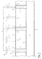
- this includes Embodiment of a manifold 1 Distribution housing 10, in which two chambers 2, 3 one above the other are formed.
- the pipe distributor 1 is for example in a heating system as a heating circuit distributor can be used, the upper chamber 2 then the flow chamber and the lower chamber 3 the return chamber forms.
- the two chambers 2, 3 are separated from each other by a horizontal one Partition 13 separated.
- the pipe distributor 1 In its installed state the pipe distributor 1 is aligned horizontally.
- the upper part of the distributor housing 10 can for example through a first C-profile 11 and the lower part a second C-profile 12 may be formed, the two C-profiles 11, 12 with their open sides facing each other are and wherein the partition 13 between the two C-profiles 11, 12 is arranged.
- the pipe distributor 1 comprises several pipe sections 4, at a predetermined distance, a double Corresponds to grid spacing A in the upper chamber 2 of the distributor housing 10 are arranged. Every piece of pipe 4 is flush with its upper end 41 with the top of an upper wall 11 'of the distributor housing 10 in an opening 14, the diameter corresponds to the outer diameter of the pipe section 4. For Sealing is appropriate between the top 41 of the pipe section 4 and the upper wall 11 'of the distributor housing 10 attached a weld or solder seam. With at its lower end each piece of pipe 4 projects through the Partition 13 through into the lower chamber 3 of the distributor housing 10. The passage of the pipe section 4 through the partition 13 is in each case by a welding or soldered seam sealed.
- the respective the inner diameter of the to be connected Pipeline 5 correspond.
- the first two seen from the left Pipelines 5 have an inside diameter that corresponds to the inside diameter corresponds to the pipe sections 4. That is why at the cover 40, which is in the pipe section 4 on the left in FIG. 1 a complete removal was done because the lid has exactly the diameter that the inner diameter he pipe 5 to be connected and thus also corresponds to the inner diameter of the pipe section 4.
- an opening 14 of the same diameter in the attached top wall 11 'of the distributor housing 10 wherein the position of the opening preferably by Marking made on the upper side of the upper wall 11 ' is specified to the required grid spacing A to ensure between the adjacent pipes 5.
- the attachment of the openings 14 can, for example by means of plasma cutting, whereby the Openings 14 are generated with such high accuracy that mechanical post-processing is no longer necessary is.
- the markings represent at least the Center of the opening 14 to be made; preferably include the markings to the center concentric circles representing the possible diameters to be generated for the connection of the pipelines 5 Breakthroughs in graded standard dimensions correspond.
- the third and fourth pipeline seen from the left in FIG. 1 5 have a slightly smaller diameter, so that after the opening 14 in the cover 40th of this a ring-shaped outer part on the upper End of the middle pipe section 4 in Figure 1 remains.
- the pipe 5 on the far right in FIG Reduced diameter again. This remains after attachment the correspondingly smaller opening 14 in Cover 40 of this is a slightly wider ring-shaped Remaining part at the upper end of the one on the far right in FIG Pipe section 4.
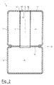
- FIG. 2 of the drawing shows the enlarged drawing Cross-section particularly clearly the C-shape of the two profiles 11, 12 with the intermediate Partition 13 form the distributor housing 10.
- the Pipe sections 4 which here at its upper end 41 with the cover 40 completely is closed, as is the delivery state of the Pipe distributor 1 corresponds.
- Figure 2 also illustrates the top of the top wall 11 'of the distributor housing 10 evenly, so that also a visually appealing and clean appearance is justified, especially in such cases, in which not all possible connections of the pipe distributor 1 can be used.
- markings 6 are attached at grid spacing A, which an aid for the installation of the openings 14 are.
- one of the markings 6 is on one the lid 40 is visible.
- the markings 6 include here both a the center of the opening to be made 14 representing central center mark as well as circles concentric to the center 60 the possible diameters for connecting the pipes 5 openings 14 to be generated in graded Correspond to standard dimensions. For durability and recognizability here are the markings 6, 60 executed in the form of recessed points and grooves.
- the distributor housing 10 On its foreheads, not shown in the drawing is the distributor housing 10 in the usual way closed by attached plates, preferably in this area, as usual, the other necessary connections, for example for a boiler flow and a boiler return are.
- the attachment the openings 14 in the lid 40 and in the upper Wall 11 'of the distributor housing 10 then takes place optionally according to customer specifications also in the manufacturing company or by the craftsman installing the pipe distributor 1 in advance in its operation or only at the installation site.
Landscapes
- Engineering & Computer Science (AREA)
- Physics & Mathematics (AREA)
- Thermal Sciences (AREA)
- Chemical & Material Sciences (AREA)
- Combustion & Propulsion (AREA)
- Mechanical Engineering (AREA)
- General Engineering & Computer Science (AREA)
- Branch Pipes, Bends, And The Like (AREA)
- Lining Or Joining Of Plastics Or The Like (AREA)
- Steam Or Hot-Water Central Heating Systems (AREA)
- Blow-Moulding Or Thermoforming Of Plastics Or The Like (AREA)
- Instantaneous Water Boilers, Portable Hot-Water Supply Apparatuses, And Control Of Portable Hot-Water Supply Apparatuses (AREA)
Applications Claiming Priority (2)
| Application Number | Priority Date | Filing Date | Title |
|---|---|---|---|
| DE20010701U DE20010701U1 (de) | 2000-06-15 | 2000-06-15 | Rohrverteiler, insbesondere für Heizungsanlagen |
| DE20010701U | 2000-06-15 |
Publications (3)
| Publication Number | Publication Date |
|---|---|
| EP1164334A2 true EP1164334A2 (fr) | 2001-12-19 |
| EP1164334A3 EP1164334A3 (fr) | 2003-04-16 |
| EP1164334B1 EP1164334B1 (fr) | 2004-11-24 |
Family
ID=7942917
Family Applications (1)
| Application Number | Title | Priority Date | Filing Date |
|---|---|---|---|
| EP01112525A Expired - Lifetime EP1164334B1 (fr) | 2000-06-15 | 2001-05-23 | Distributeur, en particulier pour installations de chauffage |
Country Status (3)
| Country | Link |
|---|---|
| EP (1) | EP1164334B1 (fr) |
| AT (1) | ATE283455T1 (fr) |
| DE (2) | DE20010701U1 (fr) |
Families Citing this family (2)
| Publication number | Priority date | Publication date | Assignee | Title |
|---|---|---|---|---|
| DE10325657B4 (de) | 2003-06-06 | 2005-07-21 | Eisenmann Maschinenbau Gmbh & Co. Kg | Heizmedium-Verteiler für eine mehrere Wärmetauscher umfassende Zuluftanlage |
| DE202005003778U1 (de) | 2005-03-09 | 2005-07-07 | Comfort Sinusverteiler Gmbh | Rohrverteiler, insbesondere für Heizungsanlagen |
Citations (2)
| Publication number | Priority date | Publication date | Assignee | Title |
|---|---|---|---|---|
| DE2116982A1 (de) | 1971-04-07 | 1972-10-19 | Grammer, Meinrad, 7241 Ergenzingen | Rohrleitungsverteileranlage für Vor- und Rücklaufleitungen, insbesondere für Warmwasser-Heizungsanlagen |
| DE3012854A1 (de) | 1980-04-02 | 1981-10-08 | Maile + Grammer Gmbh, 7407 Rottenburg | Rohrleitungsverteiler, insbesondere fuer warmwasserheuzungen |
Family Cites Families (4)
| Publication number | Priority date | Publication date | Assignee | Title |
|---|---|---|---|---|
| DE4105812A1 (de) * | 1991-02-23 | 1992-09-10 | Karl Lausser Gmbh | Gehaeuse fuer doppelkammer-verteiler |
| DE9218591U1 (de) * | 1992-09-10 | 1994-08-25 | Maatz, Alfons, 46395 Bocholt | Vorrichtung zum Aufteilen fließfähiger Stoffe auf Rohre |
| DE19512024C2 (de) * | 1995-03-31 | 1998-07-02 | Hans Straub | Verteilervorrichtung für Heizkessel u. dgl. |
| DE29702573U1 (de) * | 1997-02-14 | 1997-08-28 | Maatz, Alfons, 46395 Bocholt | Vorrichtung zum Verteilen und Sammeln von flüssigen Medien, insbesondere Vor- und Rücklaufverteiler von Heizwasser |
-
2000
- 2000-06-15 DE DE20010701U patent/DE20010701U1/de not_active Expired - Lifetime
-
2001
- 2001-05-23 DE DE50104580T patent/DE50104580D1/de not_active Expired - Lifetime
- 2001-05-23 EP EP01112525A patent/EP1164334B1/fr not_active Expired - Lifetime
- 2001-05-23 AT AT01112525T patent/ATE283455T1/de not_active IP Right Cessation
Patent Citations (2)
| Publication number | Priority date | Publication date | Assignee | Title |
|---|---|---|---|---|
| DE2116982A1 (de) | 1971-04-07 | 1972-10-19 | Grammer, Meinrad, 7241 Ergenzingen | Rohrleitungsverteileranlage für Vor- und Rücklaufleitungen, insbesondere für Warmwasser-Heizungsanlagen |
| DE3012854A1 (de) | 1980-04-02 | 1981-10-08 | Maile + Grammer Gmbh, 7407 Rottenburg | Rohrleitungsverteiler, insbesondere fuer warmwasserheuzungen |
Also Published As
| Publication number | Publication date |
|---|---|
| ATE283455T1 (de) | 2004-12-15 |
| EP1164334A3 (fr) | 2003-04-16 |
| DE20010701U1 (de) | 2001-10-31 |
| DE50104580D1 (de) | 2004-12-30 |
| EP1164334B1 (fr) | 2004-11-24 |
Similar Documents
| Publication | Publication Date | Title |
|---|---|---|
| DE102009052674B4 (de) | Verfahren und Vorrichtung zum Verbinden von Doppelmantelrohren | |
| DE4114307C2 (de) | Schwingungsdämpfer | |
| EP0715112A2 (fr) | Appareil pour connexion simultanée d'électrovannes | |
| EP0092032A2 (fr) | Dispositif pour transférer la chaleur d'un conduit de distribution à un consommateur | |
| DE3132602C2 (fr) | ||
| EP1038133A1 (fr) | Robinet sanitaire | |
| EP1164334B1 (fr) | Distributeur, en particulier pour installations de chauffage | |
| DE19512364C2 (de) | Anschlußanordnung für einen Röhrenheizkörper | |
| DE202005003778U1 (de) | Rohrverteiler, insbesondere für Heizungsanlagen | |
| WO2016198553A1 (fr) | Dispositif de montage pour un panneau de robinetterie | |
| DE102007063641B4 (de) | Verbindungsanordnung für den Installationsbereich | |
| DE10223790B4 (de) | Plattenheizkörper | |
| DE3627393C1 (en) | Connection part for joining a water meter to a T-shaped pipe connection | |
| DE10064976A1 (de) | Armatur mit Anschlussadapter | |
| DE9012553U1 (de) | Verteiler für strömende Medien, insbesondere Druckluft | |
| DE102021125713B4 (de) | Ölzuführanordnung für eine Brennkraftmaschine und Brennkraftmaschine mit einer solchen Ölzuführanordnung | |
| DE29920410U1 (de) | Klappe mit Rohradapter | |
| DE29808031U1 (de) | Paneel- bzw. Flachheizkörper | |
| AT405208B (de) | T-förmiger rohrteil | |
| DE3026590A1 (de) | Kombinierte vorlaufverteiler und ruecklaufsammler, insbes. fuer warmwasser- fussbodenheizungen | |
| DE20302761U1 (de) | Blindstopfen und Verbindungsanordnung | |
| DE2733892B2 (de) | Rohrverbindung zwischen sich kreuzenden Rohren eines Register-Heizkörpers aus Aluminium | |
| DE29804738U1 (de) | Heizkörper | |
| DE29501595U1 (de) | Verteiler für Fluide | |
| DE20104459U1 (de) | Anschlussgarnitur für einen Plattenheizkörper |
Legal Events
| Date | Code | Title | Description |
|---|---|---|---|
| PUAI | Public reference made under article 153(3) epc to a published international application that has entered the european phase |
Free format text: ORIGINAL CODE: 0009012 |
|
| AK | Designated contracting states |
Kind code of ref document: A2 Designated state(s): AT BE CH CY DE DK ES FI FR GB GR IE IT LI LU MC NL PT SE TR |
|
| AX | Request for extension of the european patent |
Free format text: AL;LT;LV;MK;RO;SI |
|
| PUAL | Search report despatched |
Free format text: ORIGINAL CODE: 0009013 |
|
| AK | Designated contracting states |
Designated state(s): AT BE CH CY DE DK ES FI FR GB GR IE IT LI LU MC NL PT SE TR |
|
| AX | Request for extension of the european patent |
Extension state: AL LT LV MK RO SI |
|
| 17P | Request for examination filed |
Effective date: 20030904 |
|
| AKX | Designation fees paid |
Designated state(s): AT CH DE FR LI NL |
|
| GRAP | Despatch of communication of intention to grant a patent |
Free format text: ORIGINAL CODE: EPIDOSNIGR1 |
|
| GRAS | Grant fee paid |
Free format text: ORIGINAL CODE: EPIDOSNIGR3 |
|
| GRAA | (expected) grant |
Free format text: ORIGINAL CODE: 0009210 |
|
| AK | Designated contracting states |
Kind code of ref document: B1 Designated state(s): AT CH DE FR LI NL |
|
| REG | Reference to a national code |
Ref country code: CH Ref legal event code: EP |
|
| REF | Corresponds to: |
Ref document number: 50104580 Country of ref document: DE Date of ref document: 20041230 Kind code of ref document: P |
|
| REG | Reference to a national code |
Ref country code: IE Ref legal event code: FG4D Free format text: GERMAN |
|
| REG | Reference to a national code |
Ref country code: CH Ref legal event code: NV Representative=s name: PATMED AG |
|
| REG | Reference to a national code |
Ref country code: IE Ref legal event code: FD4D |
|
| PLBE | No opposition filed within time limit |
Free format text: ORIGINAL CODE: 0009261 |
|
| STAA | Information on the status of an ep patent application or granted ep patent |
Free format text: STATUS: NO OPPOSITION FILED WITHIN TIME LIMIT |
|
| ET | Fr: translation filed | ||
| 26N | No opposition filed |
Effective date: 20050825 |
|
| PGFP | Annual fee paid to national office [announced via postgrant information from national office to epo] |
Ref country code: NL Payment date: 20090504 Year of fee payment: 9 |
|
| PGFP | Annual fee paid to national office [announced via postgrant information from national office to epo] |
Ref country code: AT Payment date: 20090514 Year of fee payment: 9 Ref country code: FR Payment date: 20090515 Year of fee payment: 9 |
|
| PGFP | Annual fee paid to national office [announced via postgrant information from national office to epo] |
Ref country code: CH Payment date: 20090513 Year of fee payment: 9 |
|
| REG | Reference to a national code |
Ref country code: NL Ref legal event code: V1 Effective date: 20101201 |
|
| REG | Reference to a national code |
Ref country code: CH Ref legal event code: PL |
|
| PG25 | Lapsed in a contracting state [announced via postgrant information from national office to epo] |
Ref country code: AT Free format text: LAPSE BECAUSE OF NON-PAYMENT OF DUE FEES Effective date: 20100523 |
|
| REG | Reference to a national code |
Ref country code: FR Ref legal event code: ST Effective date: 20110131 |
|
| PG25 | Lapsed in a contracting state [announced via postgrant information from national office to epo] |
Ref country code: CH Free format text: LAPSE BECAUSE OF NON-PAYMENT OF DUE FEES Effective date: 20100531 Ref country code: LI Free format text: LAPSE BECAUSE OF NON-PAYMENT OF DUE FEES Effective date: 20100531 |
|
| PG25 | Lapsed in a contracting state [announced via postgrant information from national office to epo] |
Ref country code: NL Free format text: LAPSE BECAUSE OF NON-PAYMENT OF DUE FEES Effective date: 20101201 |
|
| PG25 | Lapsed in a contracting state [announced via postgrant information from national office to epo] |
Ref country code: FR Free format text: LAPSE BECAUSE OF NON-PAYMENT OF DUE FEES Effective date: 20100531 |
|
| PGFP | Annual fee paid to national office [announced via postgrant information from national office to epo] |
Ref country code: DE Payment date: 20120719 Year of fee payment: 12 |
|
| PG25 | Lapsed in a contracting state [announced via postgrant information from national office to epo] |
Ref country code: DE Free format text: LAPSE BECAUSE OF NON-PAYMENT OF DUE FEES Effective date: 20131203 |
|
| REG | Reference to a national code |
Ref country code: DE Ref legal event code: R119 Ref document number: 50104580 Country of ref document: DE Effective date: 20131203 |