EP1164362B1 - Dosieransatz zum Ausbringen einer veränderbaren Dosis und ein Behälter mit einem solchen Dosieransatz - Google Patents
Dosieransatz zum Ausbringen einer veränderbaren Dosis und ein Behälter mit einem solchen Dosieransatz Download PDFInfo
- Publication number
- EP1164362B1 EP1164362B1 EP01401081A EP01401081A EP1164362B1 EP 1164362 B1 EP1164362 B1 EP 1164362B1 EP 01401081 A EP01401081 A EP 01401081A EP 01401081 A EP01401081 A EP 01401081A EP 1164362 B1 EP1164362 B1 EP 1164362B1
- Authority
- EP
- European Patent Office
- Prior art keywords
- piston
- product
- chamber
- container
- dosing nozzle
- Prior art date
- Legal status (The legal status is an assumption and is not a legal conclusion. Google has not performed a legal analysis and makes no representation as to the accuracy of the status listed.)
- Expired - Lifetime
Links
Images


Classifications
-
- G—PHYSICS
- G01—MEASURING; TESTING
- G01F—MEASURING VOLUME, VOLUME FLOW, MASS FLOW OR LIQUID LEVEL; METERING BY VOLUME
- G01F11/00—Apparatus requiring external operation adapted at each repeated and identical operation to measure and separate a predetermined volume of fluid or fluent solid material from a supply or container, without regard to weight, and to deliver it
- G01F11/10—Apparatus requiring external operation adapted at each repeated and identical operation to measure and separate a predetermined volume of fluid or fluent solid material from a supply or container, without regard to weight, and to deliver it with measuring chambers moved during operation
- G01F11/12—Apparatus requiring external operation adapted at each repeated and identical operation to measure and separate a predetermined volume of fluid or fluent solid material from a supply or container, without regard to weight, and to deliver it with measuring chambers moved during operation of the valve type, i.e. the separating being effected by fluid-tight or powder-tight movements
- G01F11/14—Apparatus requiring external operation adapted at each repeated and identical operation to measure and separate a predetermined volume of fluid or fluent solid material from a supply or container, without regard to weight, and to deliver it with measuring chambers moved during operation of the valve type, i.e. the separating being effected by fluid-tight or powder-tight movements wherein the measuring chamber reciprocates
- G01F11/16—Apparatus requiring external operation adapted at each repeated and identical operation to measure and separate a predetermined volume of fluid or fluent solid material from a supply or container, without regard to weight, and to deliver it with measuring chambers moved during operation of the valve type, i.e. the separating being effected by fluid-tight or powder-tight movements wherein the measuring chamber reciprocates for liquid or semiliquid
-
- G—PHYSICS
- G01—MEASURING; TESTING
- G01F—MEASURING VOLUME, VOLUME FLOW, MASS FLOW OR LIQUID LEVEL; METERING BY VOLUME
- G01F11/00—Apparatus requiring external operation adapted at each repeated and identical operation to measure and separate a predetermined volume of fluid or fluent solid material from a supply or container, without regard to weight, and to deliver it
- G01F11/02—Apparatus requiring external operation adapted at each repeated and identical operation to measure and separate a predetermined volume of fluid or fluent solid material from a supply or container, without regard to weight, and to deliver it with measuring chambers which expand or contract during measurement
- G01F11/04—Apparatus requiring external operation adapted at each repeated and identical operation to measure and separate a predetermined volume of fluid or fluent solid material from a supply or container, without regard to weight, and to deliver it with measuring chambers which expand or contract during measurement of the free-piston type
-
- G—PHYSICS
- G01—MEASURING; TESTING
- G01F—MEASURING VOLUME, VOLUME FLOW, MASS FLOW OR LIQUID LEVEL; METERING BY VOLUME
- G01F11/00—Apparatus requiring external operation adapted at each repeated and identical operation to measure and separate a predetermined volume of fluid or fluent solid material from a supply or container, without regard to weight, and to deliver it
- G01F11/02—Apparatus requiring external operation adapted at each repeated and identical operation to measure and separate a predetermined volume of fluid or fluent solid material from a supply or container, without regard to weight, and to deliver it with measuring chambers which expand or contract during measurement
- G01F11/08—Apparatus requiring external operation adapted at each repeated and identical operation to measure and separate a predetermined volume of fluid or fluent solid material from a supply or container, without regard to weight, and to deliver it with measuring chambers which expand or contract during measurement of the diaphragm or bellows type
- G01F11/082—Apparatus requiring external operation adapted at each repeated and identical operation to measure and separate a predetermined volume of fluid or fluent solid material from a supply or container, without regard to weight, and to deliver it with measuring chambers which expand or contract during measurement of the diaphragm or bellows type of the squeeze container type
Definitions
- the present invention relates to a metering tip for dispensing, either in metered form or in unmeasured form, a fluid product, especially a cosmetic product such as a shampoo, a conditioner, a gel, a lotion, milk, etc.
- a fluid product especially a cosmetic product such as a shampoo, a conditioner, a gel, a lotion, milk, etc.
- the invention also relates to a packaging and dispensing assembly equipped with a metering nozzle according to the present invention, the distribution of the product by means of such an assembly being operated in the head down position of the latter.
- the US-A-5,090,600 describes a metering tip of the type comprising a metering chamber formed inside a piston, a free end of which is provided with openings able to allow the metered outlet of the product.
- the opening of the openings of the metering chamber is obtained by means of a pressure exerted by the product on one face of the piston.
- the product then flows through gravity in the open position of the openings.
- the closure element emerges sensibly out of the metering chamber.
- Such a tip is particularly suitable for the metered dispensing of highly liquid products such as drinks.
- such a system can hardly be used for the distribution of viscous products, such as commonly used in particular in the field of cosmetics. Indeed, the viscosity of these products, does not allow a fast enough flow of the dose of product, under the sole effect of its weight.
- the US-A-2,904,227 discloses a nozzle for the metered dispensing of a product, comprising a metering chamber inside which is slidably mounted a piston.
- the piston is traversed by an axial channel terminating in the vicinity of the free end of the piston by a radial portion opening on an outlet orifice. In the rest position, the outlet orifice is closed. To dispense a dose of product, the outlet orifice is released under the pressure of the product exerted on the piston.
- the product flows through a radial portion of the channel, passes into the axial portion of the channel, and exits through the radial outlet.
- the continuous component corresponds to the amount of product passing from the container to the variable volume chamber before the piston reaches the second position. Indeed, at least when the piston moves from the first to the second position, and vice versa when it returns from the second to the first position, the variable volume chamber is in communication with the container.
- the "conditions for the exercise of pressure” are mainly concerned with the value of the pressure exerted and the duration during which this pressure is exerted.
- a high value pressure applied for a short time will cause the distribution of a substantially fixed component dose.
- a high pressure, applied suddenly will cause the rapid passage of the piston in the position where the outlet orifice is closed, thereby limiting the volume of product that can flow continuously from the container to the variable volume chamber.
- the product is pressurized inside the container by producing the latter in the form of a container with deformable walls.
- Such walls in response to pressure exerted perpendicularly to their surface, deform elastically to reduce the volume of the container, and to correspondingly pressurize the product within the container. When the pressure on the walls ceases, they return to their original shape.
- variable volume chamber forms a buffer that fills substantially completely each time the piston returns from the second position to the first, and whatever the level of product remaining in the container.
- the pressurization of the product can be done by means of a piston slidably mounted within a cylindrical container, or any other equivalent means.
- the degree of closure of the outlet orifice (s), when the piston occupies said first and second positions, depends to a large extent on the viscosity of the product, the essential point being that when the container equipped with a tip according to the invention is turned upside down, the product does not flow under the effect of its weight via the (or) orifice (s) output.
- the viscosity of the product ensuring in a way "self-sealing" of the outlet.
- specific means will be provided for this purpose.
- the means ensuring the closing of the outlet orifice when the piston is in the first position may be identical or distinct from the means ensuring the closure of the outlet orifice when the piston is in the second position.
- the closure of the outlet orifice may be provided by any means arranged in the outlet orifice, or in the vicinity of the latter, so as to seal it, or by any means capable of isolating the outlet orifice of the product contained in the container.
- the piston is traversed by, and / or delimits, at least one passage ensuring a permanent communication between the container and the variable volume chamber.
- These passages when the piston passes from the first position to the second, allow the passage of a volume of product in the variable volume chamber, corresponding to the continuous component of the dose.
- these passages and / or orifices allow the immediate filling of the variable volume chamber.
- At least one peripheral passage is delimited by a peripheral edge of the piston, in combination with an internal surface of the body of said chamber.
- three peripheral passages are arranged regularly opposite the peripheral edge of the piston, and separated by three corresponding guide portions of the piston.
- the piston may comprise at least one passage passing through the piston and opening on a first face disposed facing the container, and on a second face, opposite to the first, arranged facing the variable volume chamber.
- the piston comprises a plurality of passages passing through the piston, and regularly spaced on the surface thereof.
- three orifices with a diameter of between 2 mm and 2.5 mm are regularly spaced, in the vicinity of the peripheral edge of the piston.
- the piston is configured so that, when in the second position, it isolates the outlet orifice of the variable volume chamber.
- the piston can, on the side facing towards the outlet orifice, form a groove into which the free edge of an axial skirt formed around the outlet orifice engages, and with which the piston comes into engagement when in the second position.
- return means in particular in the form of a helical spring, are provided for, when the product pressure ceases on the piston, the latter is resiliently returned to the first position.
- a helical spring when the turns which form it are contiguous (in the second position of the piston) can serve as closure member of the outlet orifice of the variable volume chamber.
- the outlet orifice of the variable volume chamber is formed in an end wall of the body of the measuring nozzle, arranged opposite the piston, and at a distance from the latter when the piston is in the second position. .
- an elastically deformable membrane is disposed in the outlet orifice, said membrane comprising at least one slot, closed in the absence of pressure inside the measuring tip, and suitable to open in response to pressure exerted by the product contained in the variable volume chamber.
- the membrane improves closure of the outlet port when the piston is in the first position.
- the membrane can be glued, slammed, or welded around the outlet. Such a membrane also makes it possible to maintain the outlet orifice in a state of satisfactory cleanliness, and makes it possible to interrupt the flow of product instantaneously.
- the degree of closure of the slit depends to a large extent on the viscosity of the product.
- the edges which delimit the slot may be more or less contiguous, the essential being that they are close enough to retain the product inside the measuring tip when a container equipped with such a measuring tip, is returned upside down.
- said membrane is adapted, in response to a pressure exerted by the product contained in the variable volume chamber, to occupy a convex profile turned towards the outside of the metering nozzle, and, by a suction phenomenon when the walls return to their original shape, and when the piston returns from the second position to the first, to turn to occupy a convex profile turned towards the interior of the container.
- a pressure exerted by the product contained in the variable volume chamber to occupy a convex profile turned towards the outside of the metering nozzle, and, by a suction phenomenon when the walls return to their original shape, and when the piston returns from the second position to the first, to turn to occupy a convex profile turned towards the interior of the container.
- Such a membrane may be made of a material chosen from thermoplastic or crosslinked elastomers, in particular silicones, natural or synthetic latices, EPDMs, polyurethanes, polypropylene and SBS, SEBS, or EPDM blends, polyethylenes and polyesters. very low density, mixtures based on polyesters glycols (TPU) or polyether glycols (PEBA and COPE), flexible polyvinyl chlorides (PVC).
- thermoplastic or crosslinked elastomers in particular silicones, natural or synthetic latices, EPDMs, polyurethanes, polypropylene and SBS, SEBS, or EPDM blends, polyethylenes and polyesters.
- thermoplastic or crosslinked elastomers in particular silicones, natural or synthetic latices, EPDMs, polyurethanes, polypropylene and SBS, SEBS, or EPDM blends, polyethylenes and polyesters.
- TPU polyesters glycols
- PEBA and COPE polyether glycols
- an assembly is also produced for the packaging and the metered distribution of a product (P), in particular a cosmetic product, comprising a container formed of a body whose one end is closed by a bottom, another end forming a neck whose free edge defines an opening, a measuring tip according to the invention being fixedly mounted on said neck.
- a product in particular a cosmetic product
- the container may be in the form of a tube, or a bottle. Its section may be any, in particular oval, elliptical or circular.
- a cap may be provided for, in particular in the storage position, removably cover said measuring tip.
- the measuring tip is mounted in the axis of the container. However, this is not a necessary feature. In some cases it may be desirable to mount the metering tip at an angle to the axis of the container to improve the emptying rate of the container.
- the container body may have crushable walls when a pressure (F) is exerted on the container, substantially perpendicular to said walls, and return to their original shape when said pressure ceases.
- Other means however, including a piston, could be considered to pressurize the product to force the output through the metering tip.
- Such an assembly is particularly suitable for the packaging and the metered distribution of a cosmetic product, in particular a shampoo, a conditioner, a styling gel, a milk, or a care cream.
- a cosmetic product in particular a shampoo, a conditioner, a styling gel, a milk, or a care cream.
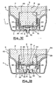
- the tip 1 represented at figure 2 comprises a dressing skirt 50 and a hanging skirt 2 whose inner surface comprises a bead 3 adapted to cooperate by snapping with a corresponding bead 4 formed on the outer surface of the neck 5 of a container 6 (shown in position upside down), especially a bottle with deformable walls.
- a dressing skirt 50 and a hanging skirt 2 whose inner surface comprises a bead 3 adapted to cooperate by snapping with a corresponding bead 4 formed on the outer surface of the neck 5 of a container 6 (shown in position upside down), especially a bottle with deformable walls.
- other means could be used to ensure the mounting of the tip 1 on the container 6 (screwing, gluing, welding, etc.)
- the measuring nozzle 1 further comprises a skirt 9 of concentric X axis with the side skirt 2, of diameter slightly less than the inside diameter of the neck 5 so as to fit tightly inside said neck.
- a sealing lip (not shown) can complete the sealing of the mounting of the measuring tip 1 on the container 6.
- the variable volume chamber 20 which will now be described in detail comprises a cylindrical body constituted by the skirt 9, inside which a piston 21 is slidably guided.
- the peripheral edge 24 of the piston 21 has a a plurality of ribs 22, 23 spaced regularly, and delimiting in combination with the peripheral edge 24 of the piston 21 and with the inner surface of the skirt 9, a plurality of peripheral passages 25, 26 whose function will be explained in more detail later. .
- the ribs 22 and 23 guide the piston 21 during its sliding movement in the cylindrical body 9.
- the piston comprises three ribs defining three peripheral passages whose radial width is of the order of 1 mm.
- the piston is traversed by a plurality of orifices 27, 28 opening on the one hand inside the variable volume chamber 20, and on the other side, towards the container 6.
- three holes are made regularly spaced in the vicinity of the periphery of the piston, and whose diameter is about 2.2 mm.
- An elastomeric membrane 32 is disposed in the dispensing orifice 8. Such a membrane may be glued, slammed or welded all around the dispensing orifice 8.
- the membrane 32 comprises at least one slot 33, closed in the absence pressure inside the metering tip, and able to open in response to a pressure exerted by the product contained within the variable volume chamber 20.
- the membrane 32 is configured so that, in the manner of a "teat", in response to a pressure exerted by the product contained in the variable volume chamber 20, it has a convex profile facing outwardly of the measuring tip (see figure 3B ).
- a suction phenomenon when the piston 21 returns to the high position, and when the walls resume their undistorted position, the membrane 32 turns to occupy a convex profile facing towards the inside of the container, as shown in FIG. figure 2 , or Figures 3A and 3D .
- the piston 21 is movable axially between: a) a high position in which it bears against the bead 29. In this position the outlet orifice 8 of the variable volume chamber is sealed to the product by the pacifier 32; and b) a low position in which the groove 31 of the piston 21 is in engagement with the free edge of the skirt 30, thus isolating the dispensing orifice 8 of the variable volume chamber 20.
- the assembly 100 on which is mounted metering nozzle 1 according to the invention consists of a bottle 6, for example, polyethylene or polypropylene.
- the bottle 6 comprises a body 61 closed by a bottom 62.
- the body is of elongate cross section and is formed of two large faces 63, 64, deformable "elastically" under the effect of a pressure F exerted, as illustrated to the Figure 1B , perpendicular to the long sides of the bottle.
- FIGS. 1A-1B , and 3A-3D which are now referred to, illustrate the operation of the dosing nozzle described with reference to the figure 2 .
- the container 6 In the rest position (as described with reference to the figure 3A ), the container 6 is preferably placed upside down on a flat surface. In this position, the outlet orifice 8 of the variable volume chamber 20 is closed by the nipple 32. The piston 21, biased by the spring 34 is in abutment against the bead 29 formed by the skirt 9.
- the peripheral passages 25 , 26, as well as the orifices 27, 28 ensure the permanent communication between the container 6 and the variable volume chamber 20, which has been filled almost completely during the return to the high position of the piston 21, during the last use of the device.
- This rest position also corresponds to that represented in Figure 1A .
- the amount of product dispensed depends on how the user pressurizes the walls of the container. However, under identical pressurization conditions (specific to each user), the quantity of product dispensed is substantially the same, at plus or minus about 20%. On the other hand, by modifying the conditions for exerting pressure on the walls of the receptacle, in particular by pressing more gently over a longer period (as opposed to a brief and strong support), the dose dispensed will be greater because of the a larger amount of product that has passed continuously from the container 6 to the chamber 20 before the piston 21 bears on the skirt 30.
- variable volume chamber is substantially full.
- the depression prevailing inside the container, as well as inside the variable volume chamber 20 causes the tilting of the "teat” 32 towards the inside of the measuring tip 1 and an air inlet via the slot or slots 33 which pass through it.
- the air also enters the container, which compensates inside the latter, the volume of product distributed. The device is thus ready for a new use.
Landscapes
- Physics & Mathematics (AREA)
- Fluid Mechanics (AREA)
- General Physics & Mathematics (AREA)
- Containers And Packaging Bodies Having A Special Means To Remove Contents (AREA)
- Closures For Containers (AREA)
- Infusion, Injection, And Reservoir Apparatuses (AREA)
Claims (14)
- Dosieraufsatz (1) zur Bestückung eines ein Produkt (P) enthaltenden Behälters (6), wobei der Aufsatz eine Kammer mit variablem Volumen (20) aufweist, die mit einem Kolben (21) ausgestattet ist, der gleitend innerhalb des Körpers (9) der Kammer geführt wird, wobei der Kolben (21) als Reaktion auf einen vom Produkt ausgeübten Druck fähig ist, sich zwischen einer ersten Stellung, in der die Kammer (20) ein maximales Volumen hat, und einer zweiten Stellung zu verschieben, in der die Kammer (20) ein minimales Volumen hat, wobei die Verschiebung die Ausgabe eines Produktvolumens (P) durch mindestens eine Austrittsöffnung (8) bewirkt, die verschlossen ist, wenn der Kolben (21) in der ersten und der zweiten Stellung ist, wobei die Kammer (20) so mit dem Behälter (6) in Verbindung stehen kann, dass das als Reaktion auf die Verschiebung ausgegebene Produktvolumen eine feste Komponente, die der Differenz zwischen dem maximalen und dem minimalen Volumen entspricht, und eine kontinuierliche Komponente aufweist, die mit den Bedingungen der Ausübung des Drucks des Produkts (P) auf den Kolben (21) verbunden ist, dadurch gekennzeichnet, dass der Kolben (21) von mindestens einem Durchgang (25-28) durchquert wird und/oder ihn begrenzt, der eine permanente Verbindung zwischen dem Behälter (6) und der Kammer mit variablem Volumen (20) gewährleistet.
- Dosieraufsatz (1) nach Anspruch 1, dadurch gekennzeichnet, dass mindestens ein Umfangsdurchgang (25, 26) von einem Umfangsrand des Kolbens (21) in Kombination mit einer Innenfläche des Körpers (9) der Kammer (20) begrenzt wird.
- Dosieraufsatz (1) nach Anspruch 2, dadurch gekennzeichnet, dass er mehrere Umfangsdurchgänge (25, 26) aufweist, die durch mehrere Abschnitte (22, 23) getrennt sind, die die Führung der gleitenden Bewegung des Kolbens (21) im Körper (9) der Kammer mit variablem Volumen (20) gewährleisten.
- Dosieraufsatz (1) nach einem der Ansprüche 1 bis 3, dadurch gekennzeichnet, dass mindestens ein Durchgang (27, 28) den Kolben (71) durchquert und an einer ersten Seite, die gegenüber dem Behälter (6) angeordnet ist, und an einer zweiten, der ersten gegenüberliegenden Seite mündet, die gegenüber der Kammer mit variablem Volumen (20) angeordnet ist.
- Dosieraufsatz (1) nach Anspruch 4, dadurch gekennzeichnet, dass er mehrere Durchgänge (27, 28) aufweist, die den Kolben (21) durchqueren und auf dessen Fläche einen gleichmäßigen Abstand haben.
- Dosieraufsatz (1) nach einem der vorhergehenden Ansprüche, dadurch gekennzeichnet, dass der Kolben (21) so konfiguriert ist, dass er, wenn er in der zweiten Stellung ist, die Austrittsöffnung (8) von der Kammer mit variablem Volumen (20) isoliert.
- Dosieraufsatz (1) nach einem der vorhergehenden Ansprüche, dadurch gekennzeichnet, dass Rückstellmittel (34), insbesondere in Form einer Spiralfeder, vorgesehen sind, damit, wenn der Druck des Produkts (P) auf den Kolben (71) endet, letzterer elastisch in die erste Stellung zurückgestellt wird.
- Dosieraufsatz (1) nach einem der Ansprüche 1 bis 7, dadurch gekennzeichnet, dass die Austrittsöffnung (8) der Kammer mit variablem Volumen (20) eine Endwand (7) des Körpers (9) des Dosieraufsatzes durchquert, die gegenüber dem Kolben (21) und in Abstand zu diesem angeordnet ist, wenn der Kolben (21) in der zweiten Stellung ist.
- Dosieraufsatz (1) nach Anspruch 8, dadurch gekennzeichnet, dass eine elastisch verformbare Membran (32) in der Austrittsöffnung (8) angeordnet ist, wobei die Membran (32) mindestens einen Schlitz (33) aufweist, der in Abwesenheit eines ausreichenden Drucks innerhalb des Dosieraufsatzes (1) geschlossen ist, und der sich als Reaktion auf einen von dem im Inneren der Kammer mit variablem Volumen (20) enthaltenen Produkt (P) ausgeübten Druck öffnen kann.
- Dosieraufsatz (1) nach Anspruch 9, dadurch gekennzeichnet, dass die Membran (32) als Reaktion auf einen von dem in der Kammer mit variablem Volumen (20) enthaltenen Produkt (P) ausgeübten Druck fähig ist, ein konvexes Profil anzunehmen, das nach außerhalb des Dosieraufsatzes (1) gerichtet ist, und ein nach innerhalb der Kammer (20) gerichtetes konvexes Profil anzunehmen, wenn der Kolben von der zweiten in die erste Stellung zurückkehrt.
- Dosieraufsatz (1) nach Anspruch 9 oder 10, dadurch gekennzeichnet, dass die Membran (32) aus einem Material hergestellt wird, das aus den thermoplastischen oder vernetzten Elastomermaterialien ausgewählt wird, insbesondere den Siliconen, den natürlichen oder synthetischen Latexmaterialien, den EPDM, den Polyurethanen, den Mischungen aus Polypropylen und SBS, SEBS, oder EPDM, den Polyethylenen sehr niedriger Dichte, den Mischungen auf der Basis von Polyesterglycolen (TPU) oder von Polyetherglycolen (PESA und COPE), den weichen Polyvinylchloriden (PVC).
- Einheit (100) zur Verpackung und zur dosierten Ausgabe eines Produkts (P), insbesondere eines kosmetischen Produkts, die einen Behälter (6) aufweist, der von einem Körper (61) gebildet wird, von dem ein Ende von einem Boden (62) verschlossen wird, während das andere Ende einen Hals (5) bildet, von dem ein freier Rand eine Öffnung begrenzt, wobei ein Dosieraufsatz (1) fest auf den Hals montiert ist, dadurch gekennzeichnet, dass der Dosieraufsatz (1) einem der vorhergehenden Ansprüche entspricht.
- Einheit (100) nach Anspruch 12, dadurch gekennzeichnet, dass der Körper (61) Wände (63, 64) aufweist, die zusammengedrückt werden können, wenn ein Druck (F) auf den Behälter (6) lotrecht zu den Wänden ausgeübt wird, und in ihre Ursprungsform zurückkommen können, wenn der Druck endet.
- Verwendung einer Einheit (100) nach einem der Ansprüche 12 oder 13 zur Verpackung und zur dosierten Ausgabe eines kosmetischen Produkts, insbesondere eines Shampoos, einer Spülung, eines Frisiergels, einer Milch oder einer Pflegecreme.
Applications Claiming Priority (2)
| Application Number | Priority Date | Filing Date | Title |
|---|---|---|---|
| FR0006927A FR2809712B1 (fr) | 2000-05-30 | 2000-05-30 | Embout doseur pour la distribution d'une dose a volume variable et ensemble equipe d'un tel embout doseur |
| FR0006927 | 2000-05-30 |
Publications (2)
| Publication Number | Publication Date |
|---|---|
| EP1164362A1 EP1164362A1 (de) | 2001-12-19 |
| EP1164362B1 true EP1164362B1 (de) | 2008-12-17 |
Family
ID=8850788
Family Applications (1)
| Application Number | Title | Priority Date | Filing Date |
|---|---|---|---|
| EP01401081A Expired - Lifetime EP1164362B1 (de) | 2000-05-30 | 2001-04-26 | Dosieransatz zum Ausbringen einer veränderbaren Dosis und ein Behälter mit einem solchen Dosieransatz |
Country Status (8)
| Country | Link |
|---|---|
| US (1) | US6415961B2 (de) |
| EP (1) | EP1164362B1 (de) |
| JP (1) | JP2002053161A (de) |
| AT (1) | ATE418066T1 (de) |
| CA (1) | CA2349781C (de) |
| DE (1) | DE60136993D1 (de) |
| ES (1) | ES2319730T3 (de) |
| FR (1) | FR2809712B1 (de) |
Cited By (2)
| Publication number | Priority date | Publication date | Assignee | Title |
|---|---|---|---|---|
| RU2682124C2 (ru) * | 2014-03-31 | 2019-03-14 | Капартис Аг | Дозирующее устройство для подачи жидкости |
| RU2737137C2 (ru) * | 2016-07-14 | 2020-11-25 | Ф. Хольцер Гмбх | Дозатор и дозирующее устройство |
Families Citing this family (60)
| Publication number | Priority date | Publication date | Assignee | Title |
|---|---|---|---|---|
| FR2809088B1 (fr) * | 2000-05-19 | 2002-07-26 | Oreal | Embout doseur et ensemble de distribution equipe d'un tel embout |
| EP1425557A1 (de) * | 2001-09-12 | 2004-06-09 | Anthony Charles Lammond Wass | Verbesserte dosiervorrichtung |
| US6726063B2 (en) * | 2002-04-04 | 2004-04-27 | Stull Technologies | Self-cleaning shape memory retaining valve |
| US7767152B2 (en) | 2003-08-11 | 2010-08-03 | Sakura Finetek U.S.A., Inc. | Reagent container and slide reaction retaining tray, and method of operation |
| US9518899B2 (en) | 2003-08-11 | 2016-12-13 | Sakura Finetek U.S.A., Inc. | Automated reagent dispensing system and method of operation |
| US7744817B2 (en) | 2003-08-11 | 2010-06-29 | Sakura Finetek U.S.A., Inc. | Manifold assembly |
| US7501283B2 (en) * | 2003-08-11 | 2009-03-10 | Sakura Finetek U.S.A., Inc. | Fluid dispensing apparatus |
| US20050173457A1 (en) * | 2004-02-09 | 2005-08-11 | Berard Paul W. | Ready serve distribution bottle |
| EP1602298B1 (de) * | 2004-06-04 | 2012-10-03 | Schwan-STABILO Cosmetics GmbH & Co. KG | Auftraggerät |
| US20060186135A1 (en) * | 2005-02-22 | 2006-08-24 | Rose Gary D | Novelty dispensers and methods thereof |
| DE502006001674D1 (de) * | 2006-01-18 | 2008-11-13 | Geka Brush Gmbh | Kosmetikeinheit |
| DE102006017957B3 (de) * | 2006-04-13 | 2007-05-16 | Kunststofftechnik Waidhofen An | Selbstschließendes Ventil |
| DE102006021564B3 (de) * | 2006-05-08 | 2007-03-29 | Ccc Udo Suffa Gmbh | Selbstschließendes Ventil mit Ventildeckel |
| US8459509B2 (en) | 2006-05-25 | 2013-06-11 | Sakura Finetek U.S.A., Inc. | Fluid dispensing apparatus |
| US20080110938A1 (en) * | 2006-11-13 | 2008-05-15 | Fun-Damental Too, Ltd. | Forcibly sealed duckbill valve |
| JP5008958B2 (ja) * | 2006-11-30 | 2012-08-22 | 株式会社吉野工業所 | 押出容器 |
| US7959036B2 (en) * | 2007-02-01 | 2011-06-14 | Paul Koh | Elastomeric dispensing container |
| US20080203116A1 (en) * | 2007-02-28 | 2008-08-28 | Lagace Chad E | Metering dispenser |
| GB0719827D0 (en) * | 2007-10-11 | 2007-11-21 | Unilever Plc | Refill bottle for appliance dispensing heated cosmetic fluids |
| WO2009093798A1 (en) * | 2008-01-25 | 2009-07-30 | Lee Hwa Chang Co., Ltd | Container and scalp massager with the container |
| US8986253B2 (en) | 2008-01-25 | 2015-03-24 | Tandem Diabetes Care, Inc. | Two chamber pumps and related methods |
| US8408421B2 (en) | 2008-09-16 | 2013-04-02 | Tandem Diabetes Care, Inc. | Flow regulating stopcocks and related methods |
| AU2009293019A1 (en) | 2008-09-19 | 2010-03-25 | Tandem Diabetes Care Inc. | Solute concentration measurement device and related methods |
| AU2010217760B2 (en) | 2009-02-27 | 2015-04-09 | Tandem Diabetes Care, Inc. | Methods and devices for determination of flow reservoir volume |
| US9250106B2 (en) | 2009-02-27 | 2016-02-02 | Tandem Diabetes Care, Inc. | Methods and devices for determination of flow reservoir volume |
| EP3284494A1 (de) | 2009-07-30 | 2018-02-21 | Tandem Diabetes Care, Inc. | Tragbares infusionspumpensystem |
| MX2012002935A (es) * | 2009-09-11 | 2012-06-01 | Kraft Foods Global Brands Llc | Recipientes y metodos para dispensar dosis multiples de un liquido concentrado, y liquidos concentrados estables en estante. |
| BR112012005984A2 (pt) * | 2009-09-18 | 2016-03-15 | Procter & Gamble | aparelho para dispensar dose unitária |
| WO2011106539A1 (en) * | 2010-02-24 | 2011-09-01 | Colgate-Palmolive Company | Dispenser cap with selectable reservoirs |
| WO2012062576A1 (en) * | 2010-11-09 | 2012-05-18 | Unilever Nv | Dosing cap for container |
| US8752732B2 (en) | 2011-02-01 | 2014-06-17 | Sakura Finetek U.S.A., Inc. | Fluid dispensing system |
| FR2974351B1 (fr) * | 2011-04-22 | 2014-06-06 | Janvier Sas | Dispositif doseur pour recipient souple et dose predefinie |
| US8932543B2 (en) | 2011-09-21 | 2015-01-13 | Sakura Finetek U.S.A., Inc. | Automated staining system and reaction chamber |
| US8580568B2 (en) | 2011-09-21 | 2013-11-12 | Sakura Finetek U.S.A., Inc. | Traceability for automated staining system |
| DK177528B1 (en) | 2012-02-22 | 2013-09-08 | Keld Krogh Nielsen | A dispensing device for dispensing a liquid product |
| US9180242B2 (en) | 2012-05-17 | 2015-11-10 | Tandem Diabetes Care, Inc. | Methods and devices for multiple fluid transfer |
| US11013248B2 (en) | 2012-05-25 | 2021-05-25 | Kraft Foods Group Brands Llc | Shelf stable, concentrated, liquid flavorings and methods of preparing beverages with the concentrated liquid flavorings |
| US20140231462A1 (en) * | 2013-02-18 | 2014-08-21 | Gojo Industries, Inc. | Metered dose squeeze dispenser |
| US9173998B2 (en) | 2013-03-14 | 2015-11-03 | Tandem Diabetes Care, Inc. | System and method for detecting occlusions in an infusion pump |
| US9789988B2 (en) | 2013-12-16 | 2017-10-17 | Kiley Steven Wilson | Squeezable leak proof feeding bottle |
| US11235900B2 (en) | 2013-12-16 | 2022-02-01 | Kiley Steven Wilson | Flowable food feeding device |
| US10071836B2 (en) | 2014-04-16 | 2018-09-11 | Reckitt Benckiser (Brands) Limited | Dosing dispensing closure |
| RU2667633C2 (ru) * | 2014-04-16 | 2018-09-21 | Рекитт Бенкизер (Брэндз) Лимитед | Дозирующее выдачное укупорочное средство |
| CN106687219A (zh) * | 2014-09-04 | 2017-05-17 | 阿帕达弗赖翁有限公司 | 液体配量装置 |
| US10471452B2 (en) * | 2015-06-29 | 2019-11-12 | Silgan Dispensing Systems Slatersville Llc | Measured dose dispensers and methods of using the same |
| WO2017070521A1 (en) * | 2015-10-23 | 2017-04-27 | The Coca-Cola Company | Syrup dispensing cups and methods for improved shelf-life |
| CA3007034C (en) * | 2015-12-02 | 2023-09-26 | Raepak Limited | Dosing apparatus and a container |
| JP2018002163A (ja) * | 2016-06-27 | 2018-01-11 | 大成化工株式会社 | 押し出しチューブ |
| DE102016212893A1 (de) * | 2016-07-14 | 2018-01-18 | F. Holzer Gmbh | Pumpkopf sowie Dosiervorrichtung |
| US10392239B2 (en) * | 2016-07-29 | 2019-08-27 | Berry Plastics Corporation | Liquid dispenser |
| EP3323753B1 (de) * | 2016-11-17 | 2019-08-07 | Aptar Radolfzell GmbH | Austragkopf und flüssigkeitsspender mit einem solchen austragkopf |
| DE102016222682B3 (de) * | 2016-11-17 | 2017-10-05 | Aptar Radolfzell Gmbh | Austragkopf für einen Flüssigkeitsspender und Flüssigkeitsspender mit einem solchen Austragkopf |
| CN109229827B (zh) * | 2018-07-31 | 2024-01-19 | 甘肃科能热力设备研发有限公司 | 一种定量取出膏状物的装置 |
| WO2020131644A1 (en) * | 2018-12-19 | 2020-06-25 | Silgan Dispensing Systems Slatersville Llc | Measured dose dispensers and methods of using the same |
| IT201900006833A1 (it) * | 2019-05-14 | 2020-11-14 | Soremartec Sa | Gruppo erogatore per una macchina dosatrice di creme alimentari |
| EP4037916B1 (de) | 2019-10-04 | 2026-04-29 | Flocon, Inc. | Kopplungsvorrichtung |
| CN113181708B (zh) * | 2021-05-06 | 2022-07-26 | 焦作市合鑫机械有限公司 | 一种生产化工原料的大型自动化冷却化工设备 |
| US11904330B2 (en) * | 2022-02-28 | 2024-02-20 | L'oreal | Cosmetic dispenser with accordion bladder valve system |
| JP7804007B2 (ja) * | 2023-06-28 | 2026-01-21 | ザ プロクター アンド ギャンブル カンパニー | 耐久性のある底部分配容器 |
| EP4495020A1 (de) * | 2023-06-28 | 2025-01-22 | The Procter & Gamble Company | Haltbare bodenausgabebehälter |
Family Cites Families (16)
| Publication number | Priority date | Publication date | Assignee | Title |
|---|---|---|---|---|
| US2534498A (en) * | 1949-10-17 | 1950-12-19 | Broussard Mayo | Cap for collapsible tube dispensers |
| US2904227A (en) * | 1957-05-06 | 1959-09-15 | Upjohn Co | Metering device for squeeze-type container |
| SE320928B (de) * | 1964-10-09 | 1970-02-16 | Berthen Ag | |
| US4376495A (en) | 1981-06-01 | 1983-03-15 | Spatz Walter B | Device for adjusting dose dispensed |
| FR2578806B1 (fr) | 1985-03-13 | 1987-05-29 | Air Sec Sa | Dispositif de dosage d'un produit liquide ou semi-pateux contenu dans un tube souple. |
| DE3803366A1 (de) | 1988-02-05 | 1989-08-17 | Deussen Stella Kg | Vorrichtung zum ausgeben einer dosierten menge von fliessfaehigem gut aus einem behaelter, insbesondere fluessigem medikament aus einer arzneimittelflasche |
| US4941598A (en) | 1988-11-08 | 1990-07-17 | Ortho Pharmaceutical Corporation | Dosing cap |
| US5090600A (en) * | 1990-06-25 | 1992-02-25 | Clark Robert D | Liquid pressure opened pouring spout |
| GB9026606D0 (en) | 1990-12-06 | 1991-01-23 | Courtaulds Packaging Ltd | Dose dispenser |
| US5207666A (en) * | 1991-08-30 | 1993-05-04 | Infusaid, Inc. | Passive shuttle metering device for implantable drug delivery system |
| US5213236A (en) * | 1991-12-06 | 1993-05-25 | Liquid Molding Systems, Inc. | Dispensing valve for packaging |
| US5636765A (en) | 1995-06-09 | 1997-06-10 | Primary Delivery Systems, Inc. | Metered dispensing cap with manifold cover |
| FR2771078B1 (fr) * | 1997-11-14 | 2000-01-28 | Oreal | Organe reducteur d'ecoulement, notamment pour un recipient contenant un produit cosmetique et procede de fabrication |
| FR2784968B1 (fr) * | 1998-10-23 | 2000-12-01 | Oreal | Embout doseur et recipient equipe d'un embout doseur selon l'invention |
| US6230940B1 (en) * | 1999-11-02 | 2001-05-15 | Seaquist Closures Foreign, Inc. | One-Piece dispensing system and method for making same |
| US6293437B1 (en) * | 2000-12-22 | 2001-09-25 | Seaquist Closures Foreign, Inc. | Valve with rolling sleeve |
-
2000
- 2000-05-30 FR FR0006927A patent/FR2809712B1/fr not_active Expired - Fee Related
-
2001
- 2001-04-26 AT AT01401081T patent/ATE418066T1/de not_active IP Right Cessation
- 2001-04-26 DE DE60136993T patent/DE60136993D1/de not_active Expired - Lifetime
- 2001-04-26 ES ES01401081T patent/ES2319730T3/es not_active Expired - Lifetime
- 2001-04-26 EP EP01401081A patent/EP1164362B1/de not_active Expired - Lifetime
- 2001-05-29 CA CA002349781A patent/CA2349781C/fr not_active Expired - Fee Related
- 2001-05-30 US US09/866,832 patent/US6415961B2/en not_active Expired - Fee Related
- 2001-05-30 JP JP2001163257A patent/JP2002053161A/ja not_active Withdrawn
Cited By (2)
| Publication number | Priority date | Publication date | Assignee | Title |
|---|---|---|---|---|
| RU2682124C2 (ru) * | 2014-03-31 | 2019-03-14 | Капартис Аг | Дозирующее устройство для подачи жидкости |
| RU2737137C2 (ru) * | 2016-07-14 | 2020-11-25 | Ф. Хольцер Гмбх | Дозатор и дозирующее устройство |
Also Published As
| Publication number | Publication date |
|---|---|
| EP1164362A1 (de) | 2001-12-19 |
| DE60136993D1 (de) | 2009-01-29 |
| JP2002053161A (ja) | 2002-02-19 |
| US20020014499A1 (en) | 2002-02-07 |
| US6415961B2 (en) | 2002-07-09 |
| ATE418066T1 (de) | 2009-01-15 |
| FR2809712B1 (fr) | 2002-07-26 |
| CA2349781A1 (fr) | 2001-11-30 |
| FR2809712A1 (fr) | 2001-12-07 |
| CA2349781C (fr) | 2004-05-11 |
| ES2319730T3 (es) | 2009-05-12 |
Similar Documents
| Publication | Publication Date | Title |
|---|---|---|
| EP1164362B1 (de) | Dosieransatz zum Ausbringen einer veränderbaren Dosis und ein Behälter mit einem solchen Dosieransatz | |
| EP1156300B1 (de) | Dosieransatz und Behälter mit einem solchen Ansatz | |
| EP0952090B1 (de) | Dosieraufsatz | |
| EP1293448B1 (de) | Behälter und Spender für Kosmetika | |
| CA2286377C (fr) | Embout doseur et recipient equipe d'un embout doseur selon l'invention | |
| EP1176103B1 (de) | Vorrichtung zur Aufbewahrung und Ausgabe eines Produktes, wie Kosmetika | |
| CA2410915C (fr) | Ensemble de conditionnement et d'application d'un produit | |
| EP1205400B1 (de) | Behälter mit Steigrohr und Auftragevorrichtung | |
| CA2342090C (fr) | Capsule de distribution et recipient equipe d'une telle capsule | |
| WO1997031837A1 (fr) | Tete et ensemble de distribution de produit de consistance liquide a visqueuse, comportant un reducteur d'ecoulement | |
| EP1293439B1 (de) | Aufbewahrungs- und Ausgabeeinrichtung für Flüssigkeiten | |
| EP1208916B1 (de) | Verbesserte Vorrichtung zur Verpackung und der dosierten Abgabe von Flüssigkeit | |
| EP0335763A1 (de) | Vorrichtung zur Abgabe einer Mischung aus einer pastenartigen Substanz und mindestens einer zusätzlichen Substanz, insbesondere in Form eines gestreiften Stranges, und Abgabekopf einer solcher Vorrichtung | |
| CA2352601A1 (fr) | Dispositif pour le conditionnement et la distribution dosee d'un produit liquide | |
| WO2021009324A1 (fr) | Distributeur de fluide | |
| EP1316366B1 (de) | Vorrichtung zur Aufbewahrung und dosierten Ausgabe einer Flüssigkeit | |
| EP1127802B1 (de) | Spenderaufsatz für einen Behälter | |
| EP1362525B1 (de) | Auftragevorrichtung des Roll-on Typs | |
| WO2005000710A2 (fr) | Dispositif pour la distribution d’un produit visqueux ou liquide, notamment un produit de lavage | |
| FR2777867A1 (fr) | Ensemble pour le conditionnement et l'application dosee d'un produit fluide | |
| FR2812276A1 (fr) | Dispositif pour le conditionnement et l'application d'un produit, notamment cosmetique |
Legal Events
| Date | Code | Title | Description |
|---|---|---|---|
| PUAI | Public reference made under article 153(3) epc to a published international application that has entered the european phase |
Free format text: ORIGINAL CODE: 0009012 |
|
| AK | Designated contracting states |
Kind code of ref document: A1 Designated state(s): AT BE CH CY DE DK ES FI FR GB GR IE IT LI LU MC NL PT SE TR |
|
| AX | Request for extension of the european patent |
Free format text: AL;LT;LV;MK;RO;SI |
|
| 17P | Request for examination filed |
Effective date: 20020619 |
|
| AKX | Designation fees paid |
Free format text: AT BE CH CY DE DK ES FI FR GB GR IE IT LI LU MC NL PT SE TR |
|
| 17Q | First examination report despatched |
Effective date: 20061114 |
|
| GRAP | Despatch of communication of intention to grant a patent |
Free format text: ORIGINAL CODE: EPIDOSNIGR1 |
|
| GRAS | Grant fee paid |
Free format text: ORIGINAL CODE: EPIDOSNIGR3 |
|
| GRAA | (expected) grant |
Free format text: ORIGINAL CODE: 0009210 |
|
| AK | Designated contracting states |
Kind code of ref document: B1 Designated state(s): AT BE CH CY DE DK ES FI FR GB GR IE IT LI LU MC NL PT SE TR |
|
| REG | Reference to a national code |
Ref country code: GB Ref legal event code: FG4D Free format text: NOT ENGLISH |
|
| REG | Reference to a national code |
Ref country code: CH Ref legal event code: EP |
|
| REG | Reference to a national code |
Ref country code: IE Ref legal event code: FG4D Free format text: LANGUAGE OF EP DOCUMENT: FRENCH |
|
| REF | Corresponds to: |
Ref document number: 60136993 Country of ref document: DE Date of ref document: 20090129 Kind code of ref document: P |
|
| REG | Reference to a national code |
Ref country code: ES Ref legal event code: FG2A Ref document number: 2319730 Country of ref document: ES Kind code of ref document: T3 |
|
| PG25 | Lapsed in a contracting state [announced via postgrant information from national office to epo] |
Ref country code: NL Free format text: LAPSE BECAUSE OF FAILURE TO SUBMIT A TRANSLATION OF THE DESCRIPTION OR TO PAY THE FEE WITHIN THE PRESCRIBED TIME-LIMIT Effective date: 20081217 Ref country code: FI Free format text: LAPSE BECAUSE OF FAILURE TO SUBMIT A TRANSLATION OF THE DESCRIPTION OR TO PAY THE FEE WITHIN THE PRESCRIBED TIME-LIMIT Effective date: 20081217 |
|
| NLV1 | Nl: lapsed or annulled due to failure to fulfill the requirements of art. 29p and 29m of the patents act | ||
| REG | Reference to a national code |
Ref country code: IE Ref legal event code: FD4D |
|
| PG25 | Lapsed in a contracting state [announced via postgrant information from national office to epo] |
Ref country code: IE Free format text: LAPSE BECAUSE OF FAILURE TO SUBMIT A TRANSLATION OF THE DESCRIPTION OR TO PAY THE FEE WITHIN THE PRESCRIBED TIME-LIMIT Effective date: 20081217 |
|
| PG25 | Lapsed in a contracting state [announced via postgrant information from national office to epo] |
Ref country code: SE Free format text: LAPSE BECAUSE OF FAILURE TO SUBMIT A TRANSLATION OF THE DESCRIPTION OR TO PAY THE FEE WITHIN THE PRESCRIBED TIME-LIMIT Effective date: 20090317 Ref country code: PT Free format text: LAPSE BECAUSE OF FAILURE TO SUBMIT A TRANSLATION OF THE DESCRIPTION OR TO PAY THE FEE WITHIN THE PRESCRIBED TIME-LIMIT Effective date: 20090518 Ref country code: AT Free format text: LAPSE BECAUSE OF FAILURE TO SUBMIT A TRANSLATION OF THE DESCRIPTION OR TO PAY THE FEE WITHIN THE PRESCRIBED TIME-LIMIT Effective date: 20081217 |
|
| PLBE | No opposition filed within time limit |
Free format text: ORIGINAL CODE: 0009261 |
|
| STAA | Information on the status of an ep patent application or granted ep patent |
Free format text: STATUS: NO OPPOSITION FILED WITHIN TIME LIMIT |
|
| PG25 | Lapsed in a contracting state [announced via postgrant information from national office to epo] |
Ref country code: DK Free format text: LAPSE BECAUSE OF FAILURE TO SUBMIT A TRANSLATION OF THE DESCRIPTION OR TO PAY THE FEE WITHIN THE PRESCRIBED TIME-LIMIT Effective date: 20081217 |
|
| BERE | Be: lapsed |
Owner name: L'OREAL Effective date: 20090430 |
|
| 26N | No opposition filed |
Effective date: 20090918 |
|
| REG | Reference to a national code |
Ref country code: CH Ref legal event code: PL |
|
| PG25 | Lapsed in a contracting state [announced via postgrant information from national office to epo] |
Ref country code: LI Free format text: LAPSE BECAUSE OF NON-PAYMENT OF DUE FEES Effective date: 20090430 Ref country code: CH Free format text: LAPSE BECAUSE OF NON-PAYMENT OF DUE FEES Effective date: 20090430 |
|
| PG25 | Lapsed in a contracting state [announced via postgrant information from national office to epo] |
Ref country code: MC Free format text: LAPSE BECAUSE OF NON-PAYMENT OF DUE FEES Effective date: 20090430 |
|
| PG25 | Lapsed in a contracting state [announced via postgrant information from national office to epo] |
Ref country code: BE Free format text: LAPSE BECAUSE OF NON-PAYMENT OF DUE FEES Effective date: 20090430 |
|
| PG25 | Lapsed in a contracting state [announced via postgrant information from national office to epo] |
Ref country code: GR Free format text: LAPSE BECAUSE OF FAILURE TO SUBMIT A TRANSLATION OF THE DESCRIPTION OR TO PAY THE FEE WITHIN THE PRESCRIBED TIME-LIMIT Effective date: 20090318 |
|
| PG25 | Lapsed in a contracting state [announced via postgrant information from national office to epo] |
Ref country code: LU Free format text: LAPSE BECAUSE OF NON-PAYMENT OF DUE FEES Effective date: 20090426 |
|
| PGFP | Annual fee paid to national office [announced via postgrant information from national office to epo] |
Ref country code: ES Payment date: 20110518 Year of fee payment: 11 Ref country code: DE Payment date: 20110420 Year of fee payment: 11 Ref country code: FR Payment date: 20110426 Year of fee payment: 11 |
|
| PG25 | Lapsed in a contracting state [announced via postgrant information from national office to epo] |
Ref country code: TR Free format text: LAPSE BECAUSE OF FAILURE TO SUBMIT A TRANSLATION OF THE DESCRIPTION OR TO PAY THE FEE WITHIN THE PRESCRIBED TIME-LIMIT Effective date: 20081217 |
|
| PGFP | Annual fee paid to national office [announced via postgrant information from national office to epo] |
Ref country code: GB Payment date: 20110420 Year of fee payment: 11 |
|
| PG25 | Lapsed in a contracting state [announced via postgrant information from national office to epo] |
Ref country code: CY Free format text: LAPSE BECAUSE OF FAILURE TO SUBMIT A TRANSLATION OF THE DESCRIPTION OR TO PAY THE FEE WITHIN THE PRESCRIBED TIME-LIMIT Effective date: 20081217 |
|
| PGFP | Annual fee paid to national office [announced via postgrant information from national office to epo] |
Ref country code: IT Payment date: 20110422 Year of fee payment: 11 |
|
| GBPC | Gb: european patent ceased through non-payment of renewal fee |
Effective date: 20120426 |
|
| REG | Reference to a national code |
Ref country code: FR Ref legal event code: ST Effective date: 20121228 |
|
| PG25 | Lapsed in a contracting state [announced via postgrant information from national office to epo] |
Ref country code: GB Free format text: LAPSE BECAUSE OF NON-PAYMENT OF DUE FEES Effective date: 20120426 |
|
| PG25 | Lapsed in a contracting state [announced via postgrant information from national office to epo] |
Ref country code: FR Free format text: LAPSE BECAUSE OF NON-PAYMENT OF DUE FEES Effective date: 20120430 Ref country code: IT Free format text: LAPSE BECAUSE OF NON-PAYMENT OF DUE FEES Effective date: 20120426 |
|
| REG | Reference to a national code |
Ref country code: DE Ref legal event code: R119 Ref document number: 60136993 Country of ref document: DE Effective date: 20121101 |
|
| REG | Reference to a national code |
Ref country code: ES Ref legal event code: FD2A Effective date: 20131022 |
|
| PG25 | Lapsed in a contracting state [announced via postgrant information from national office to epo] |
Ref country code: ES Free format text: LAPSE BECAUSE OF NON-PAYMENT OF DUE FEES Effective date: 20120427 |
|
| PG25 | Lapsed in a contracting state [announced via postgrant information from national office to epo] |
Ref country code: DE Free format text: LAPSE BECAUSE OF NON-PAYMENT OF DUE FEES Effective date: 20121101 |