EP1164626A2 - Tube à rayons cathodiques - Google Patents
Tube à rayons cathodiques Download PDFInfo
- Publication number
- EP1164626A2 EP1164626A2 EP01401571A EP01401571A EP1164626A2 EP 1164626 A2 EP1164626 A2 EP 1164626A2 EP 01401571 A EP01401571 A EP 01401571A EP 01401571 A EP01401571 A EP 01401571A EP 1164626 A2 EP1164626 A2 EP 1164626A2
- Authority
- EP
- European Patent Office
- Prior art keywords
- axis
- cathode
- ray tube
- screen
- electron guns
- Prior art date
- Legal status (The legal status is an assumption and is not a legal conclusion. Google has not performed a legal analysis and makes no representation as to the accuracy of the status listed.)
- Withdrawn
Links
Images






Classifications
-
- H—ELECTRICITY
- H01—ELECTRIC ELEMENTS
- H01J—ELECTRIC DISCHARGE TUBES OR DISCHARGE LAMPS
- H01J29/00—Details of cathode-ray tubes or of electron-beam tubes of the types covered by group H01J31/00
- H01J29/86—Vessels; Containers; Vacuum locks
- H01J29/861—Vessels or containers characterised by the form or the structure thereof
-
- H—ELECTRICITY
- H01—ELECTRIC ELEMENTS
- H01J—ELECTRIC DISCHARGE TUBES OR DISCHARGE LAMPS
- H01J31/00—Cathode ray tubes; Electron beam tubes
- H01J31/08—Cathode ray tubes; Electron beam tubes having a screen on or from which an image or pattern is formed, picked up, converted, or stored
- H01J31/10—Image or pattern display tubes, i.e. having electrical input and optical output; Flying-spot tubes for scanning purposes
- H01J31/20—Image or pattern display tubes, i.e. having electrical input and optical output; Flying-spot tubes for scanning purposes for displaying images or patterns in two or more colours
- H01J31/201—Image or pattern display tubes, i.e. having electrical input and optical output; Flying-spot tubes for scanning purposes for displaying images or patterns in two or more colours using a colour-selection electrode
- H01J31/203—Image or pattern display tubes, i.e. having electrical input and optical output; Flying-spot tubes for scanning purposes for displaying images or patterns in two or more colours using a colour-selection electrode with more than one electron beam
-
- H—ELECTRICITY
- H01—ELECTRIC ELEMENTS
- H01J—ELECTRIC DISCHARGE TUBES OR DISCHARGE LAMPS
- H01J2229/00—Details of cathode ray tubes or electron beam tubes
- H01J2229/86—Vessels and containers
- H01J2229/8613—Faceplates
- H01J2229/8616—Faceplates characterised by shape
- H01J2229/862—Parameterised shape, e.g. expression, relationship or equation
-
- H—ELECTRICITY
- H01—ELECTRIC ELEMENTS
- H01J—ELECTRIC DISCHARGE TUBES OR DISCHARGE LAMPS
- H01J2231/00—Cathode ray tubes or electron beam tubes
- H01J2231/12—CRTs having luminescent screens
- H01J2231/125—CRTs having luminescent screens with a plurality of electron guns within the tube envelope
- H01J2231/1255—CRTs having luminescent screens with a plurality of electron guns within the tube envelope two or more neck portions containing one or more guns
Definitions
- the present invention relates to a cathode-ray tube which comprises a plurality of electron guns and depicts a whole image by comprising a plurality of images. More particularly, the present invention relates to a shape of a panel inner surface of the cathode-ray tube.
- a color fluorescent screen 3 is formed on the inner surface of a panel 2 of a cathode-ray tube assembly 1.
- a color-selection mechanism 4 is disposed opposite to the color fluorescent screen 3 and an electron gun 6 is disposed within a neck portion 5.
- a deflection yoke 7 is disposed outside the tube-assembly 1.
- an electron beam 9 emitted from the electron gun 6 deflects its orbit by the deflection yoke 7, passes through the color-selection mechanism 4 and reaches to the fluorescent screen 3.
- the electron beams 9R, 9G, 9B which crosses on the color-selection mechanism 4 irradiate respective color fluorescent layers R, G and B which are arranged on the fluorescent screen 3 at uniform intervals of d 1 .
- the respective fluorescent substances R, G and B on the fluorescent screen 3 also can be arranged at the uniform intervals of d 1 , so that the fluorescent screen 3 can be improved in quality.
- the distance GH between the color-selection mechanism and the fluorescent screen has been made proper by variously defining the curved surface of the fluorescent screen.
- the fluorescent screen is generally shaped like a bottom of a bowl which is symmetrical in the vertical and horizontal directions with respect to the center of a screen forming the top.
- FIG. 13 shows a shape of a fluorescent screen of a color cathode-ray tube having a single electron gun obtained by simulation.
- cathode-ray tube which enables a large-screen, high-brightness and thin-type tube
- a large-sized cathode-ray tube having a plurality of electron guns for example, two electron guns, in which a large image area is formed by comprising small image areas corresponding to the respective electron guns and in which a whole picture is depicted on this large image area.
- This cathode-ray tube having a plurality of electron guns must also have a proper shape of the fluorescent screen, namely, a proper shape of a panel inner surface should be made proper.
- this kind of cathode-ray tube of this type having a proper shape of the panel inner surface.
- an object of the present invention aims to provide a cathode-ray tube, having a plurality of electron guns, in which a distance between a color-selection mechanism and a fluorescent screen can be made appropriate.
- a cathode-ray tube comprises a plurality of electron guns and a panel inner surface which is formed as a plurality of bowl-like curved surfaces whose tops are points at which axes of a plurality of electron guns intersect the panel inner surface.
- the distance between the color-selection mechanism and the fluorescent screen can be made appropriate.
- a cathode-ray tube according to an embodiment of the present invention will be described below with reference to the drawings.
- FIG. 1 shows a color cathode-ray tube according to an embodiment of the present invention.
- a color cathode-ray tube 21 comprises a plurality of electron guns, in this embodiment, two electron guns, and has a tube-body 25 including a panel 22 forming a large image area, a funnel 23 joined to this panel 22 and a plurality of necks, in this embodiment, two necks 24 [24 1 , 24 2 ] joined to this funnel 23.
- Electron guns 26 [26 1 , 26 2 ] are disposed within the respective necks 24 and a color-selection mechanism 28, e.g., an aperture grille, a shadow mask and the like is disposed in an opposing relation to a color fluorescent screen 27 formed on an inner surface of the panel 22 so that a whole image may be depicted on a large image area from synthesizing a plurality of small image areas.
- a color-selection mechanism 28 e.g., an aperture grille, a shadow mask and the like is disposed in an opposing relation to a color fluorescent screen 27 formed on an inner surface of the panel 22 so that a whole image may be depicted on a large image area from synthesizing a plurality of small image areas.
- deflection yokes 30 [30 1 , 30 2 ] are disposed in a range of from the respective neck portions 24 1 , 24 2 to the funnel portion.
- the panel 22 is integrally formed into like an oblong shape whose major axis extends in the horizontal direction and whose minor axis extends in the vertical direction.
- On the inner surface of the panel 22 are formed a plurality of small image areas 31 corresponding to the number of the electron guns 26 which are scanned by electron beams emitted from the respective electron guns 26.
- two small image areas 31 1 , 31 2 are formed.
- a large image area 32 is formed by composing the two small image areas 31 1 , 31 2 .
- electron beams 29 1 , 29 2 from the respective electron guns 26 are adapted to scan the respective small image areas 31 1 , 31 2 , so that they may partly overlap each other on the adjacent small image areas near the boundary between the two small image areas 31 1 and 31 2 .
- the color-selection mechanism 28, in this embodiment, the aperture grille is constructed in such a manner that a color-selection electrode 40 is extended between supporting members 35 and 36 on a metal frame 39 comprised of a pair of opposite supporting members 35, 36 and elastic members 37 , 38 joined to the respective ends of the above supporting members.
- This color-selection electrode 40 includes, for example, a large number of ribbon-like grid elements (elongated in the horizontal direction of the screen) 42 arranged along the vertical direction of the screen and a large number of slit-like electron beam passing holes (elongated in the horizontal direction of the screen) 41 formed between the grid elements 42.
- the color-selection electrode thin plate 40 and the frame 39 are joined together by welding, for example.
- This color-selection mechanism 28 is made common to the large image area 32 of the panel 22.
- the color-selection electrode 40 of the color-selection mechanism 28 is attached to the frame 39 in such a manner that the so-called grid elements 42 extend linearly in the extension direction, i.e., in the horizontal direction and forms also a curved shape having a required curvature in the direction perpendicular to the extension direction, i.e., in the vertical direction.
- the electron beams 29 1 , 29 2 from the electron guns 26 1 , 26 2 are adapted to scan the screen in the vertical direction and also in the horizontal direction from the ends of the screen to the center of the screen and overlap each other near the center of the screen.
- the shape of a fluorescent screen i.e., an inner surface of the panel 22 is formed as a plurality of curved surfaces, in this embodiment, two bowl-like curved surfaces 22a 1 , 22a 2 whose tops are the points at which respective axes of a plurality of electron guns 26 intersect the fluorescent screen 27, namely, the panel inner surface cross with each other.
- These curved surfaces 22a 1 , 22a 2 integrally formed as a continuous inner surface of the panel.
- an outer surface of the panel 22 is formed as a flat surface.
- the respective electron guns 26 1 and 26 2 emit the electron beams 29 1 , 29 2 so that the respective electron beams may depict a picture of almost half of the screen, respectively.
- the fluorescent screen shape namely, the panel inner surface shape equivalent to that of the cathode-ray tube having a single electron gun may be considered to be optimum. Accordingly, in the cathode-ray tube comprising the two electron guns, it is proper to form the fluorescent screen of the whole large image area as two bowl-like curved surfaces having the two tops as shown in FIG. 1.
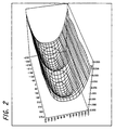
- FIG. 2 shows an ideal fluorescent screen shape obtained by simulation.
- the following expression 1 shows an example of a formula which defines the fluorescent screen shape, i.e., the panel inner surface shape of the cathode-ray tube 21 comprising the two electron guns 26 1 , 26 2 .
- the center of the screen of the cathode-ray tube 21 comprising two electron guns is defined as the origin O, the major axis direction of the screen (horizontal axis in this embodiment) being defined as the X-axis, the minor axis of the screen (vertical axis in this embodiment) being defined as the Y-axis and an axis which is perpendicular to both the X-axis and Y-axis being defined as the Z-axis, respectively (see FIG. 1).
- Z C1 • [1 + cos (X/X0 • ⁇ )] 2 + C2 • [1 + cos (X/X0 • ⁇ )] 4 + C3 • Y 2 + C4 • Y 4 + C5 • [1 + cos (X/X0 • ⁇ )] 2 • Y 2 + C6 • [1 + cos (X/X0 • ⁇ )] 2 • Y 4 + C7 • [1 + cos (X/X0 • ⁇ )] 4 • Y 2 + C8 • [1 + cos (X/X0 • ⁇ )] 4 • Y 4 where C1 to C8 are coefficients which depend on so-called tube types such as the size of a cathode-ray tube, the pitch of respective color fluorescent substance layers R, G, B of the fluorescent screen, intervals among the R, G, B beams at the deflection center, characteristics and positional relationship of the deflection yokes 30 [30 1 , 30 2 ] and the electron guns 26 [26
- X0 represents a constant which depends on the position on the axis of the electron gun 26 (position of the top of the curved surface), i.e., the distance from the origin O to the position on the axis of the electron gun 26 (see FIG. 1).
- the definition formula of this expression 1 is used, then its differential value is a continuous function so that the curved surface can be set to a smooth one.
- the fluorescent screen shape in the cathode-ray tube 21 comprising the two electron guns 26, i.e., the inner surface shape of the panel 22 can be made proper by setting up the panel inner surface shape so as to satisfy the expression 1.
- the following expression 2 shows another example of a formula which defines the fluorescent screen shape i.e., the panel inner surface shape of the cathode-ray tube 21 comprising the two electron guns 26 1 , 26 2 .
- the center of the screen of the cathode-ray tube including the two electron guns is defined as the origin O, the major axis of the screen (horizontal axis in this embodiment) being defined as the X-axis, the minor axis direction of the screen (vertical direction in this embodiment) being defined as the Y-axis and an axis which is perpendicular to both the X-axis and the Y-axis being defined as the Z-axis, respectively (see FIG. 1).
- Z (C1 + C2 •
- C1 to C18 are coefficients which depend on so-called tube types such as the size of a cathode-ray tube, the pitch of the respective color fluorescent substance layers R, G, B of the fluorescent screen, interval among the R, G, B beams at the deflection center, characteristics and positional relationship of the deflection yokes 30 [30 1 , 30 2 ] and the electron guns 26 [26 1 , 26 2 ] relative to the cathode-ray tube.
- the position of the top of the curved surface (position of X0 in FIG. 1) and the like can be set up freely, so that a target curved surface shape can be reproduced with a high accuracy by design.
- the fluorescent screen shape in the cathode-ray tube 21 comprising the two electron guns 26, i.e., the inner surface shape of the panel 22 can be made proper by setting up the panel inner surface shape so as to satisfy the expression 2.
- the following expression 3 shows a still another example of a formula which defines the fluorescent screen shape i.e., the panel inner surface shape of the cathode-ray tube 21 comprising the two electron guns 26 1 , 26 2 .
- the center of the screen of the cathode-ray tube 21 comprising two electron guns is defined as the origin O
- the major axis of the screen (horizontal axis in this embodiment) is defined as an X-axis
- the minor axis direction of the screen vertical axis in this embodiment) being defined as the Y-axis
- an axis which is perpendicular to both the X-axis and Y-axis being defined as the Z-axis, respectively (see FIG. 1).
- Z (C1 + C2 • X 2 + C3 • X 4 + C4 • X 6 + C5 • X 8 + C6 • X 10 ) + (C7 + C8 • X 2 + C9 • X 4 + C10 • X 6 + C11 • X 8 + C12 • X 10 ) • Y 2 + (C13 + C14 • X 2 + C15 • X 4 + C16 • X 6 + C17 • X 8 + C18 • X 10 ) • Y 4
- C1 to C18 are coefficients which depend on so-called tube types such as the size of a cathode-ray tube, the pitch of the respective color fluorescent substance layers R, G, B of the fluorescent screen, intervals among the R, G, B beams at the deflection center, characteristics and positional relationship of the deflection yokes 30 [30 1 , 30 2 ] and the electron guns 26 [26 1 , 26 2 ] relative to the cathode-ray tube.
- the fluorescent screen shape in the cathode-ray tube 21 comprising two electron guns 26, i.e., the inner surface shape of the panel 22 can be made proper by setting up the panel inner surface shape so as to satisfy the expression 3.
- FIG. 5 is a table diagram showing Z values of respective positions indicative of the fluorescent screen shape, i.e., the panel inner surface shape set up by the definition formula of the above expression 1 in a case where it is applied to a 36-inch type cathode-ray tube including two electron guns.
- C1 4. 6944 x 10 -1
- C2 - 4. 9464 x 10 -3
- C3 1. 2628 x 10 -4
- C4 -9. 3393 x 10 -11
- C5 - 2.
- FIG. 6 shows the panel inner surface shape obtained by simulation based on the Z values in FIG. 5.
- the fluorescent screen shape in the 36-inch type cathode-ray tube comprising the two electron guns can be made proper by setting up the panel inner surface shape so as to satisfy the expression 1.
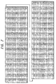
- FIG. 7 is a table diagram showing Z values of respective positions indicative of the fluorescent screen shape, i.e., the panel inner surface shape set up by the definition formula of the above expression 2 in a case where it is applied to a 36-inch type cathode-ray tube comprising two electron guns.
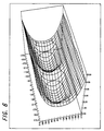
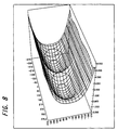
- FIG. 8 shows the panel inner surface shape obtained by simulation based on the values in FIG. 7.
- the fluorescent screen shape in the 36-inch type cathode-ray tube comprising the two electron guns can be made proper by setting up the panel inner surface shape so as to satisfy the expression 2.
- FIG. 9 is a table diagram showing Z values of respective positions indicative of the fluorescent screen shape, i.e., the panel inner surface shape set up by the definition formula of the above expression 3 in a case it is applied to a 36-inch type cathode-ray tube comprising two electron guns.
- FIG. 10 shows the panel inner surface shape obtained by simulation based on the values in FIG. 9.
- the fluorescent screen shape in the 36-inch type cathode-ray tube comprising the two electron guns can be made proper by setting up the panel inner surface shape so as to satisfy the expression 3.
- cathode-ray tube comprising the two electron guns
- present invention is not limited thereto and can also be applied to a cathode-ray tube comprising three or more of electron guns.
- the distance GH between the color-selection mechanism 28 and the color fluorescent screen 27 can be made proper, so that the respective color fluorescent substance layers R, G, B of the color fluorescent screen 27 can be disposed at equal intervals. Accordingly, it will be possible to display an image of high quality.
- the color fluorescent screen 27 can be manufactured with ease.
- the color fluorescent screen 27 can be manufactured more easily as compared with the case where the definition formulas (expressions 3 and 1) for determining the above fluorescent screen shapes are not used.
- the present invention is applied to the cathode-ray tube comprising a plurality of electron guns in which electron beams from the respective electron guns irradiate the respective small image areas so that the electron beams may partly overlap each other on the adjacent small image areas near the boundaries between the respective small image areas of the panel inner surface.
- the present invention is not limited thereto, and can also be applied to a cathode-ray tube in which electron beams from respective electron guns irradiate up to boundaries between respective small image areas of a panel inner surface so that electron beams may not overlap with each other on the adjacent small image areas.
- the distance between the color-selection mechanism and the fluorescent substance screen can be made proper and the respective color fluorescent layers of the color fluorescent screen can be regularly disposed with an equal interval. Accordingly, it will be possible to display an image of high quality. Moreover, the fluorescent screen can be manufactured with ease.
- the cathode-ray tube comprising a plurality of electron guns, in particularly, two electron guns, where its fluorescent screen shape is formed as a curved surface can be obtained by using the expressions 1, 2, and 3, of an ideal curved surface shape so that the image of the high quality can be provided.
- a color-selection mechanism including grid elements extending linearly in a horizontal direction and are arranged to form a curved surface shape in the vertical direction similar to the curved surface shape disposed relative to the fluorescent screen shape according to the present invention described above, and the distance between the color-selection mechanism and the fluorescent screen can be made proper.
- the present invention is suitably applied to the cathode-ray tube having the structure in which electron beams from the respective electron guns irradiate the respective small image areas so that the electron beams may partly overlap between the respective small image areas of the pas near boundaries inner surface each other on the adjacent small image areas boundaries.
Landscapes
- Vessels, Lead-In Wires, Accessory Apparatuses For Cathode-Ray Tubes (AREA)
- Electrodes For Cathode-Ray Tubes (AREA)
Applications Claiming Priority (2)
| Application Number | Priority Date | Filing Date | Title |
|---|---|---|---|
| JP2000180100 | 2000-06-15 | ||
| JP2000180100A JP3463654B2 (ja) | 2000-06-15 | 2000-06-15 | 陰極線管 |
Publications (2)
| Publication Number | Publication Date |
|---|---|
| EP1164626A2 true EP1164626A2 (fr) | 2001-12-19 |
| EP1164626A3 EP1164626A3 (fr) | 2004-01-07 |
Family
ID=18681262
Family Applications (1)
| Application Number | Title | Priority Date | Filing Date |
|---|---|---|---|
| EP01401571A Withdrawn EP1164626A3 (fr) | 2000-06-15 | 2001-06-15 | Tube à rayons cathodiques |
Country Status (5)
| Country | Link |
|---|---|
| US (1) | US20020041143A1 (fr) |
| EP (1) | EP1164626A3 (fr) |
| JP (1) | JP3463654B2 (fr) |
| KR (1) | KR20010112850A (fr) |
| CN (1) | CN1330388A (fr) |
Cited By (1)
| Publication number | Priority date | Publication date | Assignee | Title |
|---|---|---|---|---|
| WO2006073844A1 (fr) * | 2004-12-31 | 2006-07-13 | Thomson Licensing | Realisation d'un masque pour trc |
Families Citing this family (1)
| Publication number | Priority date | Publication date | Assignee | Title |
|---|---|---|---|---|
| KR20030060235A (ko) * | 2002-01-07 | 2003-07-16 | 삼성에스디아이 주식회사 | 멀티넥 음극선관 |
Family Cites Families (2)
| Publication number | Priority date | Publication date | Assignee | Title |
|---|---|---|---|---|
| DE19716933A1 (de) * | 1997-04-23 | 1998-10-29 | Reinhold Langguth Metallwarenf | Flache Bildröhre |
| EP0968515A1 (fr) * | 1997-12-23 | 2000-01-05 | Koninklijke Philips Electronics N.V. | Tube cathodique en couleur a au moins deux bobines de deviation et deux canons a electrons |
-
2000
- 2000-06-15 JP JP2000180100A patent/JP3463654B2/ja not_active Expired - Fee Related
-
2001
- 2001-06-14 US US09/880,148 patent/US20020041143A1/en not_active Abandoned
- 2001-06-14 KR KR1020010033506A patent/KR20010112850A/ko not_active Withdrawn
- 2001-06-15 CN CN01123393A patent/CN1330388A/zh active Pending
- 2001-06-15 EP EP01401571A patent/EP1164626A3/fr not_active Withdrawn
Cited By (1)
| Publication number | Priority date | Publication date | Assignee | Title |
|---|---|---|---|---|
| WO2006073844A1 (fr) * | 2004-12-31 | 2006-07-13 | Thomson Licensing | Realisation d'un masque pour trc |
Also Published As
| Publication number | Publication date |
|---|---|
| JP3463654B2 (ja) | 2003-11-05 |
| KR20010112850A (ko) | 2001-12-22 |
| US20020041143A1 (en) | 2002-04-11 |
| CN1330388A (zh) | 2002-01-09 |
| JP2001357799A (ja) | 2001-12-26 |
| EP1164626A3 (fr) | 2004-01-07 |
Similar Documents
| Publication | Publication Date | Title |
|---|---|---|
| CA1138518A (fr) | Canon electronique a region generatrice du faisceau reduisant la surluminance par astigmatisme | |
| KR100310404B1 (ko) | 컬러음극선관용섀도우마스크및그의제조방법 | |
| EP0899768A2 (fr) | Canon d'électrons de tube à rayons cathodique | |
| US20020041143A1 (en) | Cathode-ray tube | |
| JPH0536363A (ja) | 表示装置 | |
| US6157119A (en) | Shadow mask with improved color purity adjustment margin | |
| JP3927826B2 (ja) | 引張マスクに対する振動減衰部を有するcrt | |
| JP3082601B2 (ja) | シャドウマスク型カラー陰極線管 | |
| EP1361596B1 (fr) | Canon à électrons à disposition en ligne et tube à image couleur l'utilisant | |
| JP3222640B2 (ja) | カラー受像管装置 | |
| US6262526B1 (en) | Color Braun tube | |
| EP0755569B1 (fr) | Tube a rayons cathodiques de couleur comprenant un canon electronique en ligne | |
| JP4174365B2 (ja) | インライン型電子銃及びそれを用いたカラー受像管装置 | |
| JP2001307653A (ja) | カラー陰極線管 | |
| US6707241B2 (en) | Color cathode-ray tube | |
| JP3178943B2 (ja) | 受像管装置 | |
| JPH0778571A (ja) | カラー受像管 | |
| JP2001035407A (ja) | カラー陰極線管 | |
| JP2005510029A (ja) | 陰極線管のマスク・フレーム組み立て構体 | |
| JP2000090858A (ja) | 陰極線管 | |
| JP2000315470A (ja) | カラー陰極線管 | |
| JP2001297714A (ja) | カラー陰極線管 | |
| CN1015766B (zh) | 具有改进型荫罩架组件的彩色显象管 | |
| JP2001243891A (ja) | カラー陰極線管 | |
| JP2001110332A (ja) | カラー受像管 |
Legal Events
| Date | Code | Title | Description |
|---|---|---|---|
| PUAI | Public reference made under article 153(3) epc to a published international application that has entered the european phase |
Free format text: ORIGINAL CODE: 0009012 |
|
| AK | Designated contracting states |
Kind code of ref document: A2 Designated state(s): AT BE CH CY DE DK ES FI FR GB GR IE IT LI LU MC NL PT SE TR |
|
| AX | Request for extension of the european patent |
Free format text: AL;LT;LV;MK;RO;SI |
|
| PUAL | Search report despatched |
Free format text: ORIGINAL CODE: 0009013 |
|
| AK | Designated contracting states |
Kind code of ref document: A3 Designated state(s): AT BE CH CY DE DK ES FI FR GB GR IE IT LI LU MC NL PT SE TR |
|
| AX | Request for extension of the european patent |
Extension state: AL LT LV MK RO SI |
|
| AKX | Designation fees paid | ||
| REG | Reference to a national code |
Ref country code: DE Ref legal event code: 8566 |
|
| STAA | Information on the status of an ep patent application or granted ep patent |
Free format text: STATUS: THE APPLICATION IS DEEMED TO BE WITHDRAWN |
|
| 18D | Application deemed to be withdrawn |
Effective date: 20040708 |