EP1164656A2 - Système d'antenne et unité radio l'utilisant - Google Patents
Système d'antenne et unité radio l'utilisant Download PDFInfo
- Publication number
- EP1164656A2 EP1164656A2 EP01112580A EP01112580A EP1164656A2 EP 1164656 A2 EP1164656 A2 EP 1164656A2 EP 01112580 A EP01112580 A EP 01112580A EP 01112580 A EP01112580 A EP 01112580A EP 1164656 A2 EP1164656 A2 EP 1164656A2
- Authority
- EP
- European Patent Office
- Prior art keywords
- metallic plate
- mount type
- circuit board
- substrate
- radio unit
- Prior art date
- Legal status (The legal status is an assumption and is not a legal conclusion. Google has not performed a legal analysis and makes no representation as to the accuracy of the status listed.)
- Withdrawn
Links
Images


Classifications
-
- H—ELECTRICITY
- H01—ELECTRIC ELEMENTS
- H01Q—ANTENNAS, i.e. RADIO AERIALS
- H01Q23/00—Antennas with active circuits or circuit elements integrated within them or attached to them
-
- H—ELECTRICITY
- H01—ELECTRIC ELEMENTS
- H01Q—ANTENNAS, i.e. RADIO AERIALS
- H01Q1/00—Details of, or arrangements associated with, antennas
- H01Q1/36—Structural form of radiating elements, e.g. cone, spiral, umbrella; Particular materials used therewith
- H01Q1/38—Structural form of radiating elements, e.g. cone, spiral, umbrella; Particular materials used therewith formed by a conductive layer on an insulating support
-
- H—ELECTRICITY
- H01—ELECTRIC ELEMENTS
- H01Q—ANTENNAS, i.e. RADIO AERIALS
- H01Q1/00—Details of, or arrangements associated with, antennas
- H01Q1/12—Supports; Mounting means
- H01Q1/22—Supports; Mounting means by structural association with other equipment or articles
- H01Q1/24—Supports; Mounting means by structural association with other equipment or articles with receiving set
- H01Q1/241—Supports; Mounting means by structural association with other equipment or articles with receiving set used in mobile communications, e.g. GSM
- H01Q1/242—Supports; Mounting means by structural association with other equipment or articles with receiving set used in mobile communications, e.g. GSM specially adapted for hand-held use
- H01Q1/243—Supports; Mounting means by structural association with other equipment or articles with receiving set used in mobile communications, e.g. GSM specially adapted for hand-held use with built-in antennas
-
- H—ELECTRICITY
- H01—ELECTRIC ELEMENTS
- H01Q—ANTENNAS, i.e. RADIO AERIALS
- H01Q19/00—Combinations of primary active antenna elements and units with secondary devices, e.g. with quasi-optical devices, for giving the antenna a desired directional characteristic
- H01Q19/005—Patch antenna using one or more coplanar parasitic elements
-
- H—ELECTRICITY
- H01—ELECTRIC ELEMENTS
- H01Q—ANTENNAS, i.e. RADIO AERIALS
- H01Q9/00—Electrically-short antennas having dimensions not more than twice the operating wavelength and consisting of conductive active radiating elements
- H01Q9/04—Resonant antennas
- H01Q9/0407—Substantially flat resonant element parallel to ground plane, e.g. patch antenna
- H01Q9/0421—Substantially flat resonant element parallel to ground plane, e.g. patch antenna with a shorting wall or a shorting pin at one end of the element
Definitions
- the present invention relates to an antenna system mounted on a radio unit such as a portable telephone, and to a radio unit using this antenna system.
- Fig. 4 is a schematic perspective view showing an example of a surface-mount type antenna.
- the surface-mount type antenna 1 shown in Fig. 1 has a rectangular-parallelepiped shaped substrate 2 which is formed of a dielectric body.
- a radiation electrode 3 is formed on the top surface 2a of this substrate 2.
- the left end side (shown in Fig. 4) of the radiation electrode 3 is extended to a side surface 2b of the substrate 2, and the left end 3a of the radiation electrode 3 forms an open (unconnected) end.
- a feeding electrode 4 is extended from the bottom side toward the upper side, and is connected continuously to the right end portion of the radiation electrode 3, wrapping around the top surface 2a of the substrate 2.
- Such a surface-mount type antenna 1 is mounted on a circuit board, using the bottom surface 2d of the substrate 2 as a mounting surface, and is conductively connected to a radio unit circuitry 5 formed on the circuit board, via the feeding electrode 4.
- the radiation electrode 3 and the radio unit circuitry 5 thus conductively connected, for example, when a signal is supplied by the radio unit circuitry 5 to the radiation electrode 3 through the feeding electrode 4, the radiation electrode 3 is excited by the signal, and the signal (radio wave) is transmitted to the outside.
- the signal when a signal is received, the signal flows in the direction opposite to that during the above-described transmission, and the received signal is supplied to the radio unit 5. In this manner, the surface-mount type antenna 1 performs an antenna operation of transmitting/receiving the signal (radio wave).
- the frequency band is determined by the effective line length of the signal of the radiation electrode 3.
- the effective line length of the signal of the radiation electrode 3 is determined in accordance with the frequency band of the radio wave transmission/reception based upon a given specification.
- an antenna system 7 as shown in Fig. 5 has been proposed.
- the antenna system 7 is shown as being mounted on a circuit board 11 of a radio unit 10 such as a portable telephone.
- the antenna system 7 shown in Fig. 5 comprises a surface-mount type antenna 1 as described above which constitutes a surface-mount type antennas portion, and a metallic plate 8 which is conductively connected to the radiation electrode 3 of the surface-mount type antenna 1.
- the effective line length of the signal of the radiation electrode 3 is equivalently elongated by the increment of the installed metallic plate 8. This facilitates the transmission/ reception of radio waves at a required low frequency.
- the antenna system 7 is mounted on a circuit board 11 of a radio unit, for example, in an installation configuration as shown in Fig. 5.
- radio unit circuits (5) such as a signal processing circuit and a controlling circuit, are formed on the circuit board 11, and a shield case 13 for shielding these radio unit circuits is provided on this circuit board 11.
- the top surface of the shield case 13 is parallel with the surface of the circuit board 11 and the top surface 2a and the bottom surface 2d of the substrate 2 of the surface-mount type antenna 1.
- the surface-mount type antenna 1 of the antenna system 7 is mounted on the circuit board 11 in the vicinity of the shield case 13, using the bottom surface 2d of the substrate 2 of the surface-mount type antenna 1 as a mounting surface.
- the metallic plate 8 of the antenna system 7 is disposed above the shield case 13 with a space therebetween so that the surface of the metallic plate 8 is parallel with the top surface of the shield case 13.
- the circuit board 11 on which the antenna system 7 and the radio unit circuits are provided, are housed in, for example, a case 12 as shown by a chain line in Fig. 5.
- a battery for power in the radio unit is disposed on the blank portion on the circuit board 11 as shown in Fig. 5.
- the spacing between the metallic plate 8 of the antenna system 7 and the top surface of the shield case 13 must be made very narrow.
- the entire surface of the metallic plate 8 is opposed to the top surface of the shield case 13 with a space therewith, and the shield case 13 and the surface of the circuit board 11 are equivalent to the ground, and hence, by reducing the spacing between the metallic plate 8 and the shield case 13 as described above, the electrostatic capacitance between the metallic plate 8 and the shield case 13, in other words, the electrostatic capacitance between the metallic plate 8 and the ground, significantly increases.
- This increase in the capacitance causes problems such as a reduction in the antenna gain, and the narrowing of the frequency bandwidth of radio wave transmission/reception.
- a surface-mount type antenna which comprises a surface-mount type antenna portion which is configured by forming, on a substrate, a radiation electrode for radio wave transmission/reception, and a metallic plate which is conductively connected to the radiation electrode of the surface-mount type antenna portion, and which performs radio wave transmission/reception together with the radiation electrode.
- the surface-mount type antenna portion is mounted on a circuit board of a radio unit, using the bottom surface of the substrate as a mounting surface, and the metallic plate is provided so as to be isolated from the circuit board.
- the metallic plate is preferably disposed adjacent to the long-side surface of the substrate of the surface-mount type antenna portion with a space therebetween so that the surface of the metallic plate is non-parallel with the bottom surface of the surface-mount type antenna portion.
- the present invention provides, in a second aspect, a radio unit which includes an antenna system in accordance with the above-described first aspect.
- the metallic plate of the antenna system be disposed so that the surface thereof is opposed to the corresponding end surface of a circuit board with a spacing therebetween.
- the metallic plate of the antenna system is disposed adjacent to the outer long-side surface of the substrate of the surface-mount type antenna portion with a space therebetween so that the surface of the metallic plate is non-parallel with the bottom surface of the surface-mount type antenna portion.
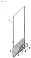
- Fig. 1 shows a radio unit in accordance with an embodiment of the present invention, together with an antenna system in accordance with an embodiment thereof.
- the radio unit 10 shown in this embodiment is also provided with a case 12 as shown in Fig. 5, but the illustration of the case is omitted in Fig. 1.
- the antenna system 7 in accordance with this embodiment comprises a surface-mount type antenna 1 which constitutes a surface-mount type antenna portion as in the case of the antenna system 7 shown in Fig. 5, and a metallic plate.
- the difference between the antenna system in accordance with this embodiment and the antenna system shown in Fig. 5 is characterized by the installation relation between the above-described surface-mount type antenna 1 and the metallic plate 8.
- the metallic plate 8 is disposed adjacent to the outer long-side surface of the substrate 2 of the surface-mount type antenna 1 with a space therebetween so that the surface of the metallic plate 8 is substantially parallel with the side surface of the substrate 2.
- the surface-mount type antenna 1 may have various configurations, but herein, descriptions will be given, taking the surface-mount type antenna 1 shown in Fig. 4 as an example.
- a metallic plate member for connection 14 is extended in the direction perpendicular to the plane of the metallic plate 8 from the upper end 8a (shown in Fig. 1) of the metallic plate 8, and the extending tip of the metallic plate member for connection 14 is bonded to the radiation electrode 3 of the surface-mount type antenna 1, using solder or a conductive adhesive.
- the radiation electrode 3 and the metallic plate 8 are thereby conductively connected.
- the upper end portion 8a of the metallic plate 8 is disposed substantially flush with the top surface of the substrate 2 of the surface-mount type antenna 1.
- the radio unit 10 in accordance with this embodiment is provided with the antenna system 7 which has the above-described peculiar feature at the outer edge region of the circuit board 11. More specifically, the surface-mount type antenna 1 of the antenna system 7 is mounted at the outer edge region of the circuit board 11, using the bottom surface 2d of the substrate 2 as a mounting surface.
- the metallic plate 8 lies off the circuit board 11, that is, the metallic plate 8 is disposed so as to be isolated from the circuit board, with a space interposed therebetween.
- the lower end 8d of the metallic plate is located at a lower position than the bottom surface 2d of the substrate 2 of the surface-mount type antenna I, and more specifically, for example, substantially at a position on the same level with the rear surface of the circuit board 11, or a position slightly projecting downward with respect to the rear surface, that is, a position lower than the top portion of the tallest component of the components provided on the rear surface.
- the surface of the metallic plate 8 becomes opposed not only to the outer long-side surface of the substrate 2 but also to the corresponding end surface of the circuit board 11, with a space therebetween.
- the upper end 8a of the metallic plate 8 is on the same level as the top surface of the substrate 2 of the surface-mount type antenna 1, and the lower end 8d of the metallic plate 8 is on the same level as the rear surface of the circuit board 11, or slightly projecting downward with respect to the rear surface.
- the width in the height direction of the metallic plate 8 is small, and as shown in Fig. 1, the metallic plate 8 preferably has a narrow rectangular shape. In this manner, by reducing the width in the height direction of the metallic plate 8, the end portion of the metallic plate 8 is prevented from projecting in the vertical direction (shown in Fig. 1) with respect to the other components of the radio unit 10. In other words, the metallic plate 8 has a configuration not hindering the reduction in thickness of the radio unit 10.
- the spacing between the metallic plate 8 and the corresponding side surface of the shield case 13 is set to be sufficiently wide to prevent the occurrence of the problem of the increase in electrostatic capacitance between the metallic plate 8 and the ground.
- the antenna system 7 is formed by conductively connecting the metallic plate 8 to the radiation electrode 3 of the surface-mount type antenna 1, the effective line length of the signals of the radiation electrode 3 can be equivalently elongated.
- This facilitate obtaining an antenna system 7 capable of transmitting/receiving low-frequency radio waves, which is difficult to be obtained by the radiation electrode 3 alone.
- One possible means for equivalently elongating the effective line length of the signals of the radiation electrode 3 without utilizing the metallic plate 8, is to connect an inductance component in series with the radiation electrode 3. This, however, creates a problem that the antenna sensitivity is deteriorated by the inductance component.
- the metallic plate 8 is disposed adjacent to the outer long-side surface of the substrate 2 of the surface-mount type antenna 1 with a space therebetween so that the surface of the metallic plate is substantially parallel with the outer long-side surface of the substrate 2, the metallic plate 8 becomes substantially perpendicular to the surface of the circuit board 11 and the top surface of the shield case 13 when the antenna system 7 is mounted on the circuit board 11 of the radio unit 10 in the embodiment shown in Fig. 1.
- the occurrence of a large electrostatic capacitance between the surface of the circuit board or the top surface of the shield case 13 and the metallic plate 8 can be prevented.
- the antenna system 7 having a configuration in accordance with this embodiment exhibits a significant improvement in the antenna gain and an enlargement in the bandwidth, relative to the antenna system 7 in accordance with the proposed example.
- providing the antenna system 7 having a configuration according to this embodiment suppresses the deterioration of the antenna performance such as the antenna gain and the bandwidth, and allows the slimming of the radio unit 10 to be achieved.
- the present invention is not limited to the above-described embodiment, but various embodiments may be adopted.
- the metallic plate 8 is disposed substantially parallel with the outer long-side surface of the substrate 2 of the surface-mount type antenna 1, the metallic plate 8 has only to be disposed non-parallel with the bottom surface of the substrate 2, that is, the metallic plate 8 may be disposed so as to be tilted with respect to the outer long-side surface of the substrate 2.
- the metallic plate member for connection 14 for the metallic plate 8 and the radiation electrode 3 are bonded using solder or a conductive adhesive.
- the metallic plate 8 and the radiation electrode 3 only need to be conductively connected, and hence, the metallic plate 8 and the radiation electrode 3, for example, have only to be in contact without bonding them, or may be made integral, for example.
- the lower end 8d of the metallic plate 8 is located lower than the bottom surface 2d of the substrate 2 of the surface-mount type antenna 1, but may be located on the same level with the bottom surface 2d of the substrate 2, or higher than the bottom surface 2d. Also, in the above-described embodiment, the metallic plate 8 is disposed so as to lie off the circuit board 11, but may be disposed above the circuit board 11 with a space therebetween.
- a surface-mount type antenna 1 as shown in Fig. 4, as an example, but the configuration of the surface mount type antenna portion constituting an antenna system in accordance with the present invention is not restricted to that of the surface-mount type antenna shown in Fig. 4.
- the surface mount type antenna portion may have various configurations.
- a surface-mount type antenna as shown in Fig. 2A may be adopted.
- Fig. 2B is an exploded view of the surface-mount type antenna shown in Fig. 2A.
- the surface-mount type antenna 1 shown in Figs. 2A and 2B has a substrate 2 which is formed by integrally laminating sheet layers 16a, 16b, and 16c constituted of a dielectric material. Within this substrate 2, a radiation electrode 3 formed into a spiral shape is disposed. Specifically, on the top surface of each of the sheet layers 16a and 16b constituting the substrate 2, conductive patterns 17 and 18 for forming the above-described radiation electrode 3 are formed, respectively. The conductive pattern 17 formed on the sheet layer 16a and the conductive pattern 18 formed on the sheet layer 16b are conductively connected via a through hole formed through the sheet layer 16b, thereby forming the spiral-shaped radiation electrode 3.
- a feeding electrode 4 is formed on the left side surface (shown in Fig. 2A) of the substrate 2, and a free terminal portion 20 is formed on the right side surface shown in Fig. 2A.
- One end side of the radiation electrode 3 is conductively connected to the above-described feeding electrode 4, while the other end of the radiation electrode 3 is conductively connected to the free terminal portion 20.
- a surface-mount type antenna 1 as shown in Fig. 3A may be adopted.
- the surface-mount type antenna 1 shown in Fig. 3A is such that the radiation electrode 3 is configured by forming spiral-shaped conductor patterns on the top surface, the front side-surface, the bottom surface, and the rear side-surface of the substrate 2.
- one end side of the radiation electrode 3 is conductively connected to the feeding electrode 4 formed on the left side- surface of the substrate 2, while the other end of the radiation electrode 3 is conductively connected to the free terminal portion 20 formed on the right side-surface of the substrate 2.
- a surface-mount type antenna 1 as shown in Fig. 3B may be adopted.
- the surface-mount type antenna 1 shown in Fig. 3B is such that the radiation electrode 3 is configured by forming meander-shaped conductor patterns on the top surface of the substrate 2.
- one end side of the radiation electrode 3 is conductively connected to the feeding electrode 4 formed on the substrate 2, while the other end side of the radiation electrode 3 is conductively connected to the free terminal portion 20 formed on the substrate 2.
- Each of the surface-mount type antennas 1 shown in Figs. 2A and 2B, and Figs. 3A and 3B can also perform the function similar to that of surface-mount type antenna 1 in accordance with the above-described embodiment, by mounting the surface-mount type antenna 1 on the circuit board 11 of the radio unit 10, and conductively connecting the radio unit 5 to the above-described feeding electrode 4.
- a similar antenna system to the above-described embodiment can be configured.
- a metallic plate is conductively connected to the free terminal portion 20 of each of the surface-mount type antennas 1 shown in Figs. 2A and 2B, and Figs. 3A, 3B, and the radiation electrode 3 and the metallic plate are conductively connected via the free terminal portion 20.
- the metallic plate is disposed adjacent to the outer long-side surface of the substrate with a space therebetween so as to be non-parallel with the bottom surface 2d of the substrate 2.
- the substrate 2 constituting a surface-mount type antenna 1 is formed of a dielectric body, but the substrate may instead be formed of, for example, a magnetic body.
- the metallic plate to be conductively connected to the radiation electrode of the surface-mount type antenna portion is disposed adjacent to the outer long-side surface of the substrate of the surface-mount type antenna portion with a space therebetween so that the surface of the metallic plate is non-parallel with the bottom surface of the surface-mount type antenna portion, it is possible to prevent an occurrence of a large electrostatic capacitance between the surface of the circuit board surface, which is equivalent to ground, and the metallic plate, when mounting the surface-mount type antenna portion of the antenna system on the circuit board using the bottom surface of the substrate as a mounting surface. Thereby, the reduction in antenna gain and the narrowing of bandwidth due to the increase in electrostatic capacitance between the metallic plate and ground can be prevented.
- the radio unit of the present invention since an antenna system having the described features is provided in this radio unit, a reduction in the thickness of the radio can be achieved without a corresponding reduction in antenna gain and narrowing of bandwidth.
- the metallic plate of the antenna system thereof is disposed so that the surface thereof is opposed to the corresponding end surface of the circuit board with a space therebetween, the metallic plate and the surface of the circuit board do not face each other, and hence, it is possible to reduce the problem of the increase in electrostatic capacitance between the metallic plate and ground, and to achieve a low-profile radio unit which has a superior antenna gain, and which allows widening of the frequency band of radio wave transmission/reception to be achieved.
Landscapes
- Engineering & Computer Science (AREA)
- Computer Networks & Wireless Communication (AREA)
- Support Of Aerials (AREA)
- Details Of Aerials (AREA)
- Telephone Set Structure (AREA)
- Waveguide Aerials (AREA)
Applications Claiming Priority (2)
| Application Number | Priority Date | Filing Date | Title |
|---|---|---|---|
| JP2000179980A JP2001358517A (ja) | 2000-06-15 | 2000-06-15 | アンテナ装置およびそれを用いた無線機 |
| JP2000179980 | 2000-06-15 |
Publications (2)
| Publication Number | Publication Date |
|---|---|
| EP1164656A2 true EP1164656A2 (fr) | 2001-12-19 |
| EP1164656A3 EP1164656A3 (fr) | 2003-12-17 |
Family
ID=18681158
Family Applications (1)
| Application Number | Title | Priority Date | Filing Date |
|---|---|---|---|
| EP01112580A Withdrawn EP1164656A3 (fr) | 2000-06-15 | 2001-05-23 | Système d'antenne et unité radio l'utilisant |
Country Status (5)
| Country | Link |
|---|---|
| US (1) | US6433746B2 (fr) |
| EP (1) | EP1164656A3 (fr) |
| JP (1) | JP2001358517A (fr) |
| KR (1) | KR100414635B1 (fr) |
| CN (1) | CN1156127C (fr) |
Families Citing this family (32)
| Publication number | Priority date | Publication date | Assignee | Title |
|---|---|---|---|---|
| US6606072B1 (en) | 2000-07-06 | 2003-08-12 | Stata Labs, Llc | Antenna design using a slot architecture for global positioning system (GPS) applications |
| US6720923B1 (en) * | 2000-09-14 | 2004-04-13 | Stata Labs, Llc | Antenna design utilizing a cavity architecture for global positioning system (GPS) applications |
| US6618011B2 (en) * | 2000-10-13 | 2003-09-09 | Nokia Corporation | Antenna transducer assembly, and an associated method therefor |
| KR20020061103A (ko) * | 2001-01-12 | 2002-07-22 | 후루까와덴끼고오교 가부시끼가이샤 | 안테나 장치 및 이 안테나 장치가 부착된 단말기기 |
| JP2002314330A (ja) * | 2001-04-10 | 2002-10-25 | Murata Mfg Co Ltd | アンテナ装置 |
| KR100423396B1 (ko) * | 2001-07-02 | 2004-03-18 | 삼성전기주식회사 | 칩 안테나 |
| JP2003101332A (ja) * | 2001-09-20 | 2003-04-04 | Kyocera Corp | アンテナ装置 |
| JP2003198410A (ja) * | 2001-12-27 | 2003-07-11 | Matsushita Electric Ind Co Ltd | 通信端末装置用アンテナ |
| KR20040000535A (ko) * | 2002-06-21 | 2004-01-07 | (주)컴뮤웍스 | 이동 통신 단말기의 내장형 gps안테나 |
| JP3713476B2 (ja) | 2002-09-10 | 2005-11-09 | 株式会社東芝 | 移動通信端末 |
| ATE545173T1 (de) * | 2002-12-22 | 2012-02-15 | Fractus Sa | Mehrband-monopolantenne für ein mobilfunkgerät |
| TW583783B (en) * | 2003-04-17 | 2004-04-11 | Htc Corp | Perpendicularly-oriented inverted F antenna |
| TW558078U (en) * | 2003-05-20 | 2003-10-11 | Hon Hai Prec Ind Co Ltd | Antenna |
| JP4105987B2 (ja) * | 2003-06-24 | 2008-06-25 | 京セラ株式会社 | アンテナおよびアンテナモジュールおよびそれを具備した無線通信装置 |
| JP2005175665A (ja) * | 2003-12-09 | 2005-06-30 | Matsushita Electric Ind Co Ltd | アンテナモジュール |
| GB2409935B (en) * | 2004-01-09 | 2007-02-28 | Zarlink Semiconductor Ltd | Electronic assembly |
| US7629928B2 (en) * | 2005-03-23 | 2009-12-08 | Kyocera Wireless Corp. | Patch antenna with electromagnetic shield counterpoise |
| JP2007123982A (ja) * | 2005-10-25 | 2007-05-17 | Sony Ericsson Mobilecommunications Japan Inc | マルチバンド対応アンテナ装置および通信端末装置 |
| US8044860B2 (en) * | 2005-11-23 | 2011-10-25 | Industrial Technology Research Institute | Internal antenna for mobile device |
| JP4808554B2 (ja) * | 2006-06-28 | 2011-11-02 | 京セラ株式会社 | 無線通信端末 |
| KR100870915B1 (ko) | 2006-10-24 | 2008-11-28 | 한국표준과학연구원 | 무선센서복합체의 정전기 보호용 방전 유도로 구조 |
| DE102009051605B4 (de) * | 2009-11-02 | 2022-08-18 | Continental Automotive Gmbh | Hochintegrierte Multiband-Finnenantenne für ein Fahrzeug |
| JP4853569B2 (ja) * | 2009-11-13 | 2012-01-11 | パナソニック株式会社 | アンテナモジュール |
| CN104580565B (zh) * | 2013-10-22 | 2018-07-03 | 联想(北京)有限公司 | 移动通讯设备 |
| JP5726983B2 (ja) * | 2013-10-30 | 2015-06-03 | 太陽誘電株式会社 | チップ状アンテナ装置及び送受信用通信回路基板 |
| KR20160030672A (ko) * | 2014-09-11 | 2016-03-21 | 삼성전기주식회사 | 무선 전력 수신 장치 및 무선 전력 송수신 시스템 |
| FR3051063B1 (fr) * | 2016-05-06 | 2021-02-12 | Linxens Holding | Procede de fabrication de cartes a puce et carte a puce obtenue par ce procede |
| CN106025518B (zh) * | 2016-06-28 | 2019-05-28 | 深圳市信维通信股份有限公司 | 一种无线通信装置 |
| US10476170B2 (en) | 2018-02-27 | 2019-11-12 | Apple Inc. | Antenna arrays having conductive shielding buckets |
| CN109040352B (zh) * | 2018-06-12 | 2020-06-23 | Oppo广东移动通信有限公司 | 天线位置调整方法、装置、移动终端以及存储介质 |
| CN108989511B (zh) * | 2018-09-25 | 2023-05-12 | 苏州昀冢电子科技股份有限公司 | 一种具有电子元件的基座及音圈马达 |
| JP6969531B2 (ja) * | 2018-10-10 | 2021-11-24 | オムロン株式会社 | 電子機器 |
Family Cites Families (11)
| Publication number | Priority date | Publication date | Assignee | Title |
|---|---|---|---|---|
| JP3114621B2 (ja) * | 1996-06-19 | 2000-12-04 | 株式会社村田製作所 | 表面実装型アンテナおよびこれを用いた通信機 |
| US5764190A (en) * | 1996-07-15 | 1998-06-09 | The Hong Kong University Of Science & Technology | Capacitively loaded PIFA |
| JPH1098322A (ja) * | 1996-09-20 | 1998-04-14 | Murata Mfg Co Ltd | チップアンテナ及びアンテナ装置 |
| JP3279205B2 (ja) * | 1996-12-10 | 2002-04-30 | 株式会社村田製作所 | 表面実装型アンテナおよび通信機 |
| JPH11168317A (ja) * | 1997-12-03 | 1999-06-22 | Murata Mfg Co Ltd | チップアンテナ |
| JPH11205025A (ja) * | 1998-01-14 | 1999-07-30 | Murata Mfg Co Ltd | チップアンテナ |
| US6288680B1 (en) * | 1998-03-18 | 2001-09-11 | Murata Manufacturing Co., Ltd. | Antenna apparatus and mobile communication apparatus using the same |
| FR2778500B1 (fr) * | 1998-05-05 | 2000-08-04 | Socapex Amphenol | Antenne a plaque |
| JP2000114856A (ja) * | 1998-09-30 | 2000-04-21 | Nec Saitama Ltd | 逆fアンテナおよびそれを用いた無線装置 |
| JP3554960B2 (ja) * | 1999-06-25 | 2004-08-18 | 株式会社村田製作所 | アンテナ装置およびそれを用いた通信装置 |
| JP3646782B2 (ja) * | 1999-12-14 | 2005-05-11 | 株式会社村田製作所 | アンテナ装置およびそれを用いた通信機 |
-
2000
- 2000-06-15 JP JP2000179980A patent/JP2001358517A/ja active Pending
-
2001
- 2001-05-23 EP EP01112580A patent/EP1164656A3/fr not_active Withdrawn
- 2001-06-01 US US09/872,101 patent/US6433746B2/en not_active Expired - Fee Related
- 2001-06-14 KR KR10-2001-0033440A patent/KR100414635B1/ko not_active Expired - Fee Related
- 2001-06-15 CN CNB011210729A patent/CN1156127C/zh not_active Expired - Fee Related
Also Published As
| Publication number | Publication date |
|---|---|
| EP1164656A3 (fr) | 2003-12-17 |
| JP2001358517A (ja) | 2001-12-26 |
| US6433746B2 (en) | 2002-08-13 |
| CN1156127C (zh) | 2004-06-30 |
| US20020008666A1 (en) | 2002-01-24 |
| KR100414635B1 (ko) | 2004-01-07 |
| CN1330477A (zh) | 2002-01-09 |
| KR20010113012A (ko) | 2001-12-24 |
Similar Documents
| Publication | Publication Date | Title |
|---|---|---|
| US6433746B2 (en) | Antenna system and radio unit using the same | |
| US5537123A (en) | Antennas and antenna units | |
| US7916086B2 (en) | Antenna component and methods | |
| US6268831B1 (en) | Inverted-f antennas with multiple planar radiating elements and wireless communicators incorporating same | |
| US6288680B1 (en) | Antenna apparatus and mobile communication apparatus using the same | |
| US6097339A (en) | Substrate antenna | |
| EP1139490B1 (fr) | Antenne montee en surface et dispositif de communication dote d'une antenne montee en surface | |
| EP1248316B1 (fr) | Antenne et appareil de communication muni de cette antenne | |
| US7119749B2 (en) | Antenna and radio communication apparatus | |
| US6429818B1 (en) | Single or dual band parasitic antenna assembly | |
| US7148847B2 (en) | Small-size, low-height antenna device capable of easily ensuring predetermined bandwidth | |
| US7786940B2 (en) | Antenna structure and wireless communication device including the same | |
| EP1128467B1 (fr) | Dispositif d'antenne | |
| KR20000076272A (ko) | 통신 장치용 안테나 어셈블리 | |
| CN109473787B (zh) | 一种鲨鱼鳍天线组件 | |
| US20240347903A1 (en) | Antenna Structure and Electronic Device | |
| EP1316126B1 (fr) | Dispositif d'antenne | |
| JPH10247806A (ja) | 携帯無線機用アンテナおよびそれを用いた携帯無線機 | |
| US20050174296A1 (en) | Antenna and wireless communications device having antenna | |
| JP3467164B2 (ja) | 逆fアンテナ | |
| JPH08111609A (ja) | アンテナ装置 | |
| CA2321214C (fr) | Antenne de substrat | |
| JPH09232854A (ja) | 移動無線機用小型平面アンテナ装置 | |
| JP2003124830A (ja) | 複合アンテナ | |
| JPH07288421A (ja) | 平面アンテナ |
Legal Events
| Date | Code | Title | Description |
|---|---|---|---|
| PUAI | Public reference made under article 153(3) epc to a published international application that has entered the european phase |
Free format text: ORIGINAL CODE: 0009012 |
|
| 17P | Request for examination filed |
Effective date: 20010523 |
|
| AK | Designated contracting states |
Kind code of ref document: A2 Designated state(s): AT BE CH CY DE DK ES FI FR GB GR IE IT LI LU MC NL PT SE TR |
|
| AX | Request for extension of the european patent |
Free format text: AL;LT;LV;MK;RO;SI |
|
| PUAL | Search report despatched |
Free format text: ORIGINAL CODE: 0009013 |
|
| AK | Designated contracting states |
Kind code of ref document: A3 Designated state(s): AT BE CH CY DE DK ES FI FR GB GR IE IT LI LU MC NL PT SE TR |
|
| AX | Request for extension of the european patent |
Extension state: AL LT LV MK RO SI |
|
| RIC1 | Information provided on ipc code assigned before grant |
Ipc: 7H 01Q 1/40 B Ipc: 7H 01Q 1/36 B Ipc: 7H 01Q 1/24 B Ipc: 7H 01Q 1/38 A |
|
| AKX | Designation fees paid |
Designated state(s): DE FR GB |
|
| 17Q | First examination report despatched |
Effective date: 20040810 |
|
| GRAP | Despatch of communication of intention to grant a patent |
Free format text: ORIGINAL CODE: EPIDOSNIGR1 |
|
| STAA | Information on the status of an ep patent application or granted ep patent |
Free format text: STATUS: THE APPLICATION IS DEEMED TO BE WITHDRAWN |
|
| 18D | Application deemed to be withdrawn |
Effective date: 20051005 |