EP1164663B1 - Befestigungstruktur eines Verbindergehäuses und einer von hinten angebrachten Kontakthalterung - Google Patents
Befestigungstruktur eines Verbindergehäuses und einer von hinten angebrachten Kontakthalterung Download PDFInfo
- Publication number
- EP1164663B1 EP1164663B1 EP01304827A EP01304827A EP1164663B1 EP 1164663 B1 EP1164663 B1 EP 1164663B1 EP 01304827 A EP01304827 A EP 01304827A EP 01304827 A EP01304827 A EP 01304827A EP 1164663 B1 EP1164663 B1 EP 1164663B1
- Authority
- EP
- European Patent Office
- Prior art keywords
- connector housing
- rear holder
- terminal
- rear holders
- housing
- Prior art date
- Legal status (The legal status is an assumption and is not a legal conclusion. Google has not performed a legal analysis and makes no representation as to the accuracy of the status listed.)
- Expired - Lifetime
Links
- 239000002184 metal Substances 0.000 claims description 21
- 230000000717 retained effect Effects 0.000 claims description 16
- 229920005989 resin Polymers 0.000 claims description 10
- 239000011347 resin Substances 0.000 claims description 10
- 238000000465 moulding Methods 0.000 description 54
- 238000004519 manufacturing process Methods 0.000 description 3
- 238000000034 method Methods 0.000 description 3
- 230000014759 maintenance of location Effects 0.000 description 2
- 239000002699 waste material Substances 0.000 description 2
- 208000019901 Anxiety disease Diseases 0.000 description 1
- 230000036506 anxiety Effects 0.000 description 1
- 238000010276 construction Methods 0.000 description 1
- 230000002950 deficient Effects 0.000 description 1
- 238000003780 insertion Methods 0.000 description 1
- 230000037431 insertion Effects 0.000 description 1
- 238000012986 modification Methods 0.000 description 1
- 230000004048 modification Effects 0.000 description 1
- 239000010813 municipal solid waste Substances 0.000 description 1
- 229920003002 synthetic resin Polymers 0.000 description 1
- 239000000057 synthetic resin Substances 0.000 description 1
Images


Classifications
-
- H—ELECTRICITY
- H01—ELECTRIC ELEMENTS
- H01R—ELECTRICALLY-CONDUCTIVE CONNECTIONS; STRUCTURAL ASSOCIATIONS OF A PLURALITY OF MUTUALLY-INSULATED ELECTRICAL CONNECTING ELEMENTS; COUPLING DEVICES; CURRENT COLLECTORS
- H01R13/00—Details of coupling devices of the kinds covered by groups H01R12/70 or H01R24/00 - H01R33/00
- H01R13/40—Securing contact members in or to a base or case; Insulating of contact members
- H01R13/42—Securing in a demountable manner
- H01R13/436—Securing a plurality of contact members by one locking piece or operation
- H01R13/4361—Insertion of locking piece perpendicular to direction of contact insertion
- H01R13/4362—Insertion of locking piece perpendicular to direction of contact insertion comprising a temporary and a final locking position
Definitions
- the present invention relates to a structure for engaging a connector housing and a rear holder which are molded and engaged with each other in a same metal mold.
- a connector housing disclosed in the above mentioned publication has such an outer shape that its backward part beyond a middle part in a longitudinal direction is dimensioned a little smaller than its forward part, and rear holders (corresponding to "retainers" in the above mentioned publication, which are members contributing to retention of terminals which are contained in the connector housing) formed in a substantially U-shape in sectional view are adapted to be engaged with the smaller dimensioned part.
- the connector housing and the rear holders are constructed in such a manner that the rear holders can be engaged with the connector housing temporarily as well as completely. Processes until the rear holders are temporarily retained with the connector housing are intended to be performed in the same metal mold.
- EP-A-0733463 which is considered to represent the closest prior art discloses a resin molded connector assembly which has the problem that engagement is not easily performed.
- EP-A-0739054 discloses an electrical connector retainer.
- the present invention has been made in view of the above described circumstances, and it is an object of the present invention to provide a structure for engaging a connector housing and a rear holder molded in a same metal mold, enabling the rear holder to be reliably engaged with the connector housing and ensuring smooth movement of the rear holder.
- a structure for engaging a connector housing and a rear holder which are molded and assembled to engage with each other in a same metal mold comprising:
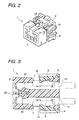
- a connector represented by reference numeral 1 includes a connector housing 2 in a rectangular box-like shape, and rear holders 3, 4 in a substantially U-shape in sectional view and adapted to be fitted respectively to an upper surface and a lower surface of the connector housing 2 (The connector housing 2 and the rear holders 3, 4 are products of synthetic resin molded in a same metal mold which will be described below).
- the connector housing 2 has terminal receiving chambers 5 in two rows in an upper section and in four rows in a lower section.
- the terminal receiving chambers 5 in the upper section are formed on both left and right sides of the connector housing 2, and in a center of the connector housing 2, there is formed a lock arm 6 which is flexible in a vertical direction.
- the connector housing 2 is formed so as to have a slightly smaller outer shape in its backward part beyond a longitudinally middle part of the connector housing 2 than its forward part. With this smaller dimensioned part, the rear holders 3, 4 are adapted to be engaged.
- terminal retaining holes 7 which open upward and downward respectively.
- Each of the terminal retaining holes 7 is so formed as to communicate with each of the terminal receiving chambers 5.
- the smaller dimensioned part has on both side surfaces thereof four guide rails 8 (guide rails for temporary retainment) in a form of a ridge corresponding to the rear holders 3, 4, four small projections 9 (projections for complete retainment), and a pair of left and right protrusions 10.
- a backward end of the connector housing 2 is provided with tapered surfaces 11 which are inclined toward its side surfaces. The tapered surfaces 11 are formed in order that the engagement of the rear holders 3, 4 can be reliably performed.
- the backward end portion of the connector housing 2 serves as a portion for positioning the rear holders with respect to the connector housing.
- the guide rails 8 are diagonally formed on the aforesaid side surfaces so as to be directed toward a center part in a vertical direction as they extend in a direction toward a forward end of the connector housing 2 .
- the guide rails 8 are respectively provided with tapered surfaces 12 along their longitudinal direction.
- the tapered surfaces 12 are formed on the sides opposed to the rear holders 3, 4 so that the engagement of the rear holders 3, 4 can be reliably conducted (The temporary engagement of the rear holders 3, 4 can be smoothly performed).
- the small projections 9 are formed at forward positions in extended lines of the guide rails 8.
- the protrusions 10 are formed inside of the guide rails 8 and the small projections 9 diagonally in parallel therewith, and protrude in a V-shape to have a same width as the forward part of the connector housing 2.
- the rear holders 3, 4 are formed substantially symmetrically as a whole.
- the rear holders 3, 4 have a pair of wings 13, 13 respectively and are formed in such a manner that when respective openings (open sides) in a substantially U-shape in sectional view are drawn near to the connector housing 2, the pair of the wings 13, 13 may clamp the smaller dimensioned part of the connector housing 2 from both sides.
- the wings 13 are diagonally formed so as to go along the protrusions 10.
- the wings 13 are provided with guide grooves 14 into which the guide rails 8 and the small projections 9 are adapted to enter.
- the guide grooves 14 are formed so as to correspond to the inclination of the guide rails 8 and the small projections 9.
- the wings 13, 13 have tapered surfaces 15 at inner surfaces of their distal ends respectively. These tapered surfaces 15 allow the rear holders 3, 4 to be reliably engaged with the connector housing 2, because the tapered surfaces 15 will prevent the wings 13, 13 from striking the connector housing 2 and causing defective engagement.
- the rear holders 3, 4 are formed shorter than the smaller dimensioned part of the connector housing 2. Accordingly, when the rear holders 3, 4 are engaged with the connector housing 2 in a clamping manner from the upper and the lower surface sides, the guide rails 8 enter in the guide grooves 14, thereby enabling the rear holders 3, 4 to slide back and forth along the connector housing 2. Meanwhile, the rear holders 3, 4 are drawn near to and apart from the connector housing 2 while moving back and forth, since the wings 13, 13 of the rear holders 3, 4 are formed diagonally. At the forward end in a moving extent of the rear holders 3, 4, the small projections 9 enter into the guide grooves 14.
- the rear holders 3, 4 are further provided, at their inner surfaces facing with the connector housing 2, with terminal retaining projections 16 which can be inserted into the terminal retaining holes 7.
- the rear holder 3 has two terminal retaining projections 16, while the rear holder 4 has four terminal retaining projections 16.
- the terminal retaining projections 16 function to retain the terminals 17 mounted in the terminal receiving chambers 5 (See Figs. 3 and 4) to retain them, and are formed in a wedge-like shape projecting outward as they extend in a forward direction.
- the terminal retaining projections 16 are adapted to enter in the terminal receiving chambers 5 through the terminal retaining holes 7, when the rear holders 3, 4 are respectively drawn near to the connector housing 2. Tapered surfaces 18, 18 are formed on both sides of their distal ends.
- the tapered surfaces 18, 18 facilitate the terminal retaining projections 16 to enter into the terminal receiving chambers 5, so that the rear holders 3, 4 can make smooth movement.
- the tapered surface 18 abuts against an end surface of the terminal 17 (See Figs. 3 and 4) so as to guide the terminal 17 to a regular inserting position.
- Reference numeral 19 represents cut-outs which are formed at root areas of the wings 13, 13 enabling base end portions of the wings 13, 13 to be flexible.
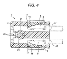
- each of the terminal receiving chambers 5 in the connector housing 2 is integrally formed with a flexible lance 20 for retaining the terminal.
- a projection 21 formed on an upper surface of the lance 20 enters in a retaining hole (not shown) formed in a bottom surface of the terminal 17 and retains the terminal 17 (primary retainment) .
- the rear holders 3, 4 are positioned at a backward end of their moving extent.
- the terminal retaining projections 16 are located at positions where they do not enter in the terminal receiving chambers 5.
- the rear holders 3, 4 are moved toward the forward end of the connector housing 2, the rear holders 3, 4 are drawn near to the connector housing 2 and the terminal retaining projections 16 enter in the terminal receiving chambers 5 through the terminal retaining holes 7.
- the terminal retaining projections 16 restrict the movement of the terminals 17 in a direction away from the terminal receiving chambers 5. In this manner, the terminals 17 are doubly retained (secondary retainment). Because of the tapered surfaces 18, 18 respectively formed on the terminal retaining projections 16, the rear holders 3, 4 can move smoothly.
- the state when the rear holders 3, 4 are positioned at the backward end of the connector housing 2 is herein referred to as “the temporarily retained state", and the state when the rear holders 3, 4 are positioned at the forward end of the connector housing is herein referred to as “the completely retained state”.
- the connector 1 as described herein above is so designed that the connector housing 2 and the rear holders 3, 4 which are component members of the connector are molded in the same metal mold.
- the works until the real holders 3, 4 have been brought into the temporarily retained state are intended to be conducted in the above mentioned same metal mold.
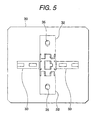
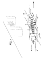
- Fig. 5 is a front view of a movable die of the metal mold for manufacturing the connector housing 2 and the rear holders 3, 4 of the connector 1.
- the metal mold includes a set of a movable die 30 which is shown in the drawing and a fixed die 31 to be located toward the front in the drawing.
- the movable die 30 includes housing molding dies (slide pins) 32, 32, which are slidable up and down and adapted to mold the connector housing 2 between them at their inner surfaces, and rear holder molding dies 33, 33 (assembly slide pins) which are slidable horizontally to the left and the right of the housing molding dies 32, 32. It is so constructed that a portion of the fixed die 31 is adapted to enter between the rear holder molding dies 33, 33 and side surfaces of the housing molding dies 32, 32, and the rear holders 3, 4 are intended to be molded between the fixed die 31 and the rear holder molding dies 33, 33.
- the movable die 30 holds the housing molding dies 32, 32 and the rear holder molding dies 33, 33 which are slide pins, it is apparent that the dies 32, 32, 33, 33 may be held in the fixed die 31.
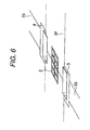
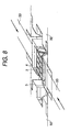
- Figs. 6 to 8 are schematic views showing movements of the slide pins in the movable die 30. It is to be noted that the drawings are only diagrammatic sketches but do not correspond to details in particular.
- These housing molding dies 32, 32 and the rear holder molding dies 33, 33 respectively slide so as to be drawn near to and apart from a core part at a center of the movable die 30.
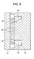
- the housing molding dies 32, 32 have diagonal through holes 35, 35 which are adapted to receive angular pins 34, 34 which are formed diagonally projecting from the fixed die 31 toward the movable die 30, as shown in Figs. 9 and 10.
- the housing molding dies 32, 32 are adapted to be drawn near to and apart from each other when the fixed die 31 and the movable die 30 are drawn near to and apart from each other on occasion of tightening and opening the metal mold.
- the connector housing 2 is molded between the housing molding dies 32, 32 at their inner surfaces, and as shown in Fig. 11, portions of the housing molding dies 32, 32 are extended as flat plates so as to form backward surfaces of the rear holders 3, 4. Therefore, when both the housing molding dies 32, 32 are kept closed, the rear holders 3, 4 are in contact with the housing molding dies 32, 32 from the backward. However, when the housing molding dies 32, 32 are opened, the rear holders 3, 4 are not in contact with the housing molding dies 32, 32 even at the backward side, as shown in Fig. 12. In other words, the rear holders 3, 4 are brought into a floating condition from the surrounding wall surfaces.
- a resetting drive rod 36 which projects from the fixed metal mold 31 and has an inclined surface at its distal end
- an engaging drive rod 37 which projects from an extruding pin (not shown) and has an inclined surface inclined in an opposite direction to the above mentioned resetting drive rod 36 are respectively slidable with respect to a cam portion 38 which is formed at each end of the rear holder molding dies 33, 33 and has inclined surfaces.
- the housing molding dies 32, 32 are close to each other in tight contact, and the rear holder molding dies 33, 33 wait at both sides of the housing molding dies 32, 32 at a position where spaces for the rear holders are formed.
- the fixed die 31 is tightly fitted to a front surface of the movable die 30 in such a manner that it projects into the terminal receiving chambers 5 and between the inner surfaces of the rear holders 3, 4. These projected portions are schematically illustrated by two-dotted chain lines in Fig. 7.
- the molten resin When molten resin is filled in the metal mold, the molten resin will be hardened between the fixed die 31 and the movable die 30 (See Fig. 6).
- the housing molding dies 32, 32 move apart from each other as shown in Figs. 7 and 10, as the angular pins 34 are removed from the through holes 35 of the housing molding dies 32, 32.
- the rear holders 3, 4 which have been in contact with the housing molding dies 32, 32 at the backward side will be detached from the housing molding dies 32, 32 and brought into a floating condition from the wall surface at the backward side, as shown in Figs. 11 and 12.
- the housing molding dies 32, 32 are moved apart due to sliding motion of the inclined angular pins 34 with respect to the through holes 35, and the connector housing 2 will be free at its four surfaces, namely upper, lower, left and right surfaces, and at its front surface.
- the inner surfaces of the rear holder 3 and the rear holder 4 which have been left in the rear holder molding dies 33, 33 are completely exposed, and the rear holders 3, 4 are opposed to each other and held on both sides of the connector housing 2 so as to clamp the connector housing 2.
- the extruding pin is actuated, and the inclined surface at the distal end of the engaging drive rod 37 slides along the inclined surface of the cam portion 38 of the rear holder molding die 33 thereby to move the rear holder molding die 33 toward the connector housing 2.
- the rear holders 3, 4 are pressed against the upper surface and the lower surface of the connector housing 2 from their U-shaped openings, while they are retained in the rear holder molding dies 33, 33, as shown in Fig. 8.
- the rear holders 3, 4 move in a non-contact manner, floating from the surrounding wall surfaces (See Fig. 12), when they move.
- the rear holders 3, 4 are conveyed to the connector housing 2 without generating cutting waste. Since there remains no trash such as cutting waste in the metal mold, molding accuracy of the rear holders 3, 4 which will be molded thereafter will be enhanced.
- the connector housing and the rear holders 3, 4 are simultaneously molded from resin, by the movable die 30 including the housing molding dies 32, 32 and the rear holder molding dies 33, 33 which are slidable, and the fixed die 31 to be mated with the movable die 30.
- the spaces between the connector housing 2 and the rear holders 3, 4 which are assembled to each other when the housing molding dies 32, 32 are opened on occasion of opening the fixed die 31 and the movable die 30.
- the rear holders 3, 4 are pressed against the connector housing 2 while the rear holders 3, 4 are respectively held by the rear holder molding dies 33, 33 from both the left and the right sides, and thus, the connector housing 2 and the rear holders 3, 4 are assembled. Even though deformation has occurred in the rear holders 3, 4 during molding, the engagement between the connector housing 2 and the rear holders 3, 4 will be reliably performed by the tapered surfaces 11, 12, 18.
- the movements of the housing molding dies 32, 32 and the rear holder molding dies 33, 33 are effected by the structure which is mechanically linked to the movement of the fixed die 31 and the movable die 30 and the movement of the extruding pin, hydraulic or pneumatic drive or motor drive can be also employed.
- the spaces between the resin molded articles can be formed not only by the mold opening and the rectilinear movement of the slide pins but also by two dimensional or three dimensional drive. Further, the resin molded articles can be moved by cooperation of a plurality of slide pins.
Landscapes
- Connector Housings Or Holding Contact Members (AREA)
- Manufacturing Of Electrical Connectors (AREA)
Claims (1)
- Struktur zum Herstellen von Eingriff eines Verbindergehäuses (2) und eines hinteren Halters (3, 4) miteinander, die in ein und derselben Metallform so geformt und zusammengesetzt werden, dass sie miteinander in Eingriff kommen, wobei die Struktur umfasst:wobei ein hinterer Endabschnitt des Verbindergehäuses als ein Abschnitt zum Positionieren des hinteren Halters in Bezug auf das Verbindergehäuse dient; gekennzeichnet durch:ein Verbindergehäuse, das eine Anschluss-Aufnahmekammer (5), in die ein Anschluss eingeführt werden kann, und ein Anschluss-Halteloch (7) enthält, das mit der Anschluss-Aufnahmekammer in Verbindung steht;einen hinteren Halter, der an dem Verbindergehäuse angebracht werden kann, wobei der hintere Halter so mit Harz geformt und in eine in Schnittansicht im Wesentlichen U-artige Form gebracht ist, dass er mit einem etwas kleiner bemessenen Teil des Verbindergehäuses in Eingriff ist;einen Anschluss-Haltevorsprung (16), der an dem hinteren Halter ausgebildet ist und eine Aussparung aufweist und der so eingerichtet ist, dass er in das Anschluss-Halteloch eintritt, um den Anschluss in der Anschluss-Aufnahmekammer zu halten;ein Paar Führungsschienen (8), die an dem Verbindergehäuse ausgebildet sind und mit denen der hintere Halter vorübergehend an dem Verbindergehäuse gehalten wird;ein Paar Vorsprünge (9), die an dem Verbindergehäuse ausgebildet sind und mit denen der hintere Halter vollständig an dem Verbindergehäuse gehalten wird;ein Paar Flügel (13), das an dem hinteren Halter ausgebildet ist und Führungsnuten aufweist, mit denen die Führungsschienen und die Vorsprünge jeweils in Eingriff gebracht werden,eine Vielzahl abgeschrägter Flächen (11, 12, 15, 18), die jeweils an den Führungsschienen am hinteren Endabschnitt und an vorderen Enden der Flügel ausgebildet sind, undeine abgeschrägte Fläche, die an dem Anschluss-Haltevorsprung ausgebildet ist.
Applications Claiming Priority (2)
| Application Number | Priority Date | Filing Date | Title |
|---|---|---|---|
| JP2000181399 | 2000-06-16 | ||
| JP2000181399A JP2001357955A (ja) | 2000-06-16 | 2000-06-16 | 同一成形金型内においてのハウジングとリアホルダとの係合構造 |
Publications (3)
| Publication Number | Publication Date |
|---|---|
| EP1164663A2 EP1164663A2 (de) | 2001-12-19 |
| EP1164663A3 EP1164663A3 (de) | 2002-09-25 |
| EP1164663B1 true EP1164663B1 (de) | 2004-08-04 |
Family
ID=18682337
Family Applications (1)
| Application Number | Title | Priority Date | Filing Date |
|---|---|---|---|
| EP01304827A Expired - Lifetime EP1164663B1 (de) | 2000-06-16 | 2001-05-31 | Befestigungstruktur eines Verbindergehäuses und einer von hinten angebrachten Kontakthalterung |
Country Status (4)
| Country | Link |
|---|---|
| US (1) | US6595807B2 (de) |
| EP (1) | EP1164663B1 (de) |
| JP (1) | JP2001357955A (de) |
| DE (1) | DE60104602T2 (de) |
Families Citing this family (9)
| Publication number | Priority date | Publication date | Assignee | Title |
|---|---|---|---|---|
| JP3674831B2 (ja) * | 1999-12-20 | 2005-07-27 | 矢崎総業株式会社 | リアホルダ付きコネクタの製造方法及び製造装置 |
| JP3415137B1 (ja) * | 2002-06-24 | 2003-06-09 | 住友電装株式会社 | コネクタ |
| JP2005183273A (ja) * | 2003-12-22 | 2005-07-07 | Japan Aviation Electronics Industry Ltd | コネクタのコンタクト保持構造 |
| US8951066B2 (en) | 2011-07-22 | 2015-02-10 | Lear Corporation | Electrical connector |
| US8721374B2 (en) * | 2011-07-22 | 2014-05-13 | Lear Corporation | Electrical connector |
| JP2013038044A (ja) * | 2011-08-11 | 2013-02-21 | Sumitomo Wiring Syst Ltd | コネクタ |
| DE102012209298B4 (de) * | 2012-06-01 | 2017-10-05 | Te Connectivity Germany Gmbh | Elektrischer Steckverbinder, Steckverbinderanordnung sowie Verfahren zum Montieren des Steckverbinders |
| JP6475669B2 (ja) * | 2016-07-13 | 2019-02-27 | 矢崎総業株式会社 | コネクタ |
| US10193276B1 (en) * | 2018-04-25 | 2019-01-29 | Sumitomo Wiring Systems, Ltd. | Connector housing assembly with coupling structures |
Family Cites Families (6)
| Publication number | Priority date | Publication date | Assignee | Title |
|---|---|---|---|---|
| JP2581477Y2 (ja) * | 1993-05-07 | 1998-09-21 | 住友電装株式会社 | コネクタ |
| JP3000869B2 (ja) * | 1994-11-07 | 2000-01-17 | 住友電装株式会社 | コネクタ |
| US5814356A (en) * | 1995-03-10 | 1998-09-29 | Sumitomo Wiring Systems, Ltd. | Manufacturing metal mold for assembling a resin molded assembly |
| JP3147752B2 (ja) | 1995-04-13 | 2001-03-19 | 住友電装株式会社 | コネクタの製造金型および製造方法 |
| JP2937074B2 (ja) * | 1995-04-18 | 1999-08-23 | 住友電装株式会社 | 二重係止コネクタ |
| JP3301329B2 (ja) * | 1996-12-27 | 2002-07-15 | 住友電装株式会社 | コネクタ |
-
2000
- 2000-06-16 JP JP2000181399A patent/JP2001357955A/ja active Pending
-
2001
- 2001-05-31 DE DE60104602T patent/DE60104602T2/de not_active Expired - Lifetime
- 2001-05-31 EP EP01304827A patent/EP1164663B1/de not_active Expired - Lifetime
- 2001-06-15 US US09/880,911 patent/US6595807B2/en not_active Expired - Lifetime
Also Published As
| Publication number | Publication date |
|---|---|
| DE60104602D1 (de) | 2004-09-09 |
| EP1164663A3 (de) | 2002-09-25 |
| US20010053638A1 (en) | 2001-12-20 |
| DE60104602T2 (de) | 2005-01-05 |
| US6595807B2 (en) | 2003-07-22 |
| JP2001357955A (ja) | 2001-12-26 |
| EP1164663A2 (de) | 2001-12-19 |
Similar Documents
| Publication | Publication Date | Title |
|---|---|---|
| EP0740366B1 (de) | Verbinder, dessen Herstellungsverfahren, Vorrichtung zum Formen eines derartigen Verbinders und Verfahren zum Montieren von einer Haltevorrichtung | |
| EP1164663B1 (de) | Befestigungstruktur eines Verbindergehäuses und einer von hinten angebrachten Kontakthalterung | |
| US6699420B2 (en) | Method of manufacturing a connector having rear holders | |
| EP0732772B1 (de) | Verbinderanordnung mit einer Verriegelungsvorrichtung, ein Verfahren zur Herstellung derselben und eine Giessform dafür | |
| JP3266782B2 (ja) | リヤホルダー付きコネクタの製造方法 | |
| EP1079469B1 (de) | Von hinten angebrachte Kontakthalterung für Verbinder und dessen Herstellungsverfahren | |
| JP3079952B2 (ja) | 樹脂成形組立品の製造方法 | |
| JP3079951B2 (ja) | 樹脂成形組立品の製造金型 | |
| JP3147753B2 (ja) | 樹脂成形組立品の製造金型および製造方法 | |
| JP3147752B2 (ja) | コネクタの製造金型および製造方法 | |
| JP3147755B2 (ja) | コネクタの製造金型および製造方法 | |
| JP3000883B2 (ja) | コネクタ | |
| JP3225783B2 (ja) | コネクタの製造方法 | |
| JP3175564B2 (ja) | コネクタの製造金型および製造方法 | |
| JP3860142B2 (ja) | コネクタ | |
| JP3013739B2 (ja) | コネクタ | |
| JP3175565B2 (ja) | コネクタの製造金型および製造方法 | |
| JP3147751B2 (ja) | コネクタの製造金型および製造方法 | |
| JP2000182709A (ja) | リテーナ付きコネクタ | |
| JPH09102350A (ja) | コネクタ、その製造方法、その製造用金型およびリテーナの装着方法 |
Legal Events
| Date | Code | Title | Description |
|---|---|---|---|
| PUAI | Public reference made under article 153(3) epc to a published international application that has entered the european phase |
Free format text: ORIGINAL CODE: 0009012 |
|
| AK | Designated contracting states |
Kind code of ref document: A2 Designated state(s): AT BE CH CY DE DK ES FI FR GB GR IE IT LI LU MC NL PT SE TR |
|
| AX | Request for extension of the european patent |
Free format text: AL;LT;LV;MK;RO;SI |
|
| PUAL | Search report despatched |
Free format text: ORIGINAL CODE: 0009013 |
|
| AK | Designated contracting states |
Kind code of ref document: A3 Designated state(s): AT BE CH CY DE DK ES FI FR GB GR IE IT LI LU MC NL PT SE TR |
|
| AX | Request for extension of the european patent |
Free format text: AL;LT;LV;MK;RO;SI |
|
| 17P | Request for examination filed |
Effective date: 20030318 |
|
| AKX | Designation fees paid |
Designated state(s): DE FR GB |
|
| 17Q | First examination report despatched |
Effective date: 20030515 |
|
| GRAP | Despatch of communication of intention to grant a patent |
Free format text: ORIGINAL CODE: EPIDOSNIGR1 |
|
| GRAS | Grant fee paid |
Free format text: ORIGINAL CODE: EPIDOSNIGR3 |
|
| GRAA | (expected) grant |
Free format text: ORIGINAL CODE: 0009210 |
|
| AK | Designated contracting states |
Kind code of ref document: B1 Designated state(s): DE FR GB |
|
| REG | Reference to a national code |
Ref country code: GB Ref legal event code: FG4D |
|
| REG | Reference to a national code |
Ref country code: IE Ref legal event code: FG4D |
|
| REF | Corresponds to: |
Ref document number: 60104602 Country of ref document: DE Date of ref document: 20040909 Kind code of ref document: P |
|
| ET | Fr: translation filed | ||
| PLBE | No opposition filed within time limit |
Free format text: ORIGINAL CODE: 0009261 |
|
| STAA | Information on the status of an ep patent application or granted ep patent |
Free format text: STATUS: NO OPPOSITION FILED WITHIN TIME LIMIT |
|
| 26N | No opposition filed |
Effective date: 20050506 |
|
| REG | Reference to a national code |
Ref country code: FR Ref legal event code: PLFP Year of fee payment: 16 |
|
| REG | Reference to a national code |
Ref country code: FR Ref legal event code: PLFP Year of fee payment: 17 |
|
| REG | Reference to a national code |
Ref country code: FR Ref legal event code: PLFP Year of fee payment: 18 |
|
| PGFP | Annual fee paid to national office [announced via postgrant information from national office to epo] |
Ref country code: DE Payment date: 20200519 Year of fee payment: 20 Ref country code: FR Payment date: 20200414 Year of fee payment: 20 |
|
| PGFP | Annual fee paid to national office [announced via postgrant information from national office to epo] |
Ref country code: GB Payment date: 20200520 Year of fee payment: 20 |
|
| REG | Reference to a national code |
Ref country code: DE Ref legal event code: R071 Ref document number: 60104602 Country of ref document: DE |
|
| REG | Reference to a national code |
Ref country code: GB Ref legal event code: PE20 Expiry date: 20210530 |
|
| PG25 | Lapsed in a contracting state [announced via postgrant information from national office to epo] |
Ref country code: GB Free format text: LAPSE BECAUSE OF EXPIRATION OF PROTECTION Effective date: 20210530 |