EP1164682A2 - Appareil de charge/décharge d'une batterie et procédé de charge/décharge d'une batterie - Google Patents
Appareil de charge/décharge d'une batterie et procédé de charge/décharge d'une batterie Download PDFInfo
- Publication number
- EP1164682A2 EP1164682A2 EP01305141A EP01305141A EP1164682A2 EP 1164682 A2 EP1164682 A2 EP 1164682A2 EP 01305141 A EP01305141 A EP 01305141A EP 01305141 A EP01305141 A EP 01305141A EP 1164682 A2 EP1164682 A2 EP 1164682A2
- Authority
- EP
- European Patent Office
- Prior art keywords
- battery
- remaining capacity
- capacity value
- microcomputer
- value
- Prior art date
- Legal status (The legal status is an assumption and is not a legal conclusion. Google has not performed a legal analysis and makes no representation as to the accuracy of the status listed.)
- Withdrawn
Links
Images



Classifications
-
- H—ELECTRICITY
- H01—ELECTRIC ELEMENTS
- H01M—PROCESSES OR MEANS, e.g. BATTERIES, FOR THE DIRECT CONVERSION OF CHEMICAL ENERGY INTO ELECTRICAL ENERGY
- H01M10/00—Secondary cells; Manufacture thereof
- H01M10/42—Methods or arrangements for servicing or maintenance of secondary cells or secondary half-cells
- H01M10/48—Accumulators combined with arrangements for measuring, testing or indicating the condition of cells, e.g. the level or density of the electrolyte
-
- G—PHYSICS
- G01—MEASURING; TESTING
- G01R—MEASURING ELECTRIC VARIABLES; MEASURING MAGNETIC VARIABLES
- G01R31/00—Arrangements for testing electric properties; Arrangements for locating electric faults; Arrangements for electrical testing characterised by what is being tested not provided for elsewhere
- G01R31/36—Arrangements for testing, measuring or monitoring the electrical condition of accumulators or electric batteries, e.g. capacity or state of charge [SoC]
- G01R31/3644—Constructional arrangements
- G01R31/3648—Constructional arrangements comprising digital calculation means, e.g. for performing an algorithm
-
- H—ELECTRICITY
- H01—ELECTRIC ELEMENTS
- H01M—PROCESSES OR MEANS, e.g. BATTERIES, FOR THE DIRECT CONVERSION OF CHEMICAL ENERGY INTO ELECTRICAL ENERGY
- H01M10/00—Secondary cells; Manufacture thereof
- H01M10/42—Methods or arrangements for servicing or maintenance of secondary cells or secondary half-cells
- H01M10/44—Methods for charging or discharging
-
- H—ELECTRICITY
- H02—GENERATION; CONVERSION OR DISTRIBUTION OF ELECTRIC POWER
- H02J—ELECTRIC POWER NETWORKS; CIRCUIT ARRANGEMENTS OR SYSTEMS FOR SUPPLYING OR DISTRIBUTING ELECTRIC POWER; SYSTEMS FOR STORING ELECTRIC ENERGY
- H02J7/00—Circuit arrangements for charging or discharging batteries or for supplying loads from batteries
- H02J7/80—Circuit arrangements for charging or discharging batteries or for supplying loads from batteries including monitoring or indicating arrangements
- H02J7/82—Control of state of charge [SOC]
-
- H—ELECTRICITY
- H02—GENERATION; CONVERSION OR DISTRIBUTION OF ELECTRIC POWER
- H02J—ELECTRIC POWER NETWORKS; CIRCUIT ARRANGEMENTS OR SYSTEMS FOR SUPPLYING OR DISTRIBUTING ELECTRIC POWER; SYSTEMS FOR STORING ELECTRIC ENERGY
- H02J7/00—Circuit arrangements for charging or discharging batteries or for supplying loads from batteries
- H02J7/90—Regulation of charging or discharging current or voltage
- H02J7/933—Regulation of charging or discharging current or voltage the cycle being controlled or terminated in response to electric parameters
-
- G—PHYSICS
- G01—MEASURING; TESTING
- G01R—MEASURING ELECTRIC VARIABLES; MEASURING MAGNETIC VARIABLES
- G01R31/00—Arrangements for testing electric properties; Arrangements for locating electric faults; Arrangements for electrical testing characterised by what is being tested not provided for elsewhere
- G01R31/36—Arrangements for testing, measuring or monitoring the electrical condition of accumulators or electric batteries, e.g. capacity or state of charge [SoC]
- G01R31/382—Arrangements for monitoring battery or accumulator variables, e.g. SoC
- G01R31/3842—Arrangements for monitoring battery or accumulator variables, e.g. SoC combining voltage and current measurements
-
- Y—GENERAL TAGGING OF NEW TECHNOLOGICAL DEVELOPMENTS; GENERAL TAGGING OF CROSS-SECTIONAL TECHNOLOGIES SPANNING OVER SEVERAL SECTIONS OF THE IPC; TECHNICAL SUBJECTS COVERED BY FORMER USPC CROSS-REFERENCE ART COLLECTIONS [XRACs] AND DIGESTS
- Y02—TECHNOLOGIES OR APPLICATIONS FOR MITIGATION OR ADAPTATION AGAINST CLIMATE CHANGE
- Y02E—REDUCTION OF GREENHOUSE GAS [GHG] EMISSIONS, RELATED TO ENERGY GENERATION, TRANSMISSION OR DISTRIBUTION
- Y02E60/00—Enabling technologies; Technologies with a potential or indirect contribution to GHG emissions mitigation
- Y02E60/10—Energy storage using batteries
Definitions
- the present invention generally relates to a charging/discharging apparatus, and particularly to a battery charging/discharging apparatus and a battery charging/discharging method in which the remaining capacity of a battery can be determined with high accuracy.
- Fig. 1 of the accompanying drawings is a block diagram showing an example structure of a conventional battery pack 1.
- the battery pack 1 includes cells 12-1 and 12-2 connected in series (hereinafter collectively referred to as "battery 12", unless the cells 12-1 and 12-2 should be discriminated), which may comprise lithium ion batteries, for powering electronic devices.
- the positive electrode of the cell 12-1 is connected to a battery terminal 11-1 while the negative electrode of the cell 12-2 is connected to a battery terminal 11-2 via a resistor 13 provided for current detection and a protection device 14.
- the battery terminals 11-1 and 11-2 are connected to connection terminals of the electronic device so that the electronic device can be powered by the battery 12.
- a cell voltage detector 15 detects a cell voltage when the cell 12-1 and the cell 12-2 are connected in series, and outputs the detection result to a microcomputer 17.
- a charging/discharging current detector 16 detects the direction and value of voltage drop due to the current flowing to the resistor 13 in order to detect the existence of a charging current or a discharging current. The result is then output to the microcomputer 17.
- the protection device 14 protects the battery 12 from being overcharged or overdischarged.
- the microcomputer 17 calculates the remaining battery capacity value based on the cell voltage supplied from the cell voltage detector 15, and stores the resulting value in an internal memory 17a.
- the microcomputer 17 switches to wake-up mode if a charging current or a discharging current is supplied from the charging/discharging current detector 16 or if it receives incoming data from the outside. If no charging/discharging current is supplied within a predetermined time or if no incoming data is received while it is in wake-up mode, the microcomputer 17 switches to sleep mode.
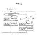
- Fig. 2 is a flowchart of the process for calculating the remaining battery capacity value of the battery pack 1 shown in Fig. 1.
- step S3 the microcomputer 17 stores the up-to-date remaining capacity value calculated by equation (2) in the memory 17a or updates the existing remaining capacity value, and the process returns to step S1 to iterate the above-described operation.
- step S1 If it is determined at step S1 that the battery 12 has not been charged, the process proceeds to step S4, in which the microcomputer 17 further determines whether or not the battery 12 has been discharged, i.e., whether or not a discharging current has been supplied from the charging/discharging current detector 16. If it is determined at step S4 that it has not been discharged, the process returns to step S1 to iterate the above-described operation.
- step S6 the microcomputer 17 stores the up-to-date remaining capacity value calculated by equation (4) in the memory 17a or updates the existing remaining capacity value, and the process returns to step S1 to iterate the above-described operation.
- the calculation process using a charging current or a discharging current is performed to determine the remaining battery capacity.
- the microcomputer 17 utilizes the power supplied from the battery 12 in order to determine the remaining battery capacity. Hence, when the battery is in standby mode (when the remaining battery capacity calculation process is not performed), the microcomputer 17 switches to sleep mode in order to reduce the power consumption of the microcomputer 17. This may suppress discharge current (leakage current) of the battery 12 in standby mode.
- the microcomputer 17 When the charging/discharging current detector 16 detects a charging current or a discharging current, the microcomputer 17 switches to wake-up mode; however, discharge current (leakage current) when the battery is in standby mode is minute, and thus cannot be detected by the charging/discharging current detector 16.
- the microcomputer 17 If the microcomputer 17 is forced not to enter sleep mode and is allowed to detect the standby current, the current will be minute, and will not be able to be precisely detected. There still exists such a problem that an error occurs between the remaining capacity value stored in the memory 17a and the actual capacity value.
- a battery charging/discharging apparatus for determining the remaining capacity of a battery includes a measuring unit for measuring a standby time of the battery, a correction value calculating unit for calculating a correction value for the remaining capacity of the battery based on the standby time measured by the measuring unit, and a correcting unit for correcting a current remaining capacity value of the battery based on the correction value calculated by the correction value calculating unit.
- the battery charging/discharging apparatus may further include a determining unit for determining whether or not the standby time has reached a predetermined time.
- the correction value calculating unit may calculate the correction value for the remaining capacity of the battery at a predetermined time interval based on the result of the determining unit.
- a battery charging/discharging method for determining the remaining capacity of a battery includes the steps of measuring a standby time of the battery, calculating a correction value for the remaining capacity of the battery based on the standby time measured in the measuring step, and correcting a current remaining capacity value of the battery based on the correction value calculated in the calculating step.
- the correction value is calculated based on the standby time of the battery, and is used to correct currently stored remaining capacity value of the battery. This enables the remaining battery capacity to be determined with high accuracy.
- the battery charging/discharging apparatus may further include a setting unit for setting the appropriate remaining capacity value that is suitable for the cell voltage.
- a battery charging/discharging method for determining the remaining capacity of a battery includes the steps of detecting a cell voltage, reading an appropriate remaining capacity value based on the cell voltage detected in the detecting step, comparing the appropriate remaining capacity value read in the reading step with a currently stored remaining capacity value, and updating the currently stored remaining capacity value based on the result in the comparing step.
- an appropriate remaining capacity value is read.
- the read remaining capacity value is then compared with a currently stored remaining capacity value to update the currently stored remaining capacity value based on the comparing result. This enables the remaining battery capacity to be determined at low cost with ease.
- Fig. 3 is a block diagram of a battery pack 1 according to one embodiment of the present invention.
- the same reference numerals are assigned to the parts corresponding to those in the conventional one shown in Fig. 1, and a description thereof is thus omitted as appropriate.
- the battery pack 1 includes cell voltage detectors 15-1 and 15-2 coupled to the cells 12-1 and 12-2, respectively, to detect cell voltages with higher accuracy, and further includes a timer 21.
- Other parts are constructed in the same manner as those in the conventional one shown in Fig. 1.
- the cell voltage detector 15-1 detects the cell voltage of the cell 12-1, and outputs the detection result to the microcomputer 17.
- the cell voltage detector 15-2 detects the cell voltage of the cell 12-2, and outputs the detection result to the microcomputer 17.
- the microcomputer 17 calculates the remaining battery capacity value based on the cell voltages supplied from the cell voltage detectors 15-1 and 15-2, and stores the resulting value in the internal memory 17a.
- the microcomputer 17 switches to sleep mode. Then, the microcomputer 17 controls the timer 21 so as to start measuring the standby time. If a charging current or a discharging current is detected, the microcomputer 17 switches to wake-up mode. Then, the microcomputer 17 controls the timer 21 so as to stop measuring the standby time, and reads the measured standby time. Based on the standby time read, the microcomputer 17 calculates the correction value using a calculation process, as will be described, to correct the remaining battery capacity value.
- the timer 21 In response to the instruction from the microcomputer 17, the timer 21 starts measuring the standby time. The timer 21 also stops measuring the standby time in response to the instruction of the microcomputer 17.
- Fig. 4 is a flowchart of the process which is performed by the microcomputer 17 for correcting the remaining battery capacity value of the battery pack 1 shown in Fig. 3.
- the microcomputer 17 determines whether or not the battery 12 has been discharged or charged, i.e., whether or not a discharging current or a charging current has been detected by the charging/discharging current detector 16 within a predetermined time, e.g., 10 seconds. If it is determined at step S11 that the battery 12 has not been discharged or charged within the predetermined time, the process proceeds to step S12.
- the microcomputer 17 controls the timer 21 so as to start measuring the standby time, before switching to sleep mode.
- the microcomputer 17 determines whether or not the battery 12 has been discharged or charged, i.e., whether or not a discharging current or a charging current has been detected by the charging/discharging current detector 16. If it is determined at step S14 that the battery 12 has not been discharged or charged, the process returns to step S13, in which the microcomputer 17 waits while it remains in sleep mode. If it is determined at step S14 that the battery 12 has been discharged or charged, the process proceeds to step S15.
- step S14 the microcomputer 17 switches to wake-up mode at step S15.
- steps S16 and S17 the microcomputer 17 controls the timer 21 so as to stop measuring the standby time, and reads the measured standby time. The microcomputer 17 then resets the timer 21.
- step S19 the microcomputer 17 reads the remaining capacity value stored in the memory 17a, and calculates the up-to-date remaining capacity value by equation (6) as follows.
- up-to-date remaining capacity value remaining capacity value read from the memory 17a - correction value
- step S19 the microcomputer 17 stores the up-to-date remaining capacity value calculated by equation (6) in the memory 17a or updates the existing remaining capacity value, and the process returns to step S11 to iterate the above-described operation.
- the standby current, the battery self-discharge current, and the standby time are used to calculate the correction value in this way, and the remaining battery capacity can therefore be corrected with high accuracy.
- the correction process is performed at fixed time intervals while the microcomputer 17 is in wake-up mode, thus the remaining battery capacity value can be more accurately corrected.
- Fig. 5 is a flowchart of the process for correcting the remaining battery capacity value according to a modification of the embodiment of the present invention, in which the remaining battery capacity value is corrected at a fixed time interval.
- step S31 the microcomputer 17 determines whether or not the battery 12 has been discharged or charged within a predetermined time. If it is determined at step S31 that it has not been discharged or charged within the predetermined time, the process proceeds to step S32.
- the microcomputer 17 controls the timer 21 so as to start measuring the standby time, before switching to sleep mode.
- the microcomputer 17 determines whether or not a preset time has elapsed. The period in which an overflow does not occur is set in advance as the preset time, and when the preset time has elapsed, the timer 21 notifies the microcomputer 17 of the elapse of the preset time. That is, the microcomputer 17 determines whether or not it receives a command from the timer 21 indicating that the preset time has elapsed.
- step S34 If it is determined at step S34 that the preset time has elapsed, the process proceeds to step S35, in which the microcomputer 17 switches to wake-up mode in response to the command from the timer 21.
- step S36 the microcomputer 17 resets the timer 21.
- the microcomputer 17 calculates the correction value from equation (5), and further calculates the up-to-date remaining capacity value from equation (6). Then, the microcomputer 17 stores the up-to-date remaining capacity value in the memory 17a or updates the existing remaining capacity value, and the process returns to step S31 to iterate the above-described operation.
- step S31 If it is determined at step S31 that the battery 12 has been discharged or charged within the predetermined time, or if it is determined at step S14 that the preset time has not elapsed, the process proceeds to step S39.
- steps S39 to S44 is the same as that of steps S14 to S19 as previously described with reference to Fig. 4, and a description thereof is thus omitted.
- the standby current, the battery self-discharge current, and the standby time are used to calculate the correction value at fixed time intervals, thus the remaining battery capacity may be corrected with high accuracy even when the battery pack 1 is in standby mode for a long time.
- the timer 21 is used to measure the standby time, and the remaining battery capacity value is corrected based on the resulting standby time. Instead, cell voltages may be detected to correct the remaining battery capacity value at low cost with ease although the correction accuracy is not higher than that when an additional timer is provided.
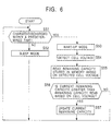
- Fig. 6 is a flowchart of the process for correcting the remaining battery capacity value according to another modification of the embodiment of the present invention, in which the remaining battery capacity value is corrected based on cell voltages.
- step S51 the microcomputer 17 determines whether or not the battery 12 has been discharged or charged within a predetermined time. If it is determined at step S51 that it has not been discharged or charged within the predetermined time, the process proceeds to step S52, in which the microcomputer 17 switches to sleep mode.
- step S51 If it is determined at step S51 that the battery 12 has been discharged or charged, the process proceeds to step S53, in which the microcomputer 17 switches to wake-up mode.
- step S54 the microcomputer 17 detects the cell voltages supplied by the cell voltage detectors 15-1 and 15-2.
- the microcomputer 17 reads appropriate remaining capacity value from the memory 17a based on the cell voltages detected at step S54.
- the remaining battery capacity value suitable for each cell voltage is set and is stored in the memory 17a.
- the microcomputer 17 reads the current remaining capacity value stored in the memory 17a, and determines whether or not it is greater than the remaining capacity value which is read based on the cell voltages at step S55.
- step S56 If it is determined at step S56 that the current remaining capacity value stored in the memory 17a is greater than the remaining capacity value which is read based on the cell voltages, the process proceeds step S57, in which the microcomputer 17 stores the remaining capacity value which is read based on the cell voltages as the current remaining capacity value in the memory 17a or updates the current remaining capacity value. Then, the process returns to step S51 to iterate the above-described operation.
- step S56 If it is determined at step S56 that the current remaining capacity value stored in the memory 17a is not greater than, i.e., equal to, the remaining capacity value which is read based on the cell voltages, the process skips step S57 (without updating the current remaining capacity value) back to step S51 to iterate the above-described operation.
- the current remaining capacity value is updated with the remaining capacity value which is read based on the cell voltages. This allows significant deviations of the remaining capacity value to be corrected even when no timer is used.
Landscapes
- Engineering & Computer Science (AREA)
- Manufacturing & Machinery (AREA)
- Chemical & Material Sciences (AREA)
- Chemical Kinetics & Catalysis (AREA)
- Electrochemistry (AREA)
- General Chemical & Material Sciences (AREA)
- Power Engineering (AREA)
- Physics & Mathematics (AREA)
- General Physics & Mathematics (AREA)
- Charge And Discharge Circuits For Batteries Or The Like (AREA)
- Secondary Cells (AREA)
- Tests Of Electric Status Of Batteries (AREA)
Priority Applications (1)
| Application Number | Priority Date | Filing Date | Title |
|---|---|---|---|
| EP06021192A EP1758227A3 (fr) | 2000-06-16 | 2001-06-13 | Appareil de charge/décharge d'une batterie et procédé de charge/décharge d'une batterie |
Applications Claiming Priority (2)
| Application Number | Priority Date | Filing Date | Title |
|---|---|---|---|
| JP2000180675A JP4642185B2 (ja) | 2000-06-16 | 2000-06-16 | バッテリーパック |
| JP2000180675 | 2000-06-16 |
Related Child Applications (1)
| Application Number | Title | Priority Date | Filing Date |
|---|---|---|---|
| EP06021192A Division EP1758227A3 (fr) | 2000-06-16 | 2001-06-13 | Appareil de charge/décharge d'une batterie et procédé de charge/décharge d'une batterie |
Publications (2)
| Publication Number | Publication Date |
|---|---|
| EP1164682A2 true EP1164682A2 (fr) | 2001-12-19 |
| EP1164682A3 EP1164682A3 (fr) | 2005-08-10 |
Family
ID=18681709
Family Applications (2)
| Application Number | Title | Priority Date | Filing Date |
|---|---|---|---|
| EP01305141A Withdrawn EP1164682A3 (fr) | 2000-06-16 | 2001-06-13 | Appareil de charge/décharge d'une batterie et procédé de charge/décharge d'une batterie |
| EP06021192A Withdrawn EP1758227A3 (fr) | 2000-06-16 | 2001-06-13 | Appareil de charge/décharge d'une batterie et procédé de charge/décharge d'une batterie |
Family Applications After (1)
| Application Number | Title | Priority Date | Filing Date |
|---|---|---|---|
| EP06021192A Withdrawn EP1758227A3 (fr) | 2000-06-16 | 2001-06-13 | Appareil de charge/décharge d'une batterie et procédé de charge/décharge d'une batterie |
Country Status (6)
| Country | Link |
|---|---|
| US (2) | US20020021108A1 (fr) |
| EP (2) | EP1164682A3 (fr) |
| JP (1) | JP4642185B2 (fr) |
| KR (1) | KR100826953B1 (fr) |
| CN (1) | CN1225054C (fr) |
| HK (1) | HK1045603B (fr) |
Cited By (5)
| Publication number | Priority date | Publication date | Assignee | Title |
|---|---|---|---|---|
| EP1455194A1 (fr) * | 2003-03-03 | 2004-09-08 | Sony Ericsson Mobile Communications AB | Dispositif et procédé pour charger des éléments de batterie |
| FR2852158A1 (fr) * | 2003-03-04 | 2004-09-10 | Hawker Sa | Procede et installation de surveillance de l'etat et de gestion d'une batterie au plomb |
| WO2004079383A1 (fr) * | 2003-03-03 | 2004-09-16 | Sony Ericsson Mobile Communications Ab | Appareil et procedes pour charger des elements de batterie |
| FR2906371A1 (fr) * | 2006-09-21 | 2008-03-28 | Valeo Electronique Sys Liaison | Dispositif de mesure de parametres d'une source d'alimentation electrique, comprenant une horloge |
| CN108627773A (zh) * | 2018-05-04 | 2018-10-09 | 深圳市道通智能航空技术有限公司 | 电池功耗控制方法、装置及无人飞行器 |
Families Citing this family (39)
| Publication number | Priority date | Publication date | Assignee | Title |
|---|---|---|---|---|
| KR20030072027A (ko) * | 2002-03-05 | 2003-09-13 | 주식회사 레인콤 | 충전 및 방전 기능을 구비한 휴대용 전자 장치 |
| JP4157317B2 (ja) * | 2002-04-10 | 2008-10-01 | 株式会社日立製作所 | 状態検知装置及びこれを用いた各種装置 |
| KR100686826B1 (ko) * | 2005-09-20 | 2007-02-26 | 삼성에스디아이 주식회사 | 리튬 이온 전지 및 리튬 이온 전지의 장기 보존 방법 |
| US20090150101A1 (en) * | 2007-12-06 | 2009-06-11 | Mitsumi Electric Co., Ltd. | Semiconductor Integrated Circuit Device and Battery Pack |
| RU2465811C2 (ru) | 2007-12-10 | 2012-11-10 | БАЙЕР ХЕЛТКЭА ЭлЭлСи | Управление быстрым зарядом и питанием выполненного с батарейным питанием измерителя аналитов в текучей среде |
| KR101405565B1 (ko) * | 2008-08-29 | 2014-06-10 | 기아자동차주식회사 | 후드 스위치에 의한 차량 방전 개선 방법 |
| US20100102781A1 (en) * | 2008-10-24 | 2010-04-29 | Sony Ericsson Mobile Communications Ab | Apparatus and method for charging a battery |
| JP5369067B2 (ja) * | 2010-08-25 | 2013-12-18 | 三菱自動車工業株式会社 | 充電制御装置 |
| JP2012057998A (ja) * | 2010-09-07 | 2012-03-22 | Calsonic Kansei Corp | 二次電池の充電率算出装置および充電率算出方法 |
| JP2012070528A (ja) * | 2010-09-24 | 2012-04-05 | Nec Tokin Corp | 蓄電装置、およびその制御方法 |
| JP5527895B2 (ja) * | 2010-11-18 | 2014-06-25 | パナソニック株式会社 | 二次電池の制御装置および制御方法 |
| KR101211875B1 (ko) | 2011-03-11 | 2012-12-18 | 삼성에스디아이 주식회사 | 배터리 관리 시스템 및 그를 포함하는 배터리 팩 |
| EP2523305B1 (fr) * | 2011-05-12 | 2017-10-18 | Moog Unna GmbH | Dispositif d'alimentation d'urgence en énergie et procédé d'alimentation d'urgence en énergie |
| US9171793B2 (en) * | 2011-05-26 | 2015-10-27 | Hewlett-Packard Development Company, L.P. | Semiconductor device having a trace comprises a beveled edge |
| JP5847506B2 (ja) * | 2011-09-14 | 2016-01-20 | 株式会社ケーヒン | 電子制御装置及び車両制御システム |
| US9625529B2 (en) * | 2011-11-11 | 2017-04-18 | Stmicroelectronics, Inc. | Battery pack management |
| JP6065561B2 (ja) | 2012-03-08 | 2017-01-25 | 日産自動車株式会社 | 二次電池の制御装置およびsoc検出方法 |
| JP6135110B2 (ja) * | 2012-03-08 | 2017-05-31 | 日産自動車株式会社 | 二次電池の制御装置、充電制御方法およびsoc検出方法 |
| GB2502055A (en) | 2012-05-14 | 2013-11-20 | Nicoventures Holdings Ltd | Modular electronic smoking device |
| GB2507104A (en) | 2012-10-19 | 2014-04-23 | Nicoventures Holdings Ltd | Electronic inhalation device |
| GB2519101A (en) | 2013-10-09 | 2015-04-15 | Nicoventures Holdings Ltd | Electronic vapour provision system |
| JP6176487B2 (ja) * | 2013-12-20 | 2017-08-09 | トヨタ自動車株式会社 | 二次電池の製造方法 |
| US10886765B2 (en) | 2015-11-09 | 2021-01-05 | Johnson Industries, Inc. | Lighted connector for a battery cable |
| US9705351B2 (en) | 2015-11-09 | 2017-07-11 | Johnson Industries, Inc. | Battery exercising device |
| US10177589B2 (en) | 2015-11-09 | 2019-01-08 | Johnson Industries, Inc. | Battery exercising device |
| JP6220904B2 (ja) * | 2016-01-14 | 2017-10-25 | 本田技研工業株式会社 | 蓄電装置 |
| JP6769046B2 (ja) * | 2016-03-01 | 2020-10-14 | 株式会社Gsユアサ | 蓄電素子の監視装置、蓄電素子モジュール、socの推定方法 |
| CN107069846B (zh) * | 2017-03-09 | 2019-05-24 | 东莞博力威电池有限公司 | 校正电池的电压电流的方法及电池系统 |
| KR101914256B1 (ko) * | 2017-04-10 | 2018-11-01 | 주식회사 디알텍 | 방사선 디텍터 및 방사선 디텍터의 전원 관리방법 |
| KR102167429B1 (ko) | 2017-04-12 | 2020-10-19 | 주식회사 엘지화학 | 에너지 저장 장치의 과방전 방지 및 재기동 장치 및 방법 |
| CN108011415B (zh) * | 2017-11-28 | 2021-08-10 | 启攀微电子(上海)有限公司 | 一种集成电池保护的电源管理单元芯片 |
| TWI628453B (zh) * | 2018-01-19 | 2018-07-01 | 新盛力科技股份有限公司 | 電池容量的預估方法 |
| KR102424295B1 (ko) * | 2018-09-27 | 2022-07-21 | 주식회사 엘지에너지솔루션 | Soc 추정 장치 및 방법 |
| KR102232204B1 (ko) * | 2019-03-19 | 2021-03-25 | 주식회사 케이티앤지 | 에어로졸 생성장치 및 이의 배터리 수명 추정방법 |
| CN109756003A (zh) * | 2019-03-20 | 2019-05-14 | 泰顺永庆电力技术有限公司 | 锂电池充放电管理系统 |
| CN109861343A (zh) * | 2019-03-22 | 2019-06-07 | 张宇桐 | 一种间歇式电源管理电路 |
| KR102463898B1 (ko) * | 2020-11-11 | 2022-11-03 | 주식회사 케이티앤지 | 에어로졸 생성장치 및 그 동작방법 |
| WO2023004645A1 (fr) * | 2021-07-28 | 2023-02-02 | 宁德时代新能源科技股份有限公司 | Procédé et appareil de charge, véhicule et support de stockage lisible par ordinateur |
| CN119863225B (zh) * | 2023-10-19 | 2026-01-13 | 宁德时代新能源科技股份有限公司 | 测试资源管控方法、装置、设备、存储介质和程序产品 |
Citations (2)
| Publication number | Priority date | Publication date | Assignee | Title |
|---|---|---|---|---|
| JPS61209373A (ja) * | 1985-03-14 | 1986-09-17 | Matsushita Electric Works Ltd | 電池の残量認識回路 |
| JPH10164764A (ja) * | 1996-11-25 | 1998-06-19 | Yamaha Motor Co Ltd | 電池容量監視方法 |
Family Cites Families (19)
| Publication number | Priority date | Publication date | Assignee | Title |
|---|---|---|---|---|
| FR2478893A1 (fr) * | 1980-03-21 | 1981-09-25 | Cardiac Recorders Ltd | Perfectionnements a l'alimentation electrique des equipements a disponibilite permanente |
| US5032825A (en) * | 1990-03-02 | 1991-07-16 | Motorola, Inc. | Battery capacity indicator |
| JPH0641351U (ja) * | 1992-01-31 | 1994-05-31 | 株式会社日立製作所 | 携帯形端末装置用電池の充放電装置 |
| US5514946A (en) * | 1993-03-19 | 1996-05-07 | Compaq Computer Corp. | Battery pack including static memory and a timer for charge management |
| US5455499A (en) * | 1993-04-26 | 1995-10-03 | Motorola, Inc. | Method and apparatus for indicating a battery status |
| JP3454928B2 (ja) * | 1994-08-05 | 2003-10-06 | 株式会社日本自動車部品総合研究所 | バッテリの残存使用量判定装置 |
| JPH08136626A (ja) * | 1994-09-16 | 1996-05-31 | Seiko Epson Corp | バッテリー残存容量計及びバッテリー残存容量の演算方法 |
| US5606242A (en) * | 1994-10-04 | 1997-02-25 | Duracell, Inc. | Smart battery algorithm for reporting battery parameters to an external device |
| US5633573A (en) * | 1994-11-10 | 1997-05-27 | Duracell, Inc. | Battery pack having a processor controlled battery operating system |
| US5698983A (en) * | 1995-04-07 | 1997-12-16 | Yazaki Corporation | Method and apparatus for measuring and displaying remaining battery capacity as a two dimensional dot curve |
| JP3164999B2 (ja) * | 1995-04-07 | 2001-05-14 | 矢崎総業株式会社 | 電池残存容量測定方法及びその装置 |
| JPH09116977A (ja) * | 1995-10-16 | 1997-05-02 | Honda Motor Co Ltd | 表示用信号送受信方法 |
| US5761072A (en) * | 1995-11-08 | 1998-06-02 | Ford Global Technologies, Inc. | Battery state of charge sensing system |
| JP3251502B2 (ja) * | 1996-06-27 | 2002-01-28 | 矢崎総業株式会社 | 電気自動車の電池残存容量測定装置 |
| US5903764A (en) * | 1997-05-02 | 1999-05-11 | Micro International, Ltd. | Smart battery selector offering power conversion internally within a portable device |
| US6025695A (en) * | 1997-07-09 | 2000-02-15 | Friel; Daniel D. | Battery operating system |
| JPH11223665A (ja) * | 1998-02-04 | 1999-08-17 | Nissan Motor Co Ltd | 電池の残存容量演算装置 |
| US6828761B1 (en) * | 2000-06-16 | 2004-12-07 | Sony Corporation | Battery charging/discharging apparatus and battery charging/discharging method |
| JP6081425B2 (ja) * | 2014-09-19 | 2017-02-15 | 本田技研工業株式会社 | 車体構造 |
-
2000
- 2000-06-16 JP JP2000180675A patent/JP4642185B2/ja not_active Expired - Fee Related
-
2001
- 2001-06-13 EP EP01305141A patent/EP1164682A3/fr not_active Withdrawn
- 2001-06-13 EP EP06021192A patent/EP1758227A3/fr not_active Withdrawn
- 2001-06-14 KR KR1020010033504A patent/KR100826953B1/ko not_active Expired - Fee Related
- 2001-06-15 US US09/882,403 patent/US20020021108A1/en not_active Abandoned
- 2001-06-15 CN CNB011210338A patent/CN1225054C/zh not_active Expired - Fee Related
-
2002
- 2002-06-27 HK HK02104804.6A patent/HK1045603B/zh not_active IP Right Cessation
-
2005
- 2005-07-11 US US11/178,674 patent/US7071654B2/en not_active Expired - Lifetime
Patent Citations (2)
| Publication number | Priority date | Publication date | Assignee | Title |
|---|---|---|---|---|
| JPS61209373A (ja) * | 1985-03-14 | 1986-09-17 | Matsushita Electric Works Ltd | 電池の残量認識回路 |
| JPH10164764A (ja) * | 1996-11-25 | 1998-06-19 | Yamaha Motor Co Ltd | 電池容量監視方法 |
Cited By (7)
| Publication number | Priority date | Publication date | Assignee | Title |
|---|---|---|---|---|
| EP1455194A1 (fr) * | 2003-03-03 | 2004-09-08 | Sony Ericsson Mobile Communications AB | Dispositif et procédé pour charger des éléments de batterie |
| WO2004079383A1 (fr) * | 2003-03-03 | 2004-09-16 | Sony Ericsson Mobile Communications Ab | Appareil et procedes pour charger des elements de batterie |
| FR2852158A1 (fr) * | 2003-03-04 | 2004-09-10 | Hawker Sa | Procede et installation de surveillance de l'etat et de gestion d'une batterie au plomb |
| WO2004081585A3 (fr) * | 2003-03-04 | 2004-10-21 | Hawker S A | Procede et installation de surveillance de l'etat et de gestion d'une batterie au plomb |
| FR2906371A1 (fr) * | 2006-09-21 | 2008-03-28 | Valeo Electronique Sys Liaison | Dispositif de mesure de parametres d'une source d'alimentation electrique, comprenant une horloge |
| WO2008035004A3 (fr) * | 2006-09-21 | 2008-05-08 | Valeo Electronique Sys Liaison | Dispositif de mesure de parametres d'une source d'alimentation electrique, comprenant une horloge |
| CN108627773A (zh) * | 2018-05-04 | 2018-10-09 | 深圳市道通智能航空技术有限公司 | 电池功耗控制方法、装置及无人飞行器 |
Also Published As
| Publication number | Publication date |
|---|---|
| US7071654B2 (en) | 2006-07-04 |
| EP1758227A2 (fr) | 2007-02-28 |
| KR20010113491A (ko) | 2001-12-28 |
| EP1164682A3 (fr) | 2005-08-10 |
| HK1045603B (zh) | 2006-07-14 |
| CN1330427A (zh) | 2002-01-09 |
| EP1758227A3 (fr) | 2007-04-11 |
| JP4642185B2 (ja) | 2011-03-02 |
| KR100826953B1 (ko) | 2008-05-02 |
| HK1045603A1 (en) | 2002-11-29 |
| US20050242821A1 (en) | 2005-11-03 |
| US20020021108A1 (en) | 2002-02-21 |
| JP2002010503A (ja) | 2002-01-11 |
| CN1225054C (zh) | 2005-10-26 |
Similar Documents
| Publication | Publication Date | Title |
|---|---|---|
| US7071654B2 (en) | Battery charging/discharging apparatus and battery charging/discharging method | |
| KR101166099B1 (ko) | 2차 전지의 충전 방법, 2차 전지의 잔여용량율 산출 방법 및 전지 팩 | |
| EP0600234B1 (fr) | Système d'affichage de la capacité résiduelle d'une batterie | |
| EP1167988B1 (fr) | Boîtier à piles rechargeables | |
| JP3454657B2 (ja) | 二次電池の残存容量検出方法 | |
| EP1049231A1 (fr) | Méthode de mesure de paramètres, méthode et appareil de commande de charge et de décharge et méthode de prédiction de durée de vie pour batteries secondaires et appareil d' accumulation d'énergie les utilisant | |
| US6930465B2 (en) | Residual capacity correction method for battery | |
| US5723971A (en) | Apparatus for charging a battery for a charge time determined based on the depth of discharge | |
| EP1754978A2 (fr) | Appareil, méthode et programme d'ordinateur d'estimation de la capacité résiduelle d'une batterie, | |
| JPH11329512A (ja) | 二次電池の容量劣化判断方法およびその判断装置 | |
| CN100382408C (zh) | 蓄电池充电方法、蓄电池剩余容量比率计算方法及电池组 | |
| US6828761B1 (en) | Battery charging/discharging apparatus and battery charging/discharging method | |
| US7911531B2 (en) | Battery, camera and camera system | |
| JP3405525B2 (ja) | 電池パック制御装置 | |
| KR100818519B1 (ko) | 배터리 관리 방법 및 장치 | |
| JPH1062571A (ja) | 充電式電子時計 | |
| JPH06342044A (ja) | バッテリー計測装置 | |
| JP3401517B2 (ja) | 電池パック電源装置 | |
| JP2005195388A (ja) | 電池の残量計測装置 | |
| JP2001051030A (ja) | 充電電池あるいは充電電池パック | |
| JP3458785B2 (ja) | バッテリ寿命判定装置及び方法 | |
| JPH1123680A (ja) | 鉛蓄電池の寿命判定方法および寿命判定装置 | |
| JPH1118314A (ja) | リチウムイオン二次電池の充電方法およびその充電装置 | |
| JP3544626B2 (ja) | 電池電圧検出手段、電池パック、電池管理装置およびそれに用いる電池電圧検出方法 | |
| JP4000240B2 (ja) | 二次電池ユニット及び二次電池の残量測定方法 |
Legal Events
| Date | Code | Title | Description |
|---|---|---|---|
| PUAI | Public reference made under article 153(3) epc to a published international application that has entered the european phase |
Free format text: ORIGINAL CODE: 0009012 |
|
| AK | Designated contracting states |
Kind code of ref document: A2 Designated state(s): AT BE CH CY DE DK ES FI FR GB GR IE IT LI LU MC NL PT SE TR |
|
| AX | Request for extension of the european patent |
Free format text: AL;LT;LV;MK;RO;SI |
|
| PUAL | Search report despatched |
Free format text: ORIGINAL CODE: 0009013 |
|
| AK | Designated contracting states |
Kind code of ref document: A3 Designated state(s): AT BE CH CY DE DK ES FI FR GB GR IE IT LI LU MC NL PT SE TR |
|
| AX | Request for extension of the european patent |
Extension state: AL LT LV MK RO SI |
|
| RIC1 | Information provided on ipc code assigned before grant |
Ipc: 7G 01R 31/36 B Ipc: 7H 02J 7/00 A |
|
| 17P | Request for examination filed |
Effective date: 20050914 |
|
| AKX | Designation fees paid |
Designated state(s): DE FR GB |
|
| STAA | Information on the status of an ep patent application or granted ep patent |
Free format text: STATUS: THE APPLICATION IS DEEMED TO BE WITHDRAWN |
|
| 18D | Application deemed to be withdrawn |
Effective date: 20130213 |