EP1164687A2 - Procédé de fabrication du fond d'un boítier de bornes amovible pour un moteur électrique - Google Patents
Procédé de fabrication du fond d'un boítier de bornes amovible pour un moteur électrique Download PDFInfo
- Publication number
- EP1164687A2 EP1164687A2 EP01112754A EP01112754A EP1164687A2 EP 1164687 A2 EP1164687 A2 EP 1164687A2 EP 01112754 A EP01112754 A EP 01112754A EP 01112754 A EP01112754 A EP 01112754A EP 1164687 A2 EP1164687 A2 EP 1164687A2
- Authority
- EP
- European Patent Office
- Prior art keywords
- base part
- housing base
- casting
- contact parts
- potting compound
- Prior art date
- Legal status (The legal status is an assumption and is not a legal conclusion. Google has not performed a legal analysis and makes no representation as to the accuracy of the status listed.)
- Granted
Links
Images


Classifications
-
- H—ELECTRICITY
- H02—GENERATION; CONVERSION OR DISTRIBUTION OF ELECTRIC POWER
- H02K—DYNAMO-ELECTRIC MACHINES
- H02K5/00—Casings; Enclosures; Supports
- H02K5/04—Casings or enclosures characterised by the shape, form or construction thereof
- H02K5/22—Auxiliary parts of casings not covered by groups H02K5/06-H02K5/20, e.g. shaped to form connection boxes or terminal boxes
- H02K5/225—Terminal boxes or connection arrangements
-
- H—ELECTRICITY
- H02—GENERATION; CONVERSION OR DISTRIBUTION OF ELECTRIC POWER
- H02K—DYNAMO-ELECTRIC MACHINES
- H02K2211/00—Specific aspects not provided for in the other groups of this subclass relating to measuring or protective devices or electric components
- H02K2211/03—Machines characterised by circuit boards, e.g. pcb
Definitions
- the invention is based on a method for producing a housing clip part an attachable terminal box for an electric motor, according to the preamble of claim 1.
- the terminal box for an electric motor described.
- the terminal box includes a bottom part in which u. a. Contact parts essentially in shape of terminals for controlling the electric motor are, as well as a lid.
- the terminal box is over one at his Underside cast-in on the outside, which from the connection terminals is penetrated, plugged into the plug-in receptacle of the electric motor, to connect its stator electrically.
- the terminals are retrofitted, d. H. after pouring the bottom part, positively fixed and with functional parts, control parts provided inside the terminal box etc. electrically connected.
- control parts and / or the functional parts are on the other hand with a power cord interconnected by the wires of the cable with the corresponding Control parts / functional parts are electrically connected.
- the Subsequent insertion and fixing of the individual connection terminals the intended, form-fitting attachment training and Breakthroughs in the cast bottom part is cumbersome and time-consuming and expensive to manufacture a plug-in Terminal box in mass production considerably. Besides, can moisture in the through the jack of the bottom part Terminal box penetrate, causing the function of the control parts and Functional parts in the terminal box can be affected.
- the object of the invention is to improve the introduction Procedure mentioned in that the terminals and other contact parts of the housing base part cheaper than before and are securely sealed in the housing base part can be fixed.
- the terminals and other contact parts can be fixed much more cost-effectively than before because they are used for the casting process the housing base part by casting around its middle section at the same time be firmly cast into this housing base part.
- the contact parts are when the solidified housing base part is removed from the mold already arranged in the housing base part in a predetermined position, however still connected. After the subsequent one The connecting webs are cut through at the separation points created holes in the housing base with potting compound poured so that all contact parts in their molded middle section are separated from one another and enclosed in a moisture-tight manner, thereby they are electrically insulated from each other and moisture penetration is avoided in the later terminal box.
- Another advantageous embodiment of the method according to the invention is that when casting the case bottom part through appropriate design of the mold for the housing base part first Pouring paths on the housing base part for pouring the casting compound be created, the at least forwarding routes between the locations for the connecting webs of the contact parts to be removed include.
- the potting compound arrives quickly and sufficiently Amount to those preferably obtained by stamping Holes in the bottom part of the housing to fill these holes sealingly.
- the process starts with the housing base part during its casting production its upper edge with a circumferential groove and moreover from the first Casting paths outgoing and leading to the circumferential groove second Provide pouring paths.
- This is how the potting compound arrives, preferably one is elastic material when pouring the mentioned punch holes into the circumferential groove and here forms an elastic sealing ring.
- the punch holes are closed at the same time also formed the sealing ring in the circumferential groove against which the The housing cover of the terminal box comes into sealing contact.
- Procedure is not on the underside of the housing base part losable, elastic sealing layer created by as a potting compound an elastic material is used that when pouring the Punch holes with this potting compound are a part of the first casting routes the potting compound through the punch holes to the bottom of the Housing bottom part is directed. This also creates a moisture seal between the housing base part and the connected to it Electric motor reached.
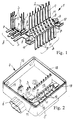
- Fig. 1 shows a sentence related generally designated 1 Contact parts 2 and 3 for a housing base part 4, which together with a Protective cover (not shown) a terminal box for a (not shown) Electric motor forms.
- the electric motor is preferably for one Heating pump used.
- the bottom part of the housing has, which faces the electric motor, a molded socket 5 with which the finished terminal box is attached to the electric motor becomes.
- the motor has a known plug receptacle, whose contact parts are electrically connected to the stator of the motor.
- the housing base part 4 also has a socket connection 6 into which a power cord is plugged in to the terminal box and thus the electric motor connected to it with electrical energy supply.
- the set 1 from the interconnected contact parts 2 and 3 is made in a known technique by punching and bending from a blank made of electrically conductive material.
- a Group A from the contact parts 2 and a group B from the contact parts 3 provided, the group A connecting to the electric motor manufactures while group B for connection to the power cord is thought.
- Most contact parts 2, 3 have an outer plug-in or Contact section 7, a middle section 8 and an inner connection section 9, with the sections 9 to the aforementioned control parts and functional parts (not shown) of the terminal box are electrically connected become.
- Some contact parts can also be used as temperature line parts be formed and therefore have instead of a plug-in cut a sensing section 10 as a contact section. These contact parts are also connected with corresponding functional parts, so that a Electric motor is automatically switched off in the event of overheating.
- the individual contact parts 2 and 3 of the in a first process step Contact part set 1 produced by stamping and bending are, for example by two connecting webs at their central section 8 with one another prepositioned connected. In this way, the contact parts form 2, 3 the coherent set 1, which is to be poured into the housing base part is used.
- the next step in the process is the casting of the housing base part 4 2.
- a corresponding casting mold is used in known technology designed with which the desired shape of the housing base part will be produced.
- the housing base part molded from plastic material 4 can in addition to the outer jack 5 and the power connector 6 also have inner stabilizing strips 12, 13 and 14, in which the inner connection section 9 cast contact parts 2 and 3 is.
- the contact part set 1 which is prefabricated correctly, is converted into the corresponding one Casting mold inserted and fixed, after which the casting is carried out.
- the now cast contact part set 1 removed from the mold and preferably subjected to a punching process around the connecting webs 11 between the contact parts 2 and 3 so that the Contact parts are then completely separated from each other. Subsequently through the punching process at the separation points in the area the removed connecting webs in the housing base part Punch holes 16 are sealed again, using a potting compound he follows.
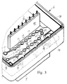
- first pouring paths in the bottom part of the housing are formed by using the mold for the housing base part rib-like projections is provided. These include first pouring paths at least stretches 15 between the points 16 of those to be removed Connecting webs 11, but can also these bottom wall locations Include the bottom part of the housing, as can be clearly seen in FIG. 3.
- first pouring paths at least stretches 15 between the points 16 of those to be removed Connecting webs 11, but can also these bottom wall locations Include the bottom part of the housing, as can be clearly seen in FIG. 3.
- Fig. 4 shows the housing base part 4 after the punching process, and one recognizes that there are no longer any connecting webs 11 at the punching points 16 are seen.
- the punching points or punching holes are poured out 16 with a suitable sealing compound.
- the cast and punched Housing bottom part 4 inserted into a corresponding shape, in which the Potting compound is entered with pressure. Via the first pouring paths the sealing compound then reaches all the punch holes 16 and closes this.
- the housing base part 4 thus produced is then the final assembly fed, d. H. it will be the aforementioned control and functional parts mounted in the housing base part 4, which may already be on a circuit board can be pre-assembled.
- Fig. 5 shows the housing base part 4 after pouring with potting compound. It can be seen that the casting compound is a coherent Network 17 forms, which has plug-like extensions, with which the punched holes 16 in the bottom wall of the housing base part 4th are filled out.
- the housing base part 4 at its upper edge with a circumferential groove 18 are provided, which also when casting the housing base part is also formed, by appropriate training of the mold for the housing base part.
- a circumferential groove 18 simultaneously with the Pour out the aforementioned punch holes 16 with casting compound to be able to form an elastic sealing ring therein second pouring paths provided.
- z. B. three more pouring paths 19 provided by the locations that form the later punch holes 16, go out and to the side wall of the Bottom of the housing run. From there they extend on the inside the side wall of the housing base part upwards to the upper edge of the Housing base part and open into the circumferential groove 18.
- punch holes 16 in the bottom wall of the housing base part with the sealing Potting compound are poured out at the same time Proportion of the casting compound via the further pouring paths 19 to the circumferential groove 18 and fills it completely to form an annular in this circumferential groove Form sealing insert 20.
- a potting compound advantageously chosen an elastic material so that in the circumferential groove elastic sealing insert is created when attaching a cover part yields in an elastically sealing manner on the housing base part.
- This sealing layer preferably includes that Area of the housing base part, which later on a contact area of the Housing of the electric motor rests.
- the sealing layer 22 formed on the underside 21 of the housing base part so that it surrounds the molded socket 5 of the housing base part, as can be seen from Fig. 6. This ensures that the Mating jack of the electric motor, in which the jack 5 of the Housing bottom part is inserted, compared to the atmospheric Environment is moisture-proof, so no moisture can penetrate into the electric motor from the environment. Furthermore the sealing layer cannot get lost because it is rigid with the Housing base material is positively connected.
- an elastic potting compound is used to make a to achieve perfect moisture sealing.
- the manufacture of the Sealing layer 22 takes place simultaneously with the potting of the punch holes 1 6 in the area of the removed connecting webs 1 1 in the housing base part 4 cast-in contact parts 2, 3.
- the punch holes selected for this on the underside 21 of the housing base part.
- the mold for this is also in this case Potting the potting compound in the area of the sealing layer to be produced 22 provided with a corresponding negative training.
Landscapes
- Engineering & Computer Science (AREA)
- Power Engineering (AREA)
- Motor Or Generator Frames (AREA)
- Manufacturing Of Electrical Connectors (AREA)
- Connector Housings Or Holding Contact Members (AREA)
Applications Claiming Priority (2)
| Application Number | Priority Date | Filing Date | Title |
|---|---|---|---|
| DE10027249 | 2000-05-31 | ||
| DE10027249A DE10027249A1 (de) | 2000-05-31 | 2000-05-31 | Verfahren zum Herstellen eines Gehäusebodenteils eines aufsteckbaren Klemmenkastens für einen Elektromotor |
Publications (3)
| Publication Number | Publication Date |
|---|---|
| EP1164687A2 true EP1164687A2 (fr) | 2001-12-19 |
| EP1164687A3 EP1164687A3 (fr) | 2003-06-11 |
| EP1164687B1 EP1164687B1 (fr) | 2004-03-31 |
Family
ID=7644383
Family Applications (1)
| Application Number | Title | Priority Date | Filing Date |
|---|---|---|---|
| EP01112754A Expired - Lifetime EP1164687B1 (fr) | 2000-05-31 | 2001-05-25 | Procédé de fabrication du fond d'un boîtier de bornes amovible pour un moteur électrique |
Country Status (2)
| Country | Link |
|---|---|
| EP (1) | EP1164687B1 (fr) |
| DE (2) | DE10027249A1 (fr) |
Cited By (2)
| Publication number | Priority date | Publication date | Assignee | Title |
|---|---|---|---|---|
| WO2005029681A1 (fr) * | 2003-09-02 | 2005-03-31 | Sew-Eurodrive Gmbh & Co. Kg | Moteur electrique |
| EP3133696A1 (fr) * | 2015-08-19 | 2017-02-22 | Continental Automotive GmbH | Dispositif de mise en contact et procede de fabrication |
Family Cites Families (5)
| Publication number | Priority date | Publication date | Assignee | Title |
|---|---|---|---|---|
| US4845396A (en) * | 1986-08-19 | 1989-07-04 | Capsonic Group, Inc. | Motor brush holder assembly |
| US5636431A (en) * | 1991-01-18 | 1997-06-10 | Swf Auto-Electric Gmbh | Method of manufacturing an electric motor |
| DE4101368C2 (de) * | 1991-01-18 | 2000-04-06 | Teves Gmbh Alfred | Elektrischer Motor und Verfahren zu seiner Herstellung |
| DE4330977C2 (de) * | 1993-09-13 | 1996-04-18 | Duerrwaechter E Dr Doduco | Gehäuse aus Kunststoff, insbesondere zum Aufnehmen elektrischer Bauteile |
| DE9315914U1 (de) * | 1993-10-19 | 1993-12-23 | Grundfos A/S, Bjerringbro | Steckkontaktsatz für eine steckbare elektrische Anschlußeinrichtung für den Elektromotor einer Heizungspumpe |
-
2000
- 2000-05-31 DE DE10027249A patent/DE10027249A1/de not_active Ceased
-
2001
- 2001-05-25 DE DE50101817T patent/DE50101817D1/de not_active Expired - Lifetime
- 2001-05-25 EP EP01112754A patent/EP1164687B1/fr not_active Expired - Lifetime
Cited By (2)
| Publication number | Priority date | Publication date | Assignee | Title |
|---|---|---|---|---|
| WO2005029681A1 (fr) * | 2003-09-02 | 2005-03-31 | Sew-Eurodrive Gmbh & Co. Kg | Moteur electrique |
| EP3133696A1 (fr) * | 2015-08-19 | 2017-02-22 | Continental Automotive GmbH | Dispositif de mise en contact et procede de fabrication |
Also Published As
| Publication number | Publication date |
|---|---|
| DE10027249A1 (de) | 2001-12-13 |
| EP1164687A3 (fr) | 2003-06-11 |
| DE50101817D1 (de) | 2004-05-06 |
| EP1164687B1 (fr) | 2004-03-31 |
Similar Documents
| Publication | Publication Date | Title |
|---|---|---|
| EP0590644B1 (fr) | Procédé pour surmoulage de grille de connexion | |
| EP1199913B1 (fr) | Méthode de fabrication d'unités comprenant une feuille de circuit et un boítier de support | |
| EP1133012B2 (fr) | Boîtier de bornes enfichable | |
| EP1233232A2 (fr) | Dispositif d'éclairage | |
| DE10329843A1 (de) | Verfahren zum wasserdichten Abdichten eines Leistungsschaltkreisabschnittes und Leistungsmodul mit einem derartigen Leistungsschaltkreisabschnitt | |
| DE10354283A1 (de) | Verbinder mit durch äusserer Abdeckung abgedecktem Anschlusstück | |
| DE4013509C2 (de) | Verfahren zur Herstellung von Steckern mit einem Kunststoff-Gehäuse und eingebetteten Kontaktzungen | |
| DE19757587C2 (de) | Drathverbindungsstruktur für Verbinder und Herstellungsverfahren hierfür | |
| DE19622895A1 (de) | Anschlußvorrichtung sowie Verfahren zu deren Herstellung | |
| DE3921889A1 (de) | Endrahmen eines kleinen motors | |
| DE102004019613B4 (de) | Verbinder und Verfahren zum Ausbilden desselben | |
| DE69406516T2 (de) | Steckeranordnung mit Stecker- und Steckeraufnahmeteilen mit wasserabstossenden Platten zur Vermeidung von Stromverlusten | |
| EP3221935B1 (fr) | Dispositif de liaison électrique et procédé de production dudit dispositif de liaison électrique | |
| EP1164687B1 (fr) | Procédé de fabrication du fond d'un boîtier de bornes amovible pour un moteur électrique | |
| DE60124749T2 (de) | Verbindungsgehäuse und dessen herstellungsverfahren | |
| DE19719436A1 (de) | Spritzgußgehäuse | |
| EP1502324B1 (fr) | Pont de connecteur enfichable a tige creuse | |
| EP2787578A2 (fr) | Système électrique et procédé de fabrication d'un système électrique | |
| DE4224618C2 (de) | Verfahren zum Herstellen elektrischer Steckverbinder und nach dem Verfahren hergestellte Steckverbinder | |
| DE19755408A1 (de) | Baueinheit zum Einbau in ein elektrisches Gerät | |
| EP0392398B1 (fr) | Méthode pour produire et envelopper des minifusibles et microfusibles | |
| DE10320441B3 (de) | Komponententräger | |
| DE102005002513B4 (de) | Verfahren zur Herstellung einer Steckdose und eines Steckers einer Geräte-Steckvorrichtung sowie einer Platinen-Steckvorrichtung, sowie Steckdose und Stecker hergestellt nach einem derartigen Verfahren | |
| DE2165442C2 (de) | Verfahren zur Herstellung eines Steckverbinders | |
| DE2252657A1 (de) | Gehaeuse fuer elektrische kabelverbindungen |
Legal Events
| Date | Code | Title | Description |
|---|---|---|---|
| PUAI | Public reference made under article 153(3) epc to a published international application that has entered the european phase |
Free format text: ORIGINAL CODE: 0009012 |
|
| AK | Designated contracting states |
Kind code of ref document: A2 Designated state(s): AT BE CH CY DE DK ES FI FR GB GR IE IT LI LU MC NL PT SE TR |
|
| AX | Request for extension of the european patent |
Free format text: AL;LT;LV;MK;RO;SI |
|
| PUAL | Search report despatched |
Free format text: ORIGINAL CODE: 0009013 |
|
| AK | Designated contracting states |
Designated state(s): AT BE CH CY DE DK ES FI FR GB GR IE IT LI LU MC NL PT SE TR |
|
| AX | Request for extension of the european patent |
Extension state: AL LT LV MK RO SI |
|
| 17P | Request for examination filed |
Effective date: 20030712 |
|
| GRAP | Despatch of communication of intention to grant a patent |
Free format text: ORIGINAL CODE: EPIDOSNIGR1 |
|
| 17Q | First examination report despatched |
Effective date: 20030912 |
|
| GRAS | Grant fee paid |
Free format text: ORIGINAL CODE: EPIDOSNIGR3 |
|
| GRAA | (expected) grant |
Free format text: ORIGINAL CODE: 0009210 |
|
| AKX | Designation fees paid |
Designated state(s): DE FR GB IT |
|
| AK | Designated contracting states |
Kind code of ref document: B1 Designated state(s): DE FR GB IT |
|
| REG | Reference to a national code |
Ref country code: GB Ref legal event code: FG4D Free format text: NOT ENGLISH |
|
| REG | Reference to a national code |
Ref country code: IE Ref legal event code: FG4D Free format text: GERMAN |
|
| REF | Corresponds to: |
Ref document number: 50101817 Country of ref document: DE Date of ref document: 20040506 Kind code of ref document: P |
|
| GBT | Gb: translation of ep patent filed (gb section 77(6)(a)/1977) |
Effective date: 20040712 |
|
| REG | Reference to a national code |
Ref country code: IE Ref legal event code: FD4D |
|
| ET | Fr: translation filed | ||
| PLBE | No opposition filed within time limit |
Free format text: ORIGINAL CODE: 0009261 |
|
| STAA | Information on the status of an ep patent application or granted ep patent |
Free format text: STATUS: NO OPPOSITION FILED WITHIN TIME LIMIT |
|
| 26N | No opposition filed |
Effective date: 20050104 |
|
| REG | Reference to a national code |
Ref country code: FR Ref legal event code: PLFP Year of fee payment: 16 |
|
| REG | Reference to a national code |
Ref country code: FR Ref legal event code: PLFP Year of fee payment: 17 |
|
| REG | Reference to a national code |
Ref country code: FR Ref legal event code: PLFP Year of fee payment: 18 |
|
| PGFP | Annual fee paid to national office [announced via postgrant information from national office to epo] |
Ref country code: DE Payment date: 20200527 Year of fee payment: 20 Ref country code: FR Payment date: 20200519 Year of fee payment: 20 |
|
| PGFP | Annual fee paid to national office [announced via postgrant information from national office to epo] |
Ref country code: IT Payment date: 20200528 Year of fee payment: 20 Ref country code: GB Payment date: 20200522 Year of fee payment: 20 |
|
| REG | Reference to a national code |
Ref country code: DE Ref legal event code: R071 Ref document number: 50101817 Country of ref document: DE |
|
| REG | Reference to a national code |
Ref country code: GB Ref legal event code: PE20 Expiry date: 20210524 |
|
| PG25 | Lapsed in a contracting state [announced via postgrant information from national office to epo] |
Ref country code: GB Free format text: LAPSE BECAUSE OF EXPIRATION OF PROTECTION Effective date: 20210524 |