EP1164723A2 - Procédé de synchronisation d'au moins une station mobile dans un réseau de télécommunication mobile ayant une structure de canal de synchronisation modifiée - Google Patents
Procédé de synchronisation d'au moins une station mobile dans un réseau de télécommunication mobile ayant une structure de canal de synchronisation modifiée Download PDFInfo
- Publication number
- EP1164723A2 EP1164723A2 EP01460036A EP01460036A EP1164723A2 EP 1164723 A2 EP1164723 A2 EP 1164723A2 EP 01460036 A EP01460036 A EP 01460036A EP 01460036 A EP01460036 A EP 01460036A EP 1164723 A2 EP1164723 A2 EP 1164723A2
- Authority
- EP
- European Patent Office
- Prior art keywords
- synchronization
- basic
- sequence
- reinforced
- interval
- Prior art date
- Legal status (The legal status is an assumption and is not a legal conclusion. Google has not performed a legal analysis and makes no representation as to the accuracy of the status listed.)
- Withdrawn
Links
Images







Classifications
-
- H—ELECTRICITY
- H04—ELECTRIC COMMUNICATION TECHNIQUE
- H04W—WIRELESS COMMUNICATION NETWORKS
- H04W56/00—Synchronisation arrangements
- H04W56/0055—Synchronisation arrangements determining timing error of reception due to propagation delay
-
- H—ELECTRICITY
- H04—ELECTRIC COMMUNICATION TECHNIQUE
- H04B—TRANSMISSION
- H04B7/00—Radio transmission systems, i.e. using radiation field
- H04B7/24—Radio transmission systems, i.e. using radiation field for communication between two or more posts
- H04B7/26—Radio transmission systems, i.e. using radiation field for communication between two or more posts at least one of which is mobile
- H04B7/2662—Arrangements for Wireless System Synchronisation
- H04B7/2671—Arrangements for Wireless Time-Division Multiple Access [TDMA] System Synchronisation
- H04B7/2678—Time synchronisation
- H04B7/2681—Synchronisation of a mobile station with one base station
-
- H—ELECTRICITY
- H04—ELECTRIC COMMUNICATION TECHNIQUE
- H04J—MULTIPLEX COMMUNICATION
- H04J13/00—Code division multiplex systems
- H04J13/10—Code generation
-
- H—ELECTRICITY
- H04—ELECTRIC COMMUNICATION TECHNIQUE
- H04W—WIRELESS COMMUNICATION NETWORKS
- H04W92/00—Interfaces specially adapted for wireless communication networks
- H04W92/04—Interfaces between hierarchically different network devices
- H04W92/10—Interfaces between hierarchically different network devices between terminal device and access point, i.e. wireless air interface
Definitions
- the invention relates to a method for the synchronization of at least one mobile station with a base station within a mobile telecommunications network.
- the invention can be applied especially in UMTS-FDD (Universal Mobile Telecommunication System-Frequency Division Duplex) type third-generation telecommunications networks.
- UMTS-FDD Universal Mobile Telecommunication System-Frequency Division Duplex
- a mobile station is synchronized with the base station of a cell of the network by means of two channels issued by the base station, a synchronization channel and a common communications channel called a CPICH (common pilot channel) channel.
- This synchronization operation consists in determining the time base of the base station of the cell and the scrambling code associated with it.
- the UMTS-FDD radio frames have a duration of 10 ms, that is 38400 chips, and can be subdivided into 15 successive time slots with a duration of about 666.67 ⁇ s each, giving 2560 chips.
- the operation of synchronization can be subdivided into three elementary steps designed respectively to determine the time base of the base station, the beginning of the UMTS-FDD radio frames sent and the associated scrambling code.
- the first two elementary steps are performed on the synchronization channel.
- the synchronization channel is constituted by two elementary channels sent simultaneously: the primary synchronization channel and the secondary synchronization channel conveying respectively the primary synchronization code and the secondary synchronization codes.
- the primary synchronization code is a real code that is identical for all the cells of the UMTS-FDD network. It is sent identically on the in-phase component and the quadrature component in the form of a string of chips with a duration of about 66.67 ⁇ s, giving 256 chips, at the beginning of each time slot. Each of these strings of chips is called a primary synchronization burst.
- the mobile station filters the received signal by means of a digital correlation filter matched with the primary synchronization code. The correlation values at output of this filter are accumulated circularly with a period equal to the duration of a time slot.
- the secondary synchronization codes are also real codes that are sent identically on the in-phase component and the quadrature component in the form of strings of chips with a duration of about 66.67 ⁇ s, giving 256 chips, at the beginning of each time slot simultaneously with the primary synchronization code.
- Each of these strings of chips is designated as a secondary synchronization burst.
- a synchronization burst results from the addition of a primary synchronization burst and a secondary synchronization burst sent simultaneously.
- a synchronization burst of this kind is therefore sent at the beginning of each time slot into the synchronization channel.
- Each secondary synchronization code carries a respective piece of information known as a synchronization symbol taken out of a finite alphabet ⁇ 1, 2, ..., 16 ⁇ .
- the 16 secondary synchronization codes are obtained by taking the product, chip by chip, of a parent secondary code Cm common to all the secondary synchronization codes and a Walsh code W 1 , W 2 , ..., or W 16 proper to each synchronization symbol.
- the secondary synchronization channel of a cell is characterized by a sequence of 15 consecutive synchronization symbols corresponding to the secondary synchronization codes received during a radio frame (15 time slots). This sequence is repeated at each radio frame on the secondary synchronization channel. This sequence characterizes a group of eight scrambling codes. There are 64 possible groups of codes.
- the decoding of the secondary synchronization channel gives a part of the secondary synchronization signal comprising a portion or the totality of the sequence of synchronization symbols. This part then makes it possible to identify a group of scrambling codes and determine the position of the beginning of the radio frame. It must be noted that the mobile station does not necessarily need to decode a part enclosing 15 symbols. Three consecutive symbols are enough to determine the sequence entirely. However, to have sufficient decoding quality in the presence of disturbances, it is more prudent to consider a part of more than three elements of the sequence.
- the second elementary synchronization step thus makes it possible to determine the group of scrambling codes and the beginning of the frame. Once the group of codes is identified, the mobile station must determine the scrambling code of the cell.
- the common pilot channel CPICH that conveys a known sequence of symbols to all the mobile stations previously scrambled with the scrambling code of the cell is "unscrambled" with each of the eight possible codes in order to retrieve the scrambling code used by the considered cell.
- the scrambling code of the cell is then identified. This is the aim of the third elementary synchronization step.
- the mobile station has to get synchronized with a cell, it performs these three elementary steps.
- An aim of the invention relates more particularly to the case of a mobile station that is already synchronized with a current cell but seeks to get synchronized with a new cell, generally an adjacent cell for the purpose for example of determining if there is reason to make a handover (or inter-cell transfer) to this new cell.
- a mobile station is said to be in connected mode with a cell when it is communicating with the base station of this cell. The mobile station then goes into standby mode when the communication is terminated.
- a first situation is the case where a mobile station in connected mode with a first UMTS-FDD cell at a certain carrier frequency seeks to get synchronized with a base station of a second UMTS-FDD cell using the same carrier frequency.
- the mobile station then, in addition to the signals coming from the first cell, receives the synchronization signals and the signals from the CPICH channel of the base station of the second cell. It then applies the above three elementary operations to these signals to get synchronized with the base station of the second cell.
- a second situation is the case where a mobile station in connected mode with a first UMTS-FDD cell on a first carrier frequency seeks to get synchronized with the base station of a second UMTS-FDD cell using a second carrier frequency different from the first one.
- the network then provides for time windows in the radio link connecting the base station of the first cell to the mobile station, during which no signal travels between the two.
- the mobile station then has these time windows available to get synchronized with the base station of the second cell.
- the network opens these time windows by increasing the information bit rate before and/or after these time windows. These time windows are hereinafter designated by transmission gaps.
- the technique used to create a transmission gap by temporarily increasing the bit rate before and/or after this interval is hereinafter called the compressed mode.
- a third situation is the case where a mobile station in connected mode with a GSM cell at a certain carrier frequency seeks to get synchronized with a base station of a UMTS-FDD cell.
- the data elements are transmitted in a multiframe-26 type GSM multiframe.
- a multiframe-26 consists of 26 consecutive GSM frames or TDMA frames.
- the structure of a multiframe-26 is such that one in every 26 GSM frames is vacant and left unoccupied to carry out measurements. Furthermore, it may happen that, in the current GSM frame, time slots are not used for data transmission. The mobile station can then use all these vacant time slots to get synchronized with the base station of a UMTS-FDD cell.
- a fourth situation is the case where the mobile station is in standby mode on a UMTS-FDD cell. Even if the mobile station is not in connected mode with this cell, it continues to receive information from the network through this cell and has to be capable of getting synchronized with the base station of another cell if it moves in another cell. The mobile station must also make measurements on the neighbouring cells in order to see if it has not changed cells. It therefore needs to get synchronized with the neighbouring cell. During the standby mode, the mobile station therefore alternates between two modes: an active standby mode and a dormant mode. In dormant mode, most of the elements of the mobile station are no longer powered. This is in order to limit power consumption.
- the mobile station In active standby mode, the mobile station performs the necessary measurements and listens to certain broadcasting channels.
- the mobile station goes into active standby mode at regular intervals during a time window of a length sufficient to make reliable measurements. The size of these time windows however is reduced to limit the power consumption of the mobile station.
- a fifth situation is the case where the mobile station is in standby mode on a GSM cell. Even when it is on a GSM cell, a mobile station should be capable of receiving messages coming from a UMTS-FDD cell or of knowing if it is going from a GSM cell to a UMTS-FDD cell. As described here above, the mobile station must listen to the UMTS-FDD cell at regular intervals.
- the term “effective acquisition time” shall designate the time during which the synchronization signal is acquired.
- the “total acquisition time” is the time that elapses between the beginning and the end of the acquisition of the synchronization signal. The total acquisition time is greater than the effective acquisition time if the signal is acquired during several non-consecutive time intervals.
- the term “window time” designates the period of the time window used to carry out a measurement of synchronization or the sum of the periods of the time windows used if there are several of them.
- the first problem relates to the loss of resources for the current cell.
- the windows have to be created by the network by setting up transmission gaps to enable the mobile station to receive the synchronization bursts. During these transmission gaps, the mobile station cannot receive data coming from the current cell. This has an effect on the maximum bit rate of the radio link or on the quality of decoding its data elements, leading to a waste of useful resources.
- the GSM mobile stations have to carry out not only measurements on the UMTS-FDD cells but also measurements on the GSM cells. The measurement windows exist naturally in the GSM system and it is not necessary to set up transmission gaps.
- These windows consist of the time slots of the TDMA frames not used for the transmission of data with the mobile station and of the unoccupied TDMA frame within the multiframe-26. In this situation, the window time is therefore fixed.
- the same type of problem arises with any mobile radio system permitting handovers to the UMTS-FDD system. It is therefore preferable for the effective acquisition time to be as short as possible.
- the second elementary synchronization step is all the more efficient as the number of synchronization bursts acquired is great. If the second elementary step uses several time windows, its performance is better when the radio frame parts covered by these time windows do not overlap or overlap as little as possible. Complying with this constraint then means that there is less flexibility for deciding on the instants of opening the time windows.
- the use of several time windows raises another problem: for an effective acquisition time, the window time should be increased as compared with the case where the acquisition is done with a single time window. Indeed, when a mobile station opens a time window on a frequency different from the current frequency, the local oscillator of the mobile station takes a certain time to get stabilized at the new frequency. This time depends on the quality of the oscillator (and hence its cost of manufacture) and on the necessary frequency leap. Let T s be the stabilization time of the oscillator and T e the effective acquisition time needed to perform the synchronizing operation.
- the necessary window time is T e +2.T s , the factor 2 resulting from the fact that the frequency has to be changed twice in the time window, namely once at the beginning and once at the end of the time window.
- the necessary window time becomes T e +4.T s .
- the division of a time window into n windows gives rise to a divergence between the window time and the effective acquisition time. This divergence is equal to 2n.T s .
- the invention relates to a method for the synchronization of at least one mobile station with a base station within a mobile telecommunication network, comprising a step for the generation, by said base station, of a basic synchronization signal comprising N synchronization bursts per radio frame, called basic synchronization bursts, a step for the transmission of said basic synchronization signal during at least one radio frame of a synchronization channel, each of said N basic synchronization bursts being associated with a time slot of said radio frame and being transmitted during a time interval at the beginning of said associated time slot, and a step for the reception and processing of said basic synchronization signal by said at least one mobile station, characterised in that it furthermore comprises a step for the generation of an additional synchronization signal intended to be transmitted with said basic synchronization signal during said step for the transmission of the basic synchronization signal, said additional synchronization signal comprising at least one synchronization burst, called additional synchronization burst, said at least one additional synchronization burs
- each reinforced synchronization interval comprises at least one basic synchronization burst.
- the synchronization bursts are preferably distributed uniformly in said reinforced synchronization interval according to a time step and the duration of the reinforced synchronization interval is equal at most to 20% of that of the radio frame.
- This method may be used to synchronize the mobile station with a new base station within an UMTS type mobile telecommunication network, the mobile station being already synchronized with a first base station of said network.
- each base station can selectively take a state corresponding to periods of transmission of useful signals, especially synchronization signals and data signals, to the mobile station and a state corresponding to periods called non-transmission intervals during which the base station stops transmitting useful signals to said mobile station.
- the position of the non-transmission intervals from the first base station in the radio frame is determined so that the synchronization bursts of said reinforced synchronization interval proper to the new base station are transmitted by this new base station substantially during said non-transmission intervals.
- the method is used to synchronize a mobile station with a base station within a UMTS type mobile telecommunication network, the mobile station being already synchronized with a first base station of a GSM type mobile telecommunication network.
- time windows are present in the multiframes of the GSM type mobile telecommunication network during which no useful signal is transmitted.
- the instants of occurrence of the reinforced synchronization intervals are determined so as to limit the period of time at the end of which a synchronization interval coincides substantially with a time window of the GSM multiframe.
- the method is used to determine the position of a mobile station in a UMTS type mobile telecommunication network comprising at least three base stations.
- the base stations may selectively take a state corresponding to periods of transmission of useful signals, especially synchronization signals and data signals, to the mobile station and a state corresponding to periods called periods of silence during which no useful signal is transmitted.
- the invention also relates to a mobile telecommunication network comprising at least one mobile station and a plurality of base stations, each base station comprising means for the generation of a basic synchronization signal comprising N synchronization bursts per radio frame, called basic synchronization bursts, means for the transmission of said basic synchronization signal during at least one radio frame of a synchronization channel, each of said N synchronization bursts being associated with a time slot of said radio frame and being transmitted during a time interval at the beginning of said associated time slot, each mobile station furthermore comprising means for the reception and processing of said basic synchronization signal transmitted by one of said base stations to synchronize said mobile station with this base station, characterised in that it furthermore comprises means for the generation of an additional synchronization signal intended to be transmitted with said basic synchronization signal by said means of transmission of the basic synchronization signal, said additional synchronization signal comprising at least one synchronization burst, called additional synchronization burst, said at least one additional synchronization burst
- the invention while preserving the general structure of the frame of the synchronization channel, proposes the intensification, at regular times, of the synchronization signal during a short time interval, herein after called a reinforced synchronization interval or RSI.
- a reinforced synchronization interval or RSI a reinforced synchronization interval
- the cycle of activity of the synchronization channel of a base station is x%
- the invention proposes to make it go to y%, with y>x, on a time interval corresponding to the reinforced synchronization interval. This will reduce the effective acquisition time of the synchronization signal and thereby reduce the size or number of time windows needed for this acquisition.
- the cycle of activity of the synchronization channels is presently 10%.
- it is proposed to increase it during the RSI intervals.
- the cycle of activity of the synchronization channel is increased by increasing the number of synchronization bursts transmitted per time unit during the RSI interval.
- the initial frame structure of the synchronization channel is kept.
- the additional synchronization signal consists of one or more synchronization bursts called additional synchronization bursts hereinafter in the description. The process of the generation of these additional synchronization bursts is described further below.
- These additional synchronization bursts may be identical to bursts of the basic synchronization signal.
- the synchronization bursts of the basic synchronization signal are called basic synchronization bursts.
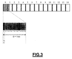
- Figures 1, 2, 3 and 4 show the synchronization bursts generated in a first embodiment of the method of the invention.
- the upper part 10 of Figure 1 shows the synchronization bursts (corresponding to the basic synchronization bursts according to the invention) in a standard UMTS-FDD frame.
- the synchronization bursts generated according to the first embodiment are shown under the standard UMTS-FDD frame in a UMTS-FDD frame referenced 100.
- ⁇ represents the time lag between the beginning of the first time slot of the RSI interval and the first additional burst, as well as the time lag between two successive additional bursts in one and the same time slot.
- the time lag between the last additional synchronization burst of a time slot and the first additional synchronization burst of the following time slot is taken to be equal to 2. ⁇ .
- ⁇ is called a time step and is expressed by a number of chips.
- the starting time slot of an RSI interval designates the first time slot whose beginning coincides with or follows the beginning of the RSI interval.
- the additional synchronization bursts can begin only at instants of the t+k. ⁇ type, where k is a relative integer.
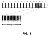
- D represents the duration of the reinforced synchronization RSI interval.
- the duration of the RSI interval is preferably small as compared with the duration of a radio frame. For example, it is equal to 20% of the radio frame.
- the reinforced synchronization interval extends from the beginning of the first time slot (number 0) of the radio frame up to the end of the third time slot (number 2).
- the first three time slots of the radio frame each comprise a basic synchronization burst and four additional synchronization bursts.
- the additional synchronization bursts correspond to the basic synchronization bursts of the other twelve time slots of the radio frame.
- the time step ⁇ is equal to 512 chips.
- the period of occurrence, referenced T, of the RSI intervals may vary in time.
- the position of the RSI interval in the frame may vary from one RSI interval to the other.
- the beginning of the RSI interval is positioned at the beginning of the fifth time slot (number 4) of the radio frame.
- the reinforced synchronization interval is then positioned on the fourth, fifth and sixth time slots of the UMTS-FDD frame.
- an RSI interval is not necessarily included in a radio frame. It may straddle two consecutive radio frames. This case is illustrated in Figure 9 (described further below in the description).
- the time step ⁇ has a minimum value of 256 chips so that the additional synchronization bursts do not overlap one another.
- the maximum value of ⁇ is 512 chips ( Figure 1).
- Figure 3 shows a case where ⁇ is equal to 256 chips.
- a time window with a duration of 1 ms is sufficient.
- an RSI interval always begins at the beginning of a time slot.
- the granularity of the instant of occurrence is equal to T TS , namely one time slot.
- the first synchronization burst of the RSI interval is therefore then a basic synchronization burst.
- the position of an RSI interval is therefore entirely defined by the number FN of the radio frame in which said RSI interval starts and by the number SLN of the time slot of this frame in which it starts.
- ⁇ positions of beginning of RSI interval in each time slot ⁇ being an integer proper to the RSI interval and designating the number of synchronization bursts per time slot entirely included in this RSI interval.
- t is the starting instant of the starting time slot of the RSI interval considered, then the RSI interval starts at one of the following instants: t-( ⁇ -1) ⁇ , t-( ⁇ -2) ⁇ ,..., t- ⁇ , or t, in other words at t-STN. ⁇ with STN ⁇ 0, 1, ..., ⁇ -1 ⁇ .
- the position of an RSI interval is therefore entirely defined by the FN number of the radio frame in which the starting time slot is located, the SLN number of the starting time slot in this frame and the STN number of the time steps between the beginning of the RSI interval and the beginning of its starting time slot.
- the duration of the RSI interval may also be variable. This makes it possible to reach various compromises: a long reinforced synchronization interval enables the mobile stations to acquire more synchronization bursts, thus improving the quality of the synchronization, but the trade-off here is that it is necessary to make bigger time windows so that the mobile stations can receive these synchronization bursts.
- the number c of synchronization bursts transmitted during an RSI interval varies according to the duration D of this interval and the time gap ⁇ between the synchronization bursts.
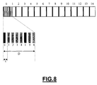
- Figure 4 shows an RSI interval whose duration is limited to 1.5 time slots.
- the RSI interval comprises synchronization bursts of the first eight time slots of the radio frame and the time step ⁇ is equal to 512 chips.
- the network is responsible for sending each mobile station the following parameters relating to a given set of RSI intervals called an RSI string:
- t F0 t F 0 + FN 0 ⁇ T F + SLN 0 ⁇ T TS - STN 0 ⁇
- s n 15 ⁇ FN n + ⁇ SLN n - STN n
- T / ⁇ ' is the integer expressing the period of occurrence in number of ⁇ ths of a time slot.
- the instant of occurrence t n is deduced therefrom by the formula (3). It must be noted that, for preferred values of ⁇ which give a regular spacing of the additional synchronization bursts, the instant of occurrence t n is substantially periodic. Indeed, it diverges from a periodic instant t 0 + n.T only for a maximum of ⁇ chips because ⁇ and ⁇ ' do not differ by more than one chip.
- the mobile stations are informed of the changes in value of the parameters FN 0 , SLN 0 , STN 0 , ⁇ , T and IN by a common signalling channel or individually by a dedicated signalling channel.
- the parameter ⁇ may be a constant of the network and, in this case, it is unnecessary to send it to the mobile stations.
- the position of the RSI intervals of this string in the radio frames is constant when the period of occurrence T is a multiple of the duration of the radio frame, namely when T/T F is an integer.
- T/T F is an integer.
- the generation of the compressed mode may be complex and may necessitate specific computations depending on the position of the transmission gap in the radio frame. It is therefore advantageous, for measurements on UMTS-FDD cells by a UMTS-FDD cell, that the transmission gap should have a fixed position in the radio frame, and that it should be the RSI interval that has a variable position.
- the RSI interval and the transmission gap will coincide at a given time if the position of the transmission gap is fixed.
- ⁇ will designate the function of ⁇ giving the number of synchronization bursts per time slot for time slots entirely included in the RSI interval. More generally, ⁇ depends both on ⁇ and the time slot number considered (the number 0 designating the starting time slot of the RSI interval). Indeed, if t is the starting instant of the starting time slot of the RSI interval then, for the time slot numbered n, the first additional synchronization burst will begin at the instant t+k. ⁇ , where k is the smallest integer such that t+k. ⁇ t+n.2560+256. In other words, where ⁇ x ⁇ , designates the smallest integer greater than or equal to x.
- ⁇ (n, ⁇ ) does not depend on n when n is sufficiently small, more precisely when n ⁇ 7.
- the table below gives a few preferred values of ⁇ providing for a substantially regular spacing of synchronization bursts during the RSI interval, as well as corresponding values of ⁇ (n, ⁇ ) for any n in an interval ⁇ 0,1,2,...,n c ⁇ .
- the value of n c is indicated in the last line of the table. ⁇ 256 284 319 320 321 365 426 511 512 ⁇ 10 9 8 8 8 7 6 5 5 n c + ⁇ 7 7 + ⁇ 7 14 14 14 + ⁇
- the duration D of the RSI interval can consist of up to eight time slots with a constant number of synchronization bursts per time slot. It is therefore considered here below that, for a given value of ⁇ , ⁇ is a constant number.
- each additional synchronization burst bears a synchronization symbol in ⁇ 1, 2, ..., 16 ⁇ .
- each additional synchronization burst is the addition of a primary synchronization burst generated by means of a primary synchronization code Cp', called an additional primary code, and a secondary synchronization code which is a product of a parent secondary code Cm', called an additional parent secondary code, and a Walsh code W 1 , W 2 , ..., W16 determined by the synchronization symbol.
- the additional synchronization bursts may be taken to be identical or different from the basic synchronization bursts.
- the primary code Cp' of the additional synchronization bursts is identical to the primary code Cp of the basic synchronization bursts.
- the parent secondary code Cm' of the additional synchronization bursts is identical to the parent, secondary code Cm of the basic synchronization bursts.
- the additional synchronization bursts are therefore taken to be identical to basic synchronization bursts. This case has the advantage of enabling the use of one and the same type of equipment to detect the basic synchronization signal and the additional synchronization signal.
- the duration of the time slot is a multiple of ⁇ .
- a circular accumulation is then done with a period equal to the duration of a time slot. In the invention, this accumulation then generates not only correlation peaks due to the basic synchronization bursts but also correlation peaks due to the additional synchronization bursts.
- a mobile station not implementing the invention may assume that a significant correlation peak due to the additional synchronization bursts is a correlation peak due to the basic synchronization bursts, and there is a risk that this mobile station will take these additional correlation peaks to be starts of time slots.
- This risk is relatively high when the mobile station not implementing the invention accumulates the correlations of the basic synchronization signal on a small number of time slots. This risk is also higher when the RSI interval is long.
- D is higher than a time slot, advantageously the other preferred values of ⁇ , namely 284, 319, 321, 365, 426 or 511 chips, are used.
- a second method to prevent this problem of descending compatibility consists in generating additional synchronization bursts that are different from the basic synchronization bursts.
- the method takes, for example, primary codes Cp and Cp' that are different and, if need be, secondary parent codes Cm and Cm' that are also different.
- the codes Cp' and Cm' are chosen so as to present efficient properties of self-correlation and inter-correlation.
- Cp' is constructed in the same way as Cp to enable a hierarchical correlation or a correlation with a Golay correlator so as to reduce the complexity of the matched correlation filter.
- the mobile station can then distinguish between the correlation peaks due to the basic synchronization bursts and those due to the additional synchronization bursts.
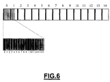
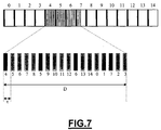
- FIG. 5 A second embodiment of the method of the invention is illustrated in Figures 5, 6, 7 and 8.
- the RSI interval contains redundant synchronization bursts.
- Figure 5 and Figure 6 respectively show an UMTS-FDD radio frame generated by the second embodiment of the method of the invention with ⁇ being equal respectively to 512 chips and 256 chips.
- the reference ⁇ is given to the finite sequence of the 15 consecutive synchronization symbols proper to a cell of the network, each of these symbols being sent at the beginning of one of the 15 time slots of the radio frame in the form of a secondary basic synchronization burst.
- This sequence ⁇ called a basic sequence, may be considered to be an application of the set ⁇ 0, 1,...,14 ⁇ , of the time slot numbers in the radio frame to the set ⁇ 1, 2, ..., 16 ⁇ of the synchronization symbols.
- This application associates a synchronization symbol ⁇ (i), corresponding to the secondary code transmitted at the beginning of this time slot, with any time slot i.
- ⁇ (i) is used, for any relative integer i, to denote the value of ⁇ (i mod 15) where "a mod b" is the remainder of the Euclidean division of "a” by "b".
- ⁇ (15) ⁇ (0)
- ⁇ (16) ⁇ (1), etc.
- the sequence of synchronization symbols to be transmitted by the additional synchronization signal is a function of the sequence ⁇ .
- a sequence ⁇ (0), ⁇ (1), ..., ⁇ (15. ⁇ -1) of 15. ⁇ synchronization symbols is defined.
- This sequence is called a additional sequence and is defined as a function of the sequence ⁇ such that the ⁇ symbols ⁇ (i ⁇ ), ⁇ (i ⁇ +1), ..., ⁇ ((i+1) ⁇ -1) are associated with the time slot i. It may be recalled that ⁇ designates the number of synchronization bursts per time slot entirely included in the RSI interval.
- ⁇ is an application of ⁇ 0, 1, ..., 15. ⁇ -1 ⁇ to ⁇ 1, 2, ..., 16 ⁇ .
- ⁇ (x mod (15. ⁇ )) ⁇ (x) is also noted for every integer x.
- the synchronization bursts transmitted during the RSI interval respectively bears the synchronization symbols ⁇ (u ⁇ -v), ⁇ (u ⁇ -v+1), ..., ⁇ (u ⁇ -v+c-1).
- the synchronization symbols transmitted during the RSI interval are taken by circularly travelling through the sequence ⁇ starting from the first synchronization symbol ⁇ (u. ⁇ -v) associated with the starting instant of the RSI interval.
- ⁇ (i. ⁇ ) ⁇ (i).
- the synchronization burst at the beginning of the time slot is always a basic synchronization burst.
- the sequence ⁇ may be defined in many ways as a function of the sequence ⁇ .
- several possible formulations of ⁇ have been proposed that make it possible especially to implement the first and second embodiments explained here above as well as other embodiments.
- i designates a time slot number
- u designates the number of the starting time slot of the RSI interval (u is referenced SLN in the formulae (3) and (4))
- d designates the number of basic synchronization bursts included in the RSI interval.
- ⁇ is defined as follows:
- the additional sequence is then generated in the same way as for the first embodiment but starting from the element ⁇ (u+1) of the basic sequence associated with the time slot, numbered u+1 mod 15, following the starting time slot.
- ⁇ is defined as follows:
- the additional sequence is then generated by circularly taking up the elements of the basic sequence and by starting from the element ⁇ (0) associated with the first time slot of the radio frame.
- the result of this step is identical to that of the second assigning step of the first and second embodiments.
- ⁇ is defined as follows:
- the additional sequence restricted to the elements not associated with a basic synchronization burst is then generated by circularly taking up the elements of the basic sequence and starting from the element ⁇ (0) associated with the first time slot of the radio frame.
- the secondary codes to be transmitted by the additional synchronization signal is therefore a function of the sequence ⁇ .
- the elementary synchronization steps become the following:
- the third step of synchronization it is possible to eliminate the third step of synchronization and make the measurement only with the first two steps.
- To carry out a measurement on a cell it is necessary to be able to isolate the cell in question from the other cells using the same frequency. This isolation of the cell considered is possible through its scrambling code. Indeed, there are 512 different scrambling codes, and their allocation to the different cells of the network is planned so that the neighbouring cells do not use the same scrambling code. Thus, the number of the scrambling code locally identifies a cell.
- the third synchronization step then enables the measurement of a level of power for each scrambling code of the group of codes by using the CPICH.
- This third step is therefore used to measure the reception power of each cell respectively corresponding to the scrambling codes for a frame synchronization obtained during the second step and therefore to ascertain that the cell is received with sufficient power or that the frame synchronization is properly done.
- the third step requires a greater window time.
- a cell does not always have the approximate shape of a disk. It may also have the approximate shape of an angular sector. In this case, several cells corresponding to different angular sectors of one and the same disk may have base stations placed in the centre of this disk.
- the measurement consists in determining only the frame synchronization, it is enough to stop at the second elementary step.
- two neighbouring cells that do not have the same frame synchronization are necessarily on distinct sites and therefore have distinct code groups, which enables them to be distinguished during the second synchronization step.
- Each base station of the network can selectively take a state corresponding to periods of transmission of useful signals, especially synchronization signals and data signals, to the mobile station and a state corresponding to periods corresponding to the previously defined transmission gaps during which the base station concerned stops sending the useful signals towards the mobile station.
- the position of the transmission gaps of the first base station in the radio frame is determined so that the synchronization bursts of said reinforced synchronization interval proper to the second base station are sent by this base station during the transmission gaps of the first base station.
- This positioning of the transmission gaps is possible when the instants of occurrence of the RSI intervals of the second base station are known to the network in the time base of the first base station.
- this is the case when the network approximately knows the time difference between the time bases of the two base stations. Indeed, since the network knows the instants of occurrence of the RSI intervals in the time base of the second base station as well as the time difference between the two time bases, it can deduce therefrom the instants of occurrence in the time base of the first base station. To know this time difference, the network can estimate it at the time of the handovers by comparing the measurements of synchronization made by the mobile station respectively for the two cells. This estimation is stored in a database of the network.
- the precision with which the time difference is estimated deteriorates in time with the drift of the time bases of each base station, but it is updated whenever a handover is made.
- a second and third method for knowing the instants of occurrence of the RSI intervals of the new base station expressed in the time base of the first base station shall be described further below.
- the network makes the mobile station enter the compressed mode. Since the network knows the instants of occurrence of the RSI intervals of the neighbouring cell expressed in the time base of the current cell, it can then place the mobile station in compressed mode during the RSI interval of the neighbouring cell.
- a mobile station could have the RSI interval of all the cells of the network in a single time window if these intervals are substantially simultaneous in all the cells.
- the duration of the time window can thus be reduced accordingly. If, however, the mobile station nevertheless opens a 10 ms window containing the RSI interval, it will have 28 synchronization bursts available in the case of Figure 3 and 29 synchronization bursts available in the embodiment of Figure 6 instead of 15 synchronization bursts as in the prior art.
- the reinforced synchronization signal can also be used when preparing a handover on cells with a same carrier frequency as the current cell.
- the mobile station does not know the exact time position of the RSI interval (otherwise, the mobile station would have been already synchronized) but an approximate position of it.
- the duration of the time window needed is therefore the sum of :
- the stabilization time of the local oscillator does not have to be taken into account since there is no change in frequency to be made.
- the mobile station In a mode called a reselection mode, the mobile station already has information on these neighbouring cells. In particular, it has approximate knowledge of the scrambling code and/or the time base. In practice, it can remove the need for the synchronization channel by making power measurements directly on the CPICH channel. However, since the knowledge of the time base is only approximate, the mobile station must then make measurements for all the possible time shifts of the time base. The number of operations this necessitates is especially great as the degree of approximation with which the time base is known is generally great. According to the invention, the synchronization channel is optimized to reduce the acquisition time of the synchronization information. It is then more valuable to search the time base of the cell in getting synchronized firstly on the synchronization channel. Once synchronized, the mobile station has only a power measurement to make.
- the method of the invention can also be used in the context of a mobile station in connected mode or standby mode with a cell of the GSM network.
- This mobile station seeks to get synchronized with an UMTS-FDD cell to take a measurement of power of the signal sent by this cell. To do so, it uses the time windows provided by the GSM network (for example between transmission on the uplink and reception on the downlink or between reception on the downlink and transmission on the uplink or during the unoccupied frame of the multiframe) to acquire the synchronization bursts included in the RSI interval.
- the parameters of the RSI string are determined so as to limit the period at the end of which a reinforced synchronization interval coincides with a time window of the GSM network.
- the period of occurrence of the RSI intervals should not be a multiple of the TDMA frame duration.
- the time position of the RSI intervals with respect to the beginning of the TDMA frame then gets shifted at each new occurrence and the RSI interval ultimately coincides with a natural time window of the GSM system.
- the method of synchronization of the invention can also be used to determine the position of a mobile station.
- the synchronization bursts of the RSI interval of a base station are used as a localization signal. It may be recalled that the position of a mobile station is determined with respect to the known positions of fixed base stations or known paths (base stations can be placed on board vehicles such as trains and, in this case, they may be used for positioning only if the network at all times knows their position). This determining is done by computing the differences in distance between the mobile station and each of the base stations of a pair of base stations included among at least three base stations of the network.
- the term "dominant base station” designates the base station sending the localization signal that is received with the highest signal-to-noise ratio. In general, the dominant base station is the current base station.
- a reinforced synchronization signal The group of the synchronization bursts of the RSI interval is hereinafter called a reinforced synchronization signal.
- the RSI intervals of the different base stations do not overlap and that the period T of occurrence of the RSI interval is the same for all the base stations. Furthermore, when the reinforced synchronization signal is sent by a base station, the base stations of the adjacent cells interrupt their transmission so that the reception of the reinforced synchronization signal is not disturbed.
- the time interval during which the transmission is interrupted is hereinafter called “period of silence” and is referenced S in the figures. The formation of periods of silence is not necessary in the case of the preparation of a handover.
- the mobile station cannot receive the synchronization channel of a neighbouring cell because the reception is excessively disturbed by the dominant base station (corresponding to the cell in which the mobile station is located), it means that a handover is not necessary since the signals of the current cell are received more clearly than those of the neighbouring cell considered.
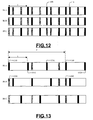
- Figure 12 illustrates this first case with a network comprising three base stations of mutually neighbouring cells BS A, BS B and BS C.
- the base station BS A sends its reinforced synchronization signal
- the transmission operations of the base stations BS B and BS C are interrupted and the mobile stations for which these base stations are dominant then listen to the reinforced synchronization signal sent by the base station BS A.
- the base station BS B sends a reinforced synchronization signal
- the base stations BS A and BS C are interrupted.
- this mobile station determines the instant of arrival of the reinforced synchronization signal. This instant of arrival corresponds to the instant at which the first burst of the synchronization signal is received.
- the mobile station if it deems has not received a sufficient number of synchronization bursts, it can always use the information of the CPICH channel. Since the synchronization signal sent during a single reinforced synchronization interval may be enough to determine the instant of reception of the synchronization signal by a mobile station with respect to a base station, the speed of localization of a mobile station may be very fast since it is smaller than the period of occurrence T of the reinforced synchronization intervals which, for example, may be about 100 ms. This value is far below the values announced for other techniques of positioning mobile stations such as IPDL (Idle Period Downlink) and TA-IPDL (time aligned-idle period downlink).
- IPDL Idle Period Downlink
- TA-IPDL time aligned-idle period downlink
- a network can also decide to interrupt the base stations not during all the reinforced synchronization intervals but in one defined period P, for example once in every three reinforced synchronization intervals as shown in Figure 13.
- P for example, once in every three reinforced synchronization intervals as shown in Figure 13.
- the RSI intervals referenced 1310 and 1320 of base station BS A coincide with periods of silence referenced 1330 and 1340 for the base station BS B and 1350 and 1360 for the base station BS C.
- the RSI intervals referenced 1312, 1316 and 1322 pertaining to the base station BSA do not coincide with periods of silence of the other base stations.
- the localization is then slower than previously but, since there are fewer periods of silence, there is a smaller loss of capacity of the radio link resulting from the periods of silence.
- the time of localization is then smaller than or equal to 300 ms.
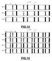
- the Figure 14 shows the case of two base stations BS A and BS B for which the RSI intervals are superimposed. It is said that there is a conflict between the base stations BS A and BS B. In this case, the network can manage this situation in several ways.
- each mobile station can detect at least two base stations whose reinforced synchronization intervals do not coincide with that of its dominant base station, then it can determine its position. This situation is illustrated in Figure 15. The network can decide then to do nothing since all the mobile stations can be located. If, on the other hand, as illustrated in Figure 14, the mobile stations do not have at least two conflict-free base stations to locate themselves, or if it is desired that the mobile stations should have more than two conflict-free base stations to locate themselves, then it must be ascertained that the RSI intervals of two mobile stations are not systematically overlapping. To do this, one of the following methods must be applied.
- a first method consists in taking instants of occurrence of the RSI intervals that are pseudo-random.
- ⁇ T n is a sequence of pseudo-random time gaps corresponding to integers ⁇ T n /T TS of time slots, these numbers ⁇ T n /T TS being pseudo-random with equiproblable values in ⁇ 0, 1, ..., ( ⁇ T max /T TS )-1 ⁇ and where ⁇ T max is a maximum spacing, such that ⁇ T n /T TS is an integer, smaller than or equal to T/T TS and greater than 1.
- the instant of occurrence T n corresponding to the beginning of the RSI interval is fixed with respect to an instant t 0 + n ⁇ T of periodic reference according to the period of occurrence T, said instant of occurrence T n being shifted by a time gap ⁇ T n varying pseudo-randomly at each period of occurrence with respect to said reference instant.
- ⁇ T n /T TS is generated according to a law common to all base stations and known to the mobile stations, its initialization parameters being transmitted with the parameters of the RSI string. Such laws are described for example in William H. Press and al. "Numerical Recipes in C", second edition, ISBN 0-521-43108-5, section 7.1.
- the advantage of using a pseudo-random law is that the mean period of occurrence of the RSI intervals, which is equal to the period of occurrence T, can be the same for all the base stations.
- Another advantage relates to the fact that the network periodically broadcasts certain items of system information that the mobile stations need in order to know the configuration of the cell. If the system information broadcasting period is the same as the period of occurrence of the RSI interval then, when there are no pseudo-random instants of occurrence, it will always be the same system information whose reception is disturbed by the presence of the additional synchronization signal. Thus, when there are no pseudo-random instants of occurrence, the system information broadcasting periods and the periods of occurrence of RSI intervals cannot be selected independently. This makes the system more difficult to configure.
- ⁇ S n is a sequence of pseudo-random numbers with equiprobable values in ⁇ 0, 1, ..., ⁇ S max -1 ⁇ , and ⁇ S max is an integer number smaller than or equal to T/ ⁇ ' and greater than or equal to 1.
- a second method to ensure that the RSI intervals of two base stations do not overlap systematically consists in defining different periods of occurrence for each base station.
- two neighbouring cells A and B have periods of occurrence with respective RSI intervals T A and T B , and that the gap between T A and T B is greater than D, then an overlapping of two RSI intervals will always be followed by a non-overlapping. This is illustrated in Figure 16.
- a first base station may set up periods of silence that are simultaneous with the RSI intervals of a second base station, it is necessary that the network should know the instants of occurrence of these RSI intervals in the time base of the first base station.
- a first method based on measurements of synchronization made at the time of the handovers has already been described.
- a second method is described. Like the first method, this second method does not require that the base stations should be synchronized with one another.
- the synchronization of a network is a complex task.
- Each base station produces an RSI string according to its own time base, which may drift with respect to those of the other base stations.
- Each base station is informed of the RSI string parameters of the base stations of the neighbouring cells by a base station controller.
- This controller is connected to the base stations by a typical wire link. If the base stations of two neighbouring cells are controlled by two different base station controllers, these controllers can send each other the RSI string parameters of the base stations that they control by a typical wire link.
- Each base station is provided with a radio receiver similar to that of a mobile station through which it can detect the instants of occurrence T n of the RSI intervals of the other base stations. The detection is made in the same synchronization steps as those done by the mobile station.
- the first base station detects the instant of occurrence T n of the RSI interval of the second base station, it deduces the value of t 0 therefrom in one of the following equations depending on the embodiment:
- the first base station can then determine the instants of occurrence of all the RSI intervals of the second base station.
- the values of t 0 and t n are herein expressed in the time base of the first base station.
- the first base station can then foresee the instant of occurrence of each RSI interval of the second base station, and interrupt its transmission simultaneously if that is necessary.
- the first base station makes a new measurement of the value of t 0 so as to compensate for the drift between the respective time bases of the two base stations considered. It should be noted that, in this method, it is possible to define a parameter T p of configuration of the first base station which is the propagation time from the second to the first base station.
- the first base station deducts T p from the starting instant estimated at the reception of the RSI interval numbered n of the second base station.
- the parameter T p is taken to be equal to zero.
- the second method that has just been explained may be used in combination with the first method that has already been described. It must also be noted that the results given by this second method are all the more satisfactory as periods of silence are set up by the first base station simultaneously with RSI intervals of the second base station. Thus, the measurement of synchronization made by the first base station is not disturbed, during the periods of silence, by the signals that it sends.
- a third method does not need the periods of silence. It is enough for the second base station to send a synchronization signal to the first base station on a physical channel other than the one used by the UMTS-FDD system, for example on a wire link. This physical channel must have a constant transmission time known to the first base station in the form of a parameter T p .
- the synchronization signal is used by the first base station to measure the gap between its time base and that of the second base station.
- the base station considered is equipped with decision-making means to determine the base stations of neighbouring cells for which it sets up a period of silence and/or for which it exceptionally omits to prepare such a period. This improvement gives a better trade-off between the positioning delay due to the omission of the period of silence and the disturbance generated by periods of silence that are too close to each other in time.
- the dominant base station takes the decision not to prepare a period of silence for all the neighbouring cells for each of the time intervals, known as decision intervals, of a sequence of periodic time intervals, for example for the sequence of the radio frames. This decision is made when the proportion of decision intervals intersecting one period of silence is higher than a threshold value of percentage, for example 20%.
- the dominant base station selects those base stations for which a period of silence is omitted. For example, the selection is made by means of a counter for each of the base stations of neighbouring cells. Whenever the dominant base station decides to set up a period of silence for a base station of a neighbouring cell, it resets the associated counter and, whenever it omits to set up a period of silence, it increments the counter.
- the dominant base station When the dominant base station makes the decision not to set up a period of silence for all the base stations of the neighbouring cells with an RSI interval that intersects the current decision interval, it selects the base stations by starting with those whose counter value is the lowest and does so until the proportion of the decision interval covered by the periods of silence passes below the threshold value of percentage.
- a first method consists in selecting one of them randomly.
- a second method consists in trying out all the possible selections, in the rising order of associated counters, and bringing the proportion of the decision interval covered by the periods of silence of the non-selected base stations below the threshold value of percentage.
- a coincident station In the event of conflict, i.e. when an RSI interval of a base station of a neighbouring cell, called a coincident station, coincides appreciably with an RSI interval of the dominant base station, the latter does not set up any period of silence for the coincident base station.
- the counter associated with said coincident station is incremented.
- the dominant base station, for each decision interval applies the same method of decision and selection in limiting itself to the base stations of neighbouring cells that are not coincident for the decision interval considered.
Landscapes
- Engineering & Computer Science (AREA)
- Computer Networks & Wireless Communication (AREA)
- Signal Processing (AREA)
- Mobile Radio Communication Systems (AREA)
- Synchronisation In Digital Transmission Systems (AREA)
- Time-Division Multiplex Systems (AREA)
Applications Claiming Priority (2)
| Application Number | Priority Date | Filing Date | Title |
|---|---|---|---|
| FR0006531 | 2000-05-23 | ||
| FR0006531A FR2809554B1 (fr) | 2000-05-23 | 2000-05-23 | Procede de synchronisation d'au moins une station mobile dans un reseau de telecommunication mobile ayant une structure de canal de synchronisation modifiee |
Publications (2)
| Publication Number | Publication Date |
|---|---|
| EP1164723A2 true EP1164723A2 (fr) | 2001-12-19 |
| EP1164723A3 EP1164723A3 (fr) | 2003-01-02 |
Family
ID=8850489
Family Applications (1)
| Application Number | Title | Priority Date | Filing Date |
|---|---|---|---|
| EP01460036A Withdrawn EP1164723A3 (fr) | 2000-05-23 | 2001-05-17 | Procédé de synchronisation d'au moins une station mobile dans un réseau de télécommunication mobile ayant une structure de canal de synchronisation modifiée |
Country Status (5)
| Country | Link |
|---|---|
| US (1) | US20020021718A1 (fr) |
| EP (1) | EP1164723A3 (fr) |
| JP (1) | JP2002016575A (fr) |
| CN (1) | CN1325196A (fr) |
| FR (1) | FR2809554B1 (fr) |
Cited By (7)
| Publication number | Priority date | Publication date | Assignee | Title |
|---|---|---|---|---|
| GB2379581A (en) * | 2001-09-11 | 2003-03-12 | Nec Technologies | Compensation for signal time of arrival variation in UMTS handset |
| FR2851876A1 (fr) * | 2003-02-28 | 2004-09-03 | Nec Technologies Uk Ltd | Procede d'optimisation de la recherche de cellule dans un reseau de telecommunication cdma |
| FR2851875A1 (fr) * | 2003-02-28 | 2004-09-03 | Nec Technologies Uk Ltd | Procede d'optimisation de la recherche de cellule dans un reseau de telecommunication cdma |
| KR100736650B1 (ko) | 2005-11-30 | 2007-07-09 | 후지쯔 가부시끼가이샤 | 무선 기지국 및 무선 통신 방법 |
| RU2469498C2 (ru) * | 2007-05-01 | 2012-12-10 | Нтт Досомо, Инк. | Базовая станция, мобильная станция и способ передачи канала синхронизации |
| WO2015160615A3 (fr) * | 2014-04-14 | 2016-02-04 | Qualcomm Incorporated | Capture de pss et de sss avec une chaîne de réception de réseau local sans fil |
| US9686705B2 (en) | 2014-04-14 | 2017-06-20 | Qualcomm Incorporated | Capture of PSS and SSS with wireless local area network receive chain |
Families Citing this family (29)
| Publication number | Priority date | Publication date | Assignee | Title |
|---|---|---|---|---|
| EP1255363B1 (fr) * | 2001-05-04 | 2007-06-27 | Lucent Technologies Inc. | Système de télécommunication sans fil et procédé pour transmission asymétrique des données |
| WO2003017689A1 (fr) | 2001-08-14 | 2003-02-27 | Flarion Technologies, Inc. | Procedes et appareil de connectivite de reseau radio |
| EP1318625A1 (fr) * | 2001-12-10 | 2003-06-11 | Alcatel | Procédé et appareil pour recuperer une fréquence inconnue dans une système de télécommunication digitale cellulaire |
| KR20040017909A (ko) * | 2002-08-22 | 2004-03-02 | 광주과학기술원 | 이중화 통신시스템에 적용되는 얽힌 주파수 분할 이중화방법 |
| US7586864B2 (en) | 2003-09-30 | 2009-09-08 | Sharp Kabushiki Kaisha | Communication system, base station, terminal, communication device, communication management method, control program, and computer-readable recording medium containing the same |
| AU2003290478A1 (en) * | 2003-12-18 | 2005-07-05 | Telefonaktiebolaget Lm Ericsson (Publ) | A method and apparatus for determining the content of bursts to be transmitted from a base station |
| US20050238060A1 (en) * | 2004-04-23 | 2005-10-27 | Kuntz Thomas L | Synchronizing to GSM RF downlink signal frame timing |
| EP1760942A4 (fr) * | 2004-06-25 | 2008-10-08 | Mitsubishi Electric Corp | Méthode de synchronisation du temps entre des stations de base, dispositif maître de synchronisation, et station de base |
| MX2007012122A (es) * | 2005-03-28 | 2007-11-20 | Thomson Licensing | Busqueda de celda mejorada para condiciones de transferencia. |
| FR2895200B1 (fr) * | 2005-12-20 | 2008-02-22 | Silicon Lab Inc | Procede d'acquisition d'un burst de correction de frequence par un dispositif de radiocommunication, et dispositif de radiocommunication correspondant. |
| US20070282492A1 (en) * | 2006-05-31 | 2007-12-06 | Sensis Corporation | Method and system of managing data transmissions from broadcast-equipped targets |
| JP5386351B2 (ja) * | 2007-04-27 | 2014-01-15 | パナソニック株式会社 | 移動通信端末及び通信装置並びに移動通信端末のハンドオーバ方法 |
| US7920598B2 (en) * | 2007-05-25 | 2011-04-05 | Qualcomm Incorporated | Scrambling methods for synchronization channels |
| US8249616B2 (en) * | 2007-08-23 | 2012-08-21 | Texas Instruments Incorporated | Satellite (GPS) assisted clock apparatus, circuits, systems and processes for cellular terminals on asynchronous networks |
| US20090097452A1 (en) * | 2007-10-12 | 2009-04-16 | Qualcomm Incorporated | Femto cell synchronization and pilot search methodology |
| US8031693B2 (en) * | 2007-11-20 | 2011-10-04 | Research In Motion Limited | System and method for timing synchronization |
| US8335176B2 (en) * | 2008-04-07 | 2012-12-18 | Qualcomm Incorporated | Transmission of overhead channels with timing offset and blanking |
| CN101621840A (zh) * | 2008-07-03 | 2010-01-06 | 中兴通讯股份有限公司 | 系统消息的发送方法 |
| FR2942097A1 (fr) * | 2009-02-06 | 2010-08-13 | Thomson Licensing | Procede d'emission dans un reseau sans fil et procede de reception correspondant |
| CN102037772B (zh) * | 2009-12-07 | 2015-06-03 | 高通股份有限公司 | 在td-scdma上行链路同步中提高同步移位命令传输效率的方法和装置 |
| JP5459783B2 (ja) * | 2010-03-19 | 2014-04-02 | Kddi株式会社 | 無線端末 |
| US9414336B2 (en) | 2010-05-12 | 2016-08-09 | Blackberry Limited | System and method for defining a burst period |
| EP2511980B1 (fr) | 2011-04-11 | 2013-08-28 | Tecom Co., Ltd. | Antenne imprimée de bande large |
| CN109005019B (zh) * | 2014-12-31 | 2020-01-03 | 华为技术有限公司 | 信号发送和检测装置、系统及方法 |
| US10122559B2 (en) | 2016-03-21 | 2018-11-06 | Qualcomm Incorporated | Uplink channel quality measurement using a subframe with high-intensity reference signal bursts |
| JP2017183987A (ja) * | 2016-03-30 | 2017-10-05 | パナソニックIpマネジメント株式会社 | 端末装置 |
| US11121794B2 (en) * | 2016-10-17 | 2021-09-14 | Qualcomm Incorporated | Configurable synchronization in next generation wireless networks |
| EP3399809B1 (fr) * | 2017-05-02 | 2024-07-17 | Fujitsu Limited | Signaux de synchronisation en 5g |
| CN108809878B (zh) * | 2017-05-04 | 2024-05-17 | 华为技术有限公司 | 同步信号的发送方法、同步信号的接收方法及相关设备 |
Family Cites Families (10)
| Publication number | Priority date | Publication date | Assignee | Title |
|---|---|---|---|---|
| FI91345C (fi) * | 1992-06-24 | 1994-06-10 | Nokia Mobile Phones Ltd | Menetelmä kanavanvaihdon tehostamiseksi |
| GB2297460B (en) * | 1995-01-28 | 1999-05-26 | Motorola Ltd | Communications system and a method therefor |
| US5978679A (en) * | 1996-02-23 | 1999-11-02 | Qualcomm Inc. | Coexisting GSM and CDMA wireless telecommunications networks |
| US5945949A (en) * | 1997-01-13 | 1999-08-31 | Lucent Technologies Inc. | Mobile station position determination in a wireless communication system |
| FR2761224B1 (fr) * | 1997-03-20 | 2001-10-05 | Alsthom Cge Alkatel | Procede d'enregistrement d'au moins une station mobile bimode aupres d'une station de base domestique associee |
| DE19737124A1 (de) * | 1997-08-26 | 1999-03-18 | Siemens Ag | Verfahren und Kommunikationssystem zur drahtlosen Übertragung von Informationen zwischen einem mobilen Endgerät und einer Feststation |
| SE9800988L (sv) * | 1998-03-24 | 1999-09-25 | Ericsson Telefon Ab L M | Sätt och anordning vid cellbaserat kommunikationssystem |
| CN1153380C (zh) * | 1998-04-28 | 2004-06-09 | 西门子公司 | 用中断阶段法进行数据传输 |
| FR2778055B1 (fr) * | 1998-04-28 | 2000-05-26 | Alsthom Cge Alcatel | Procede de transmission dans un reseau radiotelephonique umts,permettant de preparer un saut vers une cellule gsm pendant une communication dans une cellule umts |
| DE60044928D1 (de) * | 1999-04-29 | 2010-10-21 | Samsung Electronics Co Ltd | Gerät und verfahren für synkronisation von kanälen in einem breitband w-cdma kommunikationssystem |
-
2000
- 2000-05-23 FR FR0006531A patent/FR2809554B1/fr not_active Expired - Fee Related
-
2001
- 2001-05-17 US US09/858,502 patent/US20020021718A1/en not_active Abandoned
- 2001-05-17 EP EP01460036A patent/EP1164723A3/fr not_active Withdrawn
- 2001-05-22 JP JP2001152998A patent/JP2002016575A/ja active Pending
- 2001-05-23 CN CN01117000A patent/CN1325196A/zh active Pending
Cited By (9)
| Publication number | Priority date | Publication date | Assignee | Title |
|---|---|---|---|---|
| GB2379581A (en) * | 2001-09-11 | 2003-03-12 | Nec Technologies | Compensation for signal time of arrival variation in UMTS handset |
| GB2379581B (en) * | 2001-09-11 | 2005-08-31 | Nec Technologies | Apparatus and method of compensation for signal time-of-arrival variation in a UMTS handset |
| FR2851876A1 (fr) * | 2003-02-28 | 2004-09-03 | Nec Technologies Uk Ltd | Procede d'optimisation de la recherche de cellule dans un reseau de telecommunication cdma |
| FR2851875A1 (fr) * | 2003-02-28 | 2004-09-03 | Nec Technologies Uk Ltd | Procede d'optimisation de la recherche de cellule dans un reseau de telecommunication cdma |
| KR100736650B1 (ko) | 2005-11-30 | 2007-07-09 | 후지쯔 가부시끼가이샤 | 무선 기지국 및 무선 통신 방법 |
| RU2469498C2 (ru) * | 2007-05-01 | 2012-12-10 | Нтт Досомо, Инк. | Базовая станция, мобильная станция и способ передачи канала синхронизации |
| WO2015160615A3 (fr) * | 2014-04-14 | 2016-02-04 | Qualcomm Incorporated | Capture de pss et de sss avec une chaîne de réception de réseau local sans fil |
| US9686705B2 (en) | 2014-04-14 | 2017-06-20 | Qualcomm Incorporated | Capture of PSS and SSS with wireless local area network receive chain |
| US9699682B2 (en) | 2014-04-14 | 2017-07-04 | Qualcomm Incorporated | Capture of PSS and SSS with wireless local area network receive chain |
Also Published As
| Publication number | Publication date |
|---|---|
| EP1164723A3 (fr) | 2003-01-02 |
| JP2002016575A (ja) | 2002-01-18 |
| CN1325196A (zh) | 2001-12-05 |
| FR2809554B1 (fr) | 2002-08-16 |
| FR2809554A1 (fr) | 2001-11-30 |
| US20020021718A1 (en) | 2002-02-21 |
Similar Documents
| Publication | Publication Date | Title |
|---|---|---|
| EP1164723A2 (fr) | Procédé de synchronisation d'au moins une station mobile dans un réseau de télécommunication mobile ayant une structure de canal de synchronisation modifiée | |
| US20220353833A1 (en) | Method and device for transmitting and receiving synchronization signal of device-to-device communication terminal in wireless communication system | |
| US11032785B2 (en) | Method and device for transmitting/receiving sync signal of device-to-device communication terminal in wireless communication system | |
| JP6980899B2 (ja) | ランダム接続過程を行う方法及びそのための装置 | |
| EP0990317B1 (fr) | Commande d'horloge d'intervals temporels de transmission | |
| US12082223B2 (en) | Methods and apparatuses for resource allocation in a telecommunications network | |
| US6223040B1 (en) | Method and a system in a cellular network | |
| RU2742208C1 (ru) | Конкретные шаблоны перескока для повторяющейся передачи и приема данных и способы для их формирования | |
| CN1314747B (zh) | 在无线通信系统中进行上行链路通信的方法和设备 | |
| CN106658584B (zh) | 信号发送与接收和干扰测量的方法及设备 | |
| RU2595269C2 (ru) | Способ и система телекоммуникаций | |
| EP3269169B1 (fr) | Système et procédé pour un canal de poursuite | |
| EP0922373B1 (fr) | Communication radio avec transmission de balises avec gigue | |
| CN100468992C (zh) | 用于在一个自组织无线电通信系统中分散同步的方法 | |
| JP4574173B2 (ja) | 通信方法 | |
| JP2019517201A (ja) | 制御チャネルのためのリソースの設定情報を伝送する方法および装置、アップリンクdrsのためのリソースの設定情報を伝送する方法および装置、サブフレーム/スロットのタイプを指示する指示子を伝送する方法および装置、そしてダウンリンクシンボルの個数を伝送する方法および装置 | |
| US20080240072A1 (en) | Method and Apparatus For Synchronization of Base Stations in a Broadband Wireless Access System | |
| SE518132C2 (sv) | Metod och anordning för synkronisering av kombinerade mottagare och sändare i ett cellulärt system | |
| KR100770231B1 (ko) | 시분할 이중화 cdma 시스템에서의 이동 장치의 동기화방법 | |
| CN107205262B (zh) | 一种基于无线自组织网络的数据传输方法及装置 | |
| RU2213419C2 (ru) | Способ и система радиосвязи для синхронизации абонентских станций | |
| JP2000232689A (ja) | 無線網 | |
| WO2001099452A1 (fr) | Dispositif de station de base et procede d'attribution de canaux | |
| EP1092332B1 (fr) | Procede servant a communiquer des donnees au moyen de signaux radio et appareil de radiocommunications | |
| US7269150B2 (en) | Method for transmitting signaling |
Legal Events
| Date | Code | Title | Description |
|---|---|---|---|
| PUAI | Public reference made under article 153(3) epc to a published international application that has entered the european phase |
Free format text: ORIGINAL CODE: 0009012 |
|
| 17P | Request for examination filed |
Effective date: 20010606 |
|
| AK | Designated contracting states |
Kind code of ref document: A2 Designated state(s): AT BE CH CY DE DK ES FI FR GB GR IE IT LI LU MC NL PT SE TR |
|
| AX | Request for extension of the european patent |
Free format text: AL;LT;LV;MK;RO;SI |
|
| PUAL | Search report despatched |
Free format text: ORIGINAL CODE: 0009013 |
|
| AK | Designated contracting states |
Kind code of ref document: A3 Designated state(s): AT BE CH CY DE DK ES FI FR GB GR IE IT LI LU MC NL PT SE TR |
|
| AX | Request for extension of the european patent |
Free format text: AL;LT;LV;MK;RO;SI |
|
| RAP1 | Party data changed (applicant data changed or rights of an application transferred) |
Owner name: MELCO MOBILE COMMUNICATIONS EUROPE (SA) |
|
| AKX | Designation fees paid |
Designated state(s): DE FR GB |
|
| 17Q | First examination report despatched |
Effective date: 20040116 |
|
| STAA | Information on the status of an ep patent application or granted ep patent |
Free format text: STATUS: THE APPLICATION IS DEEMED TO BE WITHDRAWN |
|
| 18D | Application deemed to be withdrawn |
Effective date: 20040527 |