EP1165150B1 - Cassette pour appareil de sterilisation sous vide et a la vapeur - Google Patents
Cassette pour appareil de sterilisation sous vide et a la vapeur Download PDFInfo
- Publication number
- EP1165150B1 EP1165150B1 EP00916719A EP00916719A EP1165150B1 EP 1165150 B1 EP1165150 B1 EP 1165150B1 EP 00916719 A EP00916719 A EP 00916719A EP 00916719 A EP00916719 A EP 00916719A EP 1165150 B1 EP1165150 B1 EP 1165150B1
- Authority
- EP
- European Patent Office
- Prior art keywords
- cassette
- seal
- sterilization
- lid
- tray
- Prior art date
- Legal status (The legal status is an assumption and is not a legal conclusion. Google has not performed a legal analysis and makes no representation as to the accuracy of the status listed.)
- Expired - Lifetime
Links
Images

Classifications
-
- A—HUMAN NECESSITIES
- A61—MEDICAL OR VETERINARY SCIENCE; HYGIENE
- A61L—METHODS OR APPARATUS FOR STERILISING MATERIALS OR OBJECTS IN GENERAL; DISINFECTION, STERILISATION OR DEODORISATION OF AIR; CHEMICAL ASPECTS OF BANDAGES, DRESSINGS, ABSORBENT PADS OR SURGICAL ARTICLES; MATERIALS FOR BANDAGES, DRESSINGS, ABSORBENT PADS OR SURGICAL ARTICLES
- A61L2/00—Disinfection or sterilisation of materials or objects, in general; Accessories therefor
- A61L2/02—Disinfection or sterilisation of materials or objects, in general; Accessories therefor using physical processes
- A61L2/04—Heat
- A61L2/06—Hot gas
- A61L2/07—Steam
-
- A—HUMAN NECESSITIES
- A61—MEDICAL OR VETERINARY SCIENCE; HYGIENE
- A61L—METHODS OR APPARATUS FOR STERILISING MATERIALS OR OBJECTS IN GENERAL; DISINFECTION, STERILISATION OR DEODORISATION OF AIR; CHEMICAL ASPECTS OF BANDAGES, DRESSINGS, ABSORBENT PADS OR SURGICAL ARTICLES; MATERIALS FOR BANDAGES, DRESSINGS, ABSORBENT PADS OR SURGICAL ARTICLES
- A61L2/00—Disinfection or sterilisation of materials or objects, in general; Accessories therefor
- A61L2/02—Disinfection or sterilisation of materials or objects, in general; Accessories therefor using physical processes
- A61L2/08—Radiation
-
- A—HUMAN NECESSITIES
- A61—MEDICAL OR VETERINARY SCIENCE; HYGIENE
- A61L—METHODS OR APPARATUS FOR STERILISING MATERIALS OR OBJECTS IN GENERAL; DISINFECTION, STERILISATION OR DEODORISATION OF AIR; CHEMICAL ASPECTS OF BANDAGES, DRESSINGS, ABSORBENT PADS OR SURGICAL ARTICLES; MATERIALS FOR BANDAGES, DRESSINGS, ABSORBENT PADS OR SURGICAL ARTICLES
- A61L2/00—Disinfection or sterilisation of materials or objects, in general; Accessories therefor
- A61L2/24—Apparatus using programmed or automatic operation
-
- A—HUMAN NECESSITIES
- A61—MEDICAL OR VETERINARY SCIENCE; HYGIENE
- A61L—METHODS OR APPARATUS FOR STERILISING MATERIALS OR OBJECTS IN GENERAL; DISINFECTION, STERILISATION OR DEODORISATION OF AIR; CHEMICAL ASPECTS OF BANDAGES, DRESSINGS, ABSORBENT PADS OR SURGICAL ARTICLES; MATERIALS FOR BANDAGES, DRESSINGS, ABSORBENT PADS OR SURGICAL ARTICLES
- A61L2/00—Disinfection or sterilisation of materials or objects, in general; Accessories therefor
- A61L2/26—Accessories
-
- A—HUMAN NECESSITIES
- A61—MEDICAL OR VETERINARY SCIENCE; HYGIENE
- A61L—METHODS OR APPARATUS FOR STERILISING MATERIALS OR OBJECTS IN GENERAL; DISINFECTION, STERILISATION OR DEODORISATION OF AIR; CHEMICAL ASPECTS OF BANDAGES, DRESSINGS, ABSORBENT PADS OR SURGICAL ARTICLES; MATERIALS FOR BANDAGES, DRESSINGS, ABSORBENT PADS OR SURGICAL ARTICLES
- A61L2103/00—Materials or objects being the target of disinfection or sterilisation
- A61L2103/15—Laboratory, medical or dentistry appliances, e.g. catheters or sharps
-
- A—HUMAN NECESSITIES
- A61—MEDICAL OR VETERINARY SCIENCE; HYGIENE
- A61L—METHODS OR APPARATUS FOR STERILISING MATERIALS OR OBJECTS IN GENERAL; DISINFECTION, STERILISATION OR DEODORISATION OF AIR; CHEMICAL ASPECTS OF BANDAGES, DRESSINGS, ABSORBENT PADS OR SURGICAL ARTICLES; MATERIALS FOR BANDAGES, DRESSINGS, ABSORBENT PADS OR SURGICAL ARTICLES
- A61L2202/00—Aspects relating to methods or apparatus for disinfecting or sterilising materials or objects
- A61L2202/10—Apparatus features
- A61L2202/12—Apparatus for isolating biocidal substances from the environment
- A61L2202/122—Chambers for sterilisation
-
- A—HUMAN NECESSITIES
- A61—MEDICAL OR VETERINARY SCIENCE; HYGIENE
- A61L—METHODS OR APPARATUS FOR STERILISING MATERIALS OR OBJECTS IN GENERAL; DISINFECTION, STERILISATION OR DEODORISATION OF AIR; CHEMICAL ASPECTS OF BANDAGES, DRESSINGS, ABSORBENT PADS OR SURGICAL ARTICLES; MATERIALS FOR BANDAGES, DRESSINGS, ABSORBENT PADS OR SURGICAL ARTICLES
- A61L2202/00—Aspects relating to methods or apparatus for disinfecting or sterilising materials or objects
- A61L2202/10—Apparatus features
- A61L2202/14—Means for controlling sterilisation processes, data processing, presentation and storage means, e.g. sensors, controllers, programs
-
- Y—GENERAL TAGGING OF NEW TECHNOLOGICAL DEVELOPMENTS; GENERAL TAGGING OF CROSS-SECTIONAL TECHNOLOGIES SPANNING OVER SEVERAL SECTIONS OF THE IPC; TECHNICAL SUBJECTS COVERED BY FORMER USPC CROSS-REFERENCE ART COLLECTIONS [XRACs] AND DIGESTS
- Y10—TECHNICAL SUBJECTS COVERED BY FORMER USPC
- Y10T—TECHNICAL SUBJECTS COVERED BY FORMER US CLASSIFICATION
- Y10T137/00—Fluid handling
- Y10T137/9029—With coupling
Definitions
- the present invention is directed to a cassette adapted for sterilizing instruments using both vacuum and steam, and in particular to a cassette having a seal allowing the cassette to operate between conditions of vacuum and pressure, and inlet and outlet couplings that facilitate sterilization as well as maintain sterility and vacuum conditions after sterilization.
- cassette-using apparatus taught by the Newman patents offer significant advantages over conventional steam purging/sterilizing autoclave techniques, these cassettes are not adapted to use vacuum as part of the steam sterilization process. In addition, these cassettes are not designed for storing sterilized instruments.
- the present invention responds to these needs by providing a cassette for use in a sterilization method and apparatus employing both vacuum and steam and one that is adapted to store sterilized instruments over time.
- Another object of the present invention is a cassette designed to maintain sterile conditions for storage of steam-sterilized instruments.
- Yet another object of the present invention is a cassette having a seal that permits the cassette to function under conditions of pressure and vacuum during a sterilization method.
- the present invention provides a sterilization cassette comprising a tray having at least an inlet opening and an outlet opening for connection to probes of a steam sterilization apparatus that is adapted to sterilize instruments supported by the tray.
- the cassette has a lid hinged to the tray, the lid including a seal arranged along a lid periphery.
- the lid is adapted to move between an open position, a closed position, and an intermediate position, the lid, the seal, and the tray forming a sealed chamber for sterilization when the lid is in the closed and intermediate positions.
- Each of the inlet and the outlet openings has a coupling located therein to permit communication between the steam sterilization apparatus and the sterilization chamber.
- the seal comprises a continuous seal body running along a periphery of the lid, with first and second lips extending from the seal body and being pivotally linked thereto.
- a third lip extends from the seal body and is spaced from the second lip to form a channel therebetween. The first and second lips in concert with the channel provide sealing in the intermediate position and the first, second, and third lips provide sealing in the closed position.
- the outlet has at least one opening positioned in the chamber, the at least one opening spaced from a bottom of the tray.
- a duct can be attached to the outlet at the one end thereof, with an opposite end of the duct positioned adjacent to the bottom of the tray to provide a channel for collection of condensate during steam sterilization of the instruments.
- each of the inlet and the outlet further comprises a coupling body and seal assembly movably mounted through a wall of the tray to accommodate self alignment between probes of the sterilization apparatus and the coupling body while maintaining a seal between the coupling body and the wall.
- Each inlet and outlet coupling may have a first valve to permit communication between the steam sterilization apparatus and the sterilization chamber, and a second valve may be provided as part of the cassette to release excess pressure in the sterilization chamber, the first and second valves also sealing the sterilization chamber for storage of sterilized instruments.
- the cassette also employs a unique seal to maintain sterility when the cassette is removed.
- one end of the coupling body is arranged outside of the sterilization chamber, and a second end is arranged within the sterilization chamber.
- the one end has a seal device on a peripheral surface thereof.
- the seal device is spaced from the wall such that a seal is formed between the peripheral surface and a probe surface prior to opening or closing of the first valve to seal the sterilization chamber from ambient.
- the cassette employs a dual valve coupling arrangement, whereby the first and second valves are arranged in the coupling body.
- the first valve is biased in a closed position, and adapted to be opened when a force is applied to a valve face against the bias.
- the second valve is biased in a closed position and movable to an open position upon application of a force applied from within the sterilization chamber.
- the bias can be provided by a spring arranged between the two valves.
- the first valve may have a bore therein that provides communication between the first opening and the second valve so that when the sterilization chamber is under a vacuum for storage, the spring bias and atmospheric pressure maintains each of the first valve and the second valve in the closed position.
- the invention also entails the flexible seal for a sterilization cassette as well as a method of using the cassette as part of a sterilization process employing steam and vacuum.
- the method of steam sterilizing instruments comprises the steps of placing instruments in the sterilization chamber and connecting the inlet and outlet thereof to probes of a steam sterilization apparatus. The instruments are subjected to a steam sterilization cycle using pressure and vacuum conditions. The cassette is then removed upon completion of the steam sterilization cycle and is either stored with the instruments in the cassette under vacuum conditions, or the instruments are removed from the cassette for use.
- a dual valve coupling that could be employed in the cassette is also provided.
- the inventive cassette offers significant advantages in the field of sterilizing instruments such as those used in the medical and dental fields.
- the cassette can be used in methods and apparatus that employ vacuum conditions to remove air from the cassette prior to steam sterilization as well as the pressure conditions commonly encountered during steam sterilization.
- the inventive cassette permits the sterilized instruments to be stored within the cassette until ready for use.
- the cassette itself functions not only as a sterilizing device but also a storage device for sterilized instruments.
- the cassette's design also maintains a sterile atmosphere within the cassette interior when being removed from the sterilizing apparatus.
- the inventive cassette is adapted for use with an apparatus and method that uses both vacuum and steam as part of the sterilization. More particularly, the cassette has a lid and seal assembly which moves between two positions with respect to a tray. The tray has inlet and outlet couplings which facilitate subjecting the interior of the cassette to vacuum and steam conditions as part of the sterilization process.
- the first position of the lid is a closed position whereby the cassette interior is sealed from the outside when under vacuum or when sterile, either during the sterilization process or in a storage mode.
- the second position of the lid occurs when the interior is pressurized and the lid is raised with respect to the tray.
- the seal still isolates the cassette interior from the outside even though the lid is not in the first or closed position.
- the inlet and outlet couplings are configured to assure that once the instruments are sterilized, cassette removal from the sterilizing apparatus does not compromise the sterile cassette interior.
- This configuration utilizes valves and seals in each coupling, one set of seals positioned on the cassette exterior.
- the exterior seals isolate the interior of the cassette when the couplings are being disengaged from steam-supplying or evacuating probes of the sterilization apparatus.
- the exterior seals continue to isolate the sterile cassette interior from the outside until valves in the couplings close for sealing purposes.
- the inlet and outlet couplings also employ a pressure relief valve that allows release of unwanted pressure inside the cassette interior.
- the pressure relief valve also functions in concert with the other valve in the coupling to maintain vacuum conditions in the cassette interior once the sterilization process is complete. By maintaining such conditions, the instruments that have been sterilized can be stored for an extended period of time within the cassette. Thus, instruments can be sterilized ahead of time and stored until needed.
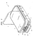
- FIG. 1 shows a preferred cassette embodiment 10 for storage of dental instruments, medical instruments, or the like.
- the cassette is comprised of two halves: a lower half hereafter referred to as “cassette tray” 1 and an upper half hereafter referred to as “cassette lid” 3.
- the cassette tray 1 is a container with a bottom and walls into which the instruments to be sterilized are placed and which remains stationary inside a sterilization apparatus throughout the entire sterilization cycle.
- the cassette 10 includes an auxiliary handle 5 shown in its carrying position and a front handle 7 shown in its resting position.
- a rear handle (not shown), which is of a similar design and construction to the front handle and which is located at the rear of the cassette, can also be realized.
- Both the cassette tray and the cassette lid are preferably constructed out of stainless steel or similar materials to facilitate heat transfer to the cassette contents during the sterilization cycle. Of course, other handle designs may be utilized to transport the cassette 10.
- One inventive aspect of the cassette 10 lies-in the fact that when used in conjunction with a sterilization apparatus and method that employs a structural chamber, hereafter referred to as an armature, the combined system is capable of withstanding both pressure and vacuum required for sterilization of dental and medical instruments. Yet at the same time, the lightweight cassette provides portability and sterile transport/storage of instruments.
- the preferred cassette embodiment functions under vacuum because the sterilization system draws a vacuum on both the cassette and the space created by the armature surrounding the cassette, resulting in a zero differential pressure between the cassette and the armature during all vacuum draws.
- the preferred cassette embodiment functions under pressure due to the fact that the cassette is transmitting most of the structural load to the structurally-superior armature during pressurization. Thus no undue stresses were exerted on the cassette itself during a sterilization cycle.
- This sterilization apparatus is disclosed in the Applicant's co-pending Canadian patent application no. 2,268,042.
- the cassette 10 is preferably constructed with reinforcing members or bumpers 6 on ends of both the tray 1 and the lid 3.
- the bumpers 6 provide additional structural support to the tray 1 and lid 3 in areas that are not in contact with the armature since these areas, unlike the top and bottom of the cassette, do not have additional support during the pressurization cycle of the sterilization process.
- the bumpers 6 are depicted as plates that are spot-welded or attached in other ways to the lid 3 and tray 1. Other forms of structural support could also be employed such as strengthening ribs in the walls of the lid and tray or the like.
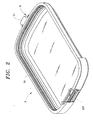
- the upside down cassette lid 3, as shown in Figure 2 is connected via a conventional hinge 9 to the cassette tray 1 and is capable of moving vertically up or down with respect to the cassette tray depending on the pressure inside the cassette.
- the hinge tab 11 fits within a complementary-sized slot 8 in a flange 12 in the tray 1, see Figure 5.
- a tight seal is formed between the cassette lid 3 and cassette tray 1 via an end-user replaceable, bi-directional seal gland 13 installed on the inner lining of the cassette lid 3.
- the seal 13 has a continuous form which surrounds the lid periphery.
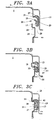
- Figure 3A shows a cross-section of the bi-directional seal 13, which consists of a continuous seal body 15, a first lip 17, a second lip 19, and a third lip 21.
- the first lip 17 and the second lip 19 are connected to the main body 15 via the seal pivot member 23.
- the seal body 15 rests in a channel 25 having opposing walls; the third lip 21 resting against one of the walls 27.
- the other wall 29 protects the first lip 17 as described below.
- the second lip 19 first comes into contact with the cassette tray surface 33, as shown in Figure 3B.
- the second lip 19 rotates upwards and outwards about the seal pivot member 23, causing the first lip 17 to rotate upwards and inwards until it comes into contact with the cassette tray wall 35 to form a first seal 37.
- Further travel of the cassette lid 3 towards the cassette tray 1 causes the second lip 19 to also come into contact with the cassette tray wall 35, forming a second seal 39.
- the third lip 21 comes into contact with the cassette tray surface 33 to form a third and final seal 41 (the closed position), as shown in Figure 3C.
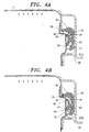
- the upward movement of the cassette lid 3 during pressurization also ensures good thermal contact between the stainless steel cassette lid 3 and the upper heating plate 44 situated in the armature (not shown), as well as between the stainless steel cassette tray 1 and the lower heating plate (also not shown). This facilitates the heat transfer from the heating plates to the cassette contents, thereby shortening the time it takes to bring the cassette contents to sterilization temperature.
- FIG. 5 Another aspect of the inventive cassette involves an inlet and an outlet to allow for ingress and egress of steam, air, and the like as part of the steam sterilization process.
- steam enters the cassette through a coupling in the cassette tray 1; hereafter referred to as the inlet coupling 45 and exits the cassette through another coupling of identical design in the cassette tray, hereafter referred to as the outlet coupling 47.
- the inlet and outlet couplings are mounted on the rear wall of the cassette tray as shown in Figure 5.
- the couplings 45 and 47 are characterized as inlet and outlets, depending on the particular sterilization cycle taking place, both couplings could function as inlets or outlets.
- each coupling 45 and 47 could be used as an outlet as described in Applicant's Canadian patent application mentioned above.
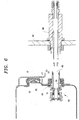
- FIG. 6 shows a preferred coupling embodiment and the preferred mating probe embodiment of a sterilization system.
- Each coupling is attached to the cassette tray by means of an O-ring seal 49 placed between a coupling flange 51 and an inner rear wall 53 of the cassette tray 1.
- a wave spring 55 or a compression spring of similar design and a threaded nut 57 are employed to fasten the coupling 45 to the tray 1. When the nut 57 is tightened on the coupling 45, it compresses the wave spring 55 and the O-ring seal 49, thereby creating a leak-free attachment.
- this arrangement permits slight movements of the couplings 45 and 47 with respect to the cassette tray to permit self alignment of the couplings to a probe 59 during the insertion of the cassette into the armature (not shown), while maintaining the leak-free attachment.
- the probe 59 is mounted in a wall 61 of the sterilization apparatus (not shown) and provides communication between the interior of the tray 1 and the various media and processing used as part of the sterilization apparatus and methodology.
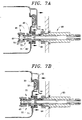
- Figure 7A shows the components of the coupling embodiment of Figure 6, including a coupling body 63, a coupling O-ring 64, a front-poppet valve 65, a front-poppet valve O-ring 67, a rear-poppet valve 69, a front-poppet face seal 71, rear-poppet face seal 73 and a compression spring 75.
- the compression spring 75 forces the front-poppet valve 65 against the front-poppet face seal 71, the rear-poppet valve 69 against the rear-poppet face seal 73, and the front-poppet valve O-ring 67 against the coupling body 63.
- This arrangement seals openings 77 in the coupling, thereby isolating the cassette contents from the outside.
- the coupling O-ring 64 first comes into contact with the inner surface 79 of each probe body 59, thereby creating a leak-free conduit between the cassette contents and the rest of the system as shown in Figure 7A. Further travel of the cassette 10 causes the tapered probe tip 81 to come into contact with the front poppet valve 65, thereby pushing it away from the front-poppet face seal 71 by compressing the compression spring 75. The inward movement of the front-poppet valve 65 in the coupling 45 also unblocks the openings 77 in the coupling body 63.
- cassette interior is then in communication with a sterilization system via the interior of the probe 59 for steam sterilization, purging, drying, and the like.
- the coupling 45 also serves as pressure relief device to allow proper closure of the cassette lid 3 and allow a pressurized cassette to be disengaged from the system in the event of a power failure and/or user intervention.
- the sealing is effective once the first lip 17 is in contact with the cassette tray wall 35, see Figure 3B.
- the air inside the cassette 10 will resist any further closure of the cassette lid 3.
- the compression spring 75 in the coupling 45 is designed to overcome a predetermined cassette pressure. When the cassette pressure exceeds the predetermined limit, the compression spring 75 will be compressed, thereby allowing the rear-poppet valve 69 to move away from the rear-poppet face seal 73, thus creating a pathway for the cassette pressure to escape.
- the pressure relief property of the coupling also applies in the event of an interruption in sterilization cycle where the cassette is pressurized and the removal of the cassette is deemed desirable.
- the pressure relief device can be provided as a separate valve in the cassette wall, or as part of the coupling as described above.
- the dual-poppet coupling design also permits sterile transport and storage of instruments in the cassette.
- the cassette is detached from the probes 59 and disengaged from the system.
- the front poppet valve 65 returns to its natural position of sealing the openings 77 in the coupling while the coupling O-ring 64 is still engaged with the probe body surface 79.
- the sterile environment in the cassette 10 is not compromised during cassette removal.
- the cassette contents Upon disengagement of the coupling O-ring 64 from the probe body surface 79, the cassette contents have already been sealed by the closing action of the valve 65 to avoid recontamination.
- the cassette As the stainless steel cassette is heated during the final drying phase of the sterilization cycle, the cassette is still warm to the touch when disengaging from the system. As the cassette cools down to ambient temperature, the volume of air inside the cassette decreases, resulting in a gradual build up of vacuum inside the cassette.
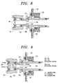
- FIG 9 shows how the dual-poppet coupling maintains the low vacuum created by the cooling of the cassette.
- the cassette pressure P2 is less than the ambient pressure P1.
- the front-poppet valve 65 has a center opening 91, the space between the front-and rear-poppet valves 93 also experiences pressure P1.
- the surface area of the rear-poppet valve facing the inside of the cassette, A2 is also smaller than the surface area of the rear-poppet valve facing the outside of the cassette, A1.
- the front-poppet valve 65 is pressed against the front-poppet face seal 71 and the front-poppet valve O-ring 67 is pressed against the coupling body 63 to prevent any air leakage from this interface in order to achieve sterile storage and transport of instruments in the cassette.
- a modular cassette duct embodiment 100 is introduced into the cassette.
- the cassette duct embodiment 100 uses an elbow 101 made of silicone or similar autoclavable material and is attached to the outlet coupling in the cassette by protrusions 103 engaging recesses 105 in the coupling body 63. Other forms of attachment may be employed.
- a filter 107 can be attached to the bottom of the elbow 101 to prevent any debris from entering into the system during the condensate removal.
- the duct 100 is designed in such a way that it is close to, but does not touch the bottom of the cassette tray 1, in order to maximize the pathway or channel for the steam/water to travel to the coupling openings 77 yet be close enough to the cassette tray bottom 110 to allow suction to occur.
- the duct is removable by the end user for cleaning purpose. Both the cassette duct and the filter are replaceable by the end user.
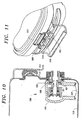
- Figure 11 shows a preferred anti-tampering embodiment designed to prevent tampering of sterilized instruments.
- a self-adhesive, thermal-paper label (not shown) is inserted into a slot 109 in such a way that it covers the front portion of a preferably metal bracket 111.
- the color of the thermal paper is changed by the heat generated by the heating plates of the armature, indicating that the cassette has been placed in the chamber for sterilization.
- an opening handle 113 is lifted and a crossbar 115 tears the label, indicating that the cassette 10 has been opened.
- a label retainer 117 can store a label with relevant information displayed thereon.
- the cassette lid 3 could also include a conventional bar-code identification system to organize and identify the cassette contents electronically.
- the invention also includes the bi-directional seal itself as well as a method of using the cassette in a sterilization process and apparatus employing vacuum for purging and steam sterilization.
- a steam sterilization cycle employs steam and vacuum for purging purposes.
- the inventive cassette is ideally adapted for such processes and apparatus since the cassette can function in a sealed manner during both vacuum and pressurized conditions. More particularly, the inventive method entails subjecting the cassette and the armature space surrounding it to a vacuum draw for pressure equalization between the two and air removal. Then, steam is used to purge air, the steam being removed using a vacuum again. The cassette is then pressurized and the instruments are subjected to steam sterilization conditions.
- the cassette pressure is then relieved, and the instruments are dried and any steam in the cassette is removed using vacuum.
- the cassette is then removed from the apparatus and either stored for later use of the instruments, or the instruments are used immediately. The specific details of such processing are disclosed in Applicant's aforementioned Canadian patent application.
- poppet valves have been disclosed to control ingress and egress of media to the interior of the cassette, other valve constructions could be used to provide the necessary isolation of or access to the cassette interior during sterilization, storage or the like.
- seal configurations other than o-rings may be employed to permit use of the cassette in the vacuum mode, pressure mode, and the storage mode.
- openings in the coupling body 63 are depicted for communication between the cassette interior and a sterilization apparatus, more or less opening could be employed. Similarly, while the openings are in the coupling body, other locations could be utilized. Further, while an elbow is disclosed as the duct for enhanced condensation pickup, other configurations may be employed depending on the orientation of the openings in the couplings situated within the cassette interior.
- the floating attachment of the couplings to the cassette tray is one embodiment of the invention but other floating configurations may be employed to allow engagement between couplings and probes of varying placement.
Landscapes
- Health & Medical Sciences (AREA)
- Epidemiology (AREA)
- Life Sciences & Earth Sciences (AREA)
- Animal Behavior & Ethology (AREA)
- General Health & Medical Sciences (AREA)
- Public Health (AREA)
- Veterinary Medicine (AREA)
- Apparatus For Disinfection Or Sterilisation (AREA)
- Dental Tools And Instruments Or Auxiliary Dental Instruments (AREA)
Abstract
Claims (23)
- Cassette de stérilisation comprenant :a) un plateau (1) ayant au moins une ouverture d'entrée et une ouverture de sortie pour une connexion à des sondes d'un appareil de stérilisation à vapeur adapté pour stériliser des instruments supportés par le plateau ; etb) un couvercle (3) s'articulant sur le plateau, le couvercle comprenant un joint (13) agencé le long d'une périphérie du couvercle, le couvercle étant adapté pour se déplacer entre une position ouverte, une position fermée, et une position intermédiaire, le couvercle, le joint, et le plateau formant une chambre fermée hermétiquement de stérilisation lorsque le couvercle est dans les positions fermée et intermédiaire ;c) chacune des ouvertures d'entrée et de sortie présentant un raccord (45, 47) situé dans celles-ci pour permettre la communication entre l'appareil de stérilisation à vapeur et la chambre de stérilisation.
- Cassette selon la revendication 1, dans laquelle le joint comprend en outre :i) un corps de joint continu (15) le long d'une périphérie du couvercle ;ii) des première (17) et deuxième (19) lèvres s'étendant à partir du corps de joint et reliées de façon pivotante à celui-ci ; etiii) une troisième lèvre (29) s'étendant à partir du corps de joint et espacée de la deuxième lèvre pour former un canal entre celles-ci ;iv) dans laquelle les première et deuxième lèvres assurent l'étanchéité dans la position intermédiaire et les première, deuxième et troisième lèvres assurent l'étanchéité dans la position fermée.
- Cassette selon la revendication 2, dans laquelle le couvercle présente un canal (25) le long d'une surface intérieure de celui-ci, le canal présentant des parois opposées (27, 29), le corps de joint étant agencé entre les parois opposées avec la première lèvre adjacente à une (29) des parois opposées et la troisième lèvre adjacente à l'autre (27) des parois opposées.
- Cassette selon la revendication 3, dans laquelle une des parois opposées s'étend à partir de la surface intérieure selon une distance supérieure à une largeur formée par la première lèvre et le corps de joint pour protéger la première lèvre au cours de la fermeture et de l'ouverture du couvercle.
- Cassette selon la revendication 2, dans laquelle les première et deuxième lèvres d'étanchéité sont liées au corps de joint par un élément s'étendant entre le corps de joint et chacune des première et deuxième lèvres, l'élément fournissant un point de pivotement pour le mouvement des première et deuxième lèvres.
- Cassette selon la revendication 1, dans laquelle le raccord de sortie présente au moins une ouverture positionnée dans la chambre, la au moins une ouverture espacée d'un fond du plateau, la cassette comprenant en outre un conduit attaché à la sortie d'une extrémité de celle-ci, avec une extrémité opposée du conduit positionnée à côté du fond du plateau pour assurer un canal pour la collecte de condensat au cours de la stérilisation à vapeur des instruments.
- Cassette selon la revendication 6, dans laquelle le conduit est un coude et l'extrémité opposée présente un filtre pour empêcher les débris d'entrer dans la au moins une ouverture.
- Cassette selon la revendication 1, dans laquelle chaque raccord d'entrée et de sortie comprend en outre un ensemble de corps de raccord et de joint monté de façon mobile à travers une paroi du plateau pour permettre l'auto-alignement avec des sondes de l'appareil de stérilisation tout en maintenant un joint d'étanchéité entre le corps de raccord et la paroi.
- Cassette selon la revendication 1 ou 2, dans laquelle chaque raccord d'entrée et de sortie présente une première valve pour permettre la communication entre l'appareil de stérilisation à vapeur et la chambre de stérilisation, et une seconde valve est fournie en tant que partie de la cassette pour libérer l'excès de pression dans la chambre de stérilisation, les première et seconde valves fermant également hermétiquement la chambre de stérilisation pour le stockage d'instruments stérilisés lorsque ladite chambre de stérilisation est complètement dégagée de l'appareil de stérilisation à vapeur.
- Cassette selon la revendication 9, dans laquelle chacun des raccords d'entrée et de sortie comprend en outre un corps de raccord monté de façon hermétique dans une paroi du plateau avec une première extrémité du corps de raccord agencée à l'extérieur de la chambre de stérilisation, et une seconde extrémité agencée à l'intérieur de la chambre de stérilisation, la première extrémité ayant une première ouverture et l'autre extrémité ayant au moins une seconde ouverture, la première valve étant agencée dans le corps de raccord, et la première extrémité ayant un dispositif d'étanchéité sur une surface périphérique de celle-ci, le dispositif d'étanchéité étant espacé de la paroi de sorte qu'un joint est formé entre la surface périphérique et une surface de sonde avant l'ouverture ou la fermeture de la première valve pour fermer hermétiquement la chambre de stérilisation par rapport à l'environnement ambiant.
- Cassette selon la revendication 10, dans laquelle la première extrémité du corps de raccord est de forme tubulaire et le dispositif d'étanchéité est un joint torique entourant une surface extérieure de la forme tubulaire.
- Cassette selon la revendication 9, dans laquelle chacun des raccords d'entrée et de sortie comprend en outre un corps de raccord monté de façon hermétique dans une paroi du plateau avec une première extrémité du corps de raccord agencée à l'extérieur de la chambre de stérilisation, et une seconde extrémité agencée à l'intérieur de la chambre de stérilisation, la première extrémité ayant une première ouverture et l'autre extrémité ayant au moins une seconde ouverture, la première valve étant agencée dans le corps de raccord entre les première et seconde ouvertures, la première valve étant contrainte dans une position fermée, et adaptée pour être ouverte lorsqu'une force est appliquée sur une face de valve contre la contrainte, la seconde valve étant agencée dans le corps de raccord et contrainte dans une position fermée et mobile jusqu'à une position ouverte lors de l'application d'une force appliquée à partir de l'intérieur de la chambre de stérilisation.
- Cassette selon la revendication 12, dans laquelle un ressort est positionné entre les première et seconde valves pour fournir la contrainte pour fermer chaque valve.
- Cassette selon la revendication 13, dans laquelle la première valve présente un alésage assurant la communication entre la première ouverture et la seconde valve de sorte que, lorsque la chambre de stérilisation est sous vide pour stockage, la contrainte de ressort et la pression atmosphérique maintiennent chacune de la première valve et de la seconde valve dans une position fermée.
- Cassette selon la revendication 12, dans laquelle un ressort est positionné entre les première et seconde valves pour fournir la contrainte pour fermer chaque valve, et la première valve présente un alésage assurant la communication entre la première ouverture et la seconde valve de sorte que, lorsque la chambre de stérilisation est sous vide pour stockage, la contrainte de ressort et la pression atmosphérique maintiennent chacune de la première valve et de la seconde valve dans la position fermée.
- Cassette selon la revendication 15, comprenant en outre un conduit attaché à la seconde extrémité du corps de raccord au niveau d'une extrémité de celui-ci, avec une extrémité opposée du conduit positionnée à côté du fond du plateau pour fournir un canal pour la collecte de condensat au cours de la stérilisation à vapeur des instruments.
- Cassette selon les revendications 1 et 2, dans laquelle au moins un raccord présente une valve pour permettre la communication entre l'appareil de stérilisation à vapeur et la chambre de stérilisation, la valve étant contrainte dans une position fermée et adaptée pour être ouverte lorsqu'une force est appliquée sur une face de la valve par une sonde de l'appareil de stérilisation à vapeur.
- Cassette selon les revendications 1 et 2, dans laquelle au moins un des raccords d'entrée et de sortie présente une première valve pour permettre la communication entre l'appareil de stérilisation à vapeur et la chambre de stérilisation, et une seconde valve est prévue en tant que partie de la cassette pour libérer l'excès de pression dans la chambre de stérilisation, les première et seconde valves fermant également hermétiquement la chambre de stérilisation pour le stockage d'instruments stérilisés lorsque ladite chambre de stérilisation est complètement dégagée de l'appareil de stérilisation à vapeur.
- Cassette selon la revendication 18, dans laquelle les raccords d'entrée et de sortie comprennent en outre un corps de raccord monté de façon hermétique dans une paroi du plateau avec une première extrémité du corps de raccord agencée à l'extérieur de la chambre de stérilisation, et une seconde extrémité agencée à l'intérieur de la chambre de stérilisation, la première extrémité ayant une première ouverture et l'autre extrémité ayant au moins une seconde ouverture, la première valve étant agencée dans un des corps de raccord, et la première extrémité ayant un dispositif d'étanchéité sur une surface périphérique de celle-ci, le dispositif d'étanchéité étant espacé de la paroi de sorte qu'un joint d'étanchéité est formé entre la surface périphérique et une surface de sonde avant l'ouverture ou la fermeture de la première valve pour fermer hermétiquement la chambre de stérilisation par rapport à l'environnement ambiant.
- Cassette selon la revendication 1, comprenant en outre un dispositif d'inviolabilité monté sur la cassette, le dispositif comprenant un matériau sensible à la chaleur, le matériau sensible à la chaleur indiquant si la cassette a été chauffée pour la stérilisation, le matériau sensible à la chaleur étant monté sur l'un du couvercle et du plateau, et le dispositif ayant un élément monté sur l'autre du couvercle et du plateau, de sorte que la séparation du couvercle et du plateau force l'élément à entrer en contact avec le matériau sensible à la chaleur afin d'indiquer que le couvercle et le plateau ont été ouverts.
- Joint flexible pour une cassette de stérilisation comprenant :i) un corps de joint continu adapté pour être monté sur un d'un couvercle et un plateau de la cassette de stérilisation ;ii) des première et deuxième lèvres s'étendant à partir du corps de joint et liées au corps de joint pour un mouvement pivotant ; etiii) une troisième lèvre s'étendant à partir du corps de joint et espacée de la deuxième lèvre pour former un canal entre celles-ci ;iv) dans lequel les première et deuxième lèvres coopèrent avec la cassette pour assurer l'étanchéité lorsque le plateau et le couvercle sont dans une première position et les première, deuxième et troisième lèvres coopèrent avec la cassette pour assurer l'étanchéité lorsque le joint flexible est dans la position fermée.
- Joint selon la revendication 21, dans lequel les première et deuxième lèvres sont liées au corps de joint par un élément s'étendant entre le corps de joint et chacune des première et deuxième lèvres, l'élément fournissant un point de pivotement pour le mouvement des première et deuxième lèvres.
- Procédé de stérilisation à vapeur d'instruments comprenant les étapes consistant à :a) fournir une cassette de stérilisation comprenant :i) un plateau ayant une ouverture d'entrée et une ouverture de sortie ; etii) un couvercle s'articulant sur le plateau, le couvercle comprenant un joint agencé le long d'une périphérie du couvercle, le couvercle étant adapté pour se déplacer entre une position ouverte, une position fermée, et une position intermédiaire, le couvercle, le joint, et le plateau formant une chambre de stérilisation lorsque le couvercle est dans les positions fermée et intermédiaire ;iii) chacune des ouvertures d'entrée et de sortie ayant un raccord situé dans celles-ci pour permettre la communication entre l'appareil de stérilisation à vapeur et la chambre de stérilisation,b) placer les instruments dans la chambre de stérilisation ;c) connecter l'entrée et la sortie aux sondes d'un appareil de stérilisation à vapeur ;d) soumettre les instruments à un cycle de stérilisation à vapeur avec des conditions de pression et de vide ; ete) retirer la cassette lors de l'achèvement du cycle de stérilisation à vapeur et, soit stocker les instruments dans la cassette sous des conditions de vide, soit retirer les instruments à partir de la cassette pour utilisation.
Applications Claiming Priority (3)
| Application Number | Priority Date | Filing Date | Title |
|---|---|---|---|
| CA2268042 | 1999-04-06 | ||
| CA002268042A CA2268042A1 (fr) | 1999-04-06 | 1999-04-06 | Appareil et methode pour la sterilisation a la vapeur des instruments medicaux et dentaires |
| PCT/CA2000/000376 WO2000059552A1 (fr) | 1999-04-06 | 2000-04-06 | Cassette pour appareil de sterilisation sous vide et a la vapeur |
Publications (2)
| Publication Number | Publication Date |
|---|---|
| EP1165150A1 EP1165150A1 (fr) | 2002-01-02 |
| EP1165150B1 true EP1165150B1 (fr) | 2004-06-30 |
Family
ID=4163436
Family Applications (2)
| Application Number | Title | Priority Date | Filing Date |
|---|---|---|---|
| EP00916719A Expired - Lifetime EP1165150B1 (fr) | 1999-04-06 | 2000-04-06 | Cassette pour appareil de sterilisation sous vide et a la vapeur |
| EP00916720A Expired - Lifetime EP1175231B1 (fr) | 1999-04-06 | 2000-04-06 | Sterilisateur a elimination d'air par aspiration |
Family Applications After (1)
| Application Number | Title | Priority Date | Filing Date |
|---|---|---|---|
| EP00916720A Expired - Lifetime EP1175231B1 (fr) | 1999-04-06 | 2000-04-06 | Sterilisateur a elimination d'air par aspiration |
Country Status (6)
| Country | Link |
|---|---|
| US (2) | US7641852B1 (fr) |
| EP (2) | EP1165150B1 (fr) |
| JP (2) | JP4656730B2 (fr) |
| CA (4) | CA2268042A1 (fr) |
| DE (2) | DE60011879T8 (fr) |
| WO (2) | WO2000059553A1 (fr) |
Cited By (1)
| Publication number | Priority date | Publication date | Assignee | Title |
|---|---|---|---|---|
| EP3363474A1 (fr) | 2017-02-21 | 2018-08-22 | Cefla Societa' Cooperativa | Support de plateau modulaire pour autoclave |
Families Citing this family (54)
| Publication number | Priority date | Publication date | Assignee | Title |
|---|---|---|---|---|
| CA2268042A1 (fr) | 1999-04-06 | 2000-10-06 | Scican, A Division Of Lux & Zwingenberger Ltd. | Appareil et methode pour la sterilisation a la vapeur des instruments medicaux et dentaires |
| JP4668453B2 (ja) * | 2001-04-27 | 2011-04-13 | オリンパス株式会社 | オートクレーブ装置 |
| US7641864B2 (en) | 2001-06-15 | 2010-01-05 | Avure Technologies Incorporated | Thermal sensor connector for pressure vessel |
| JP4257065B2 (ja) * | 2002-02-28 | 2009-04-22 | オリンパス株式会社 | 滅菌装置 |
| JP2003260118A (ja) * | 2002-03-11 | 2003-09-16 | Olympus Optical Co Ltd | 滅菌装置 |
| ITMI20030579A1 (it) * | 2003-03-24 | 2004-09-25 | M O Com S R L | Corpo di caldaia per apparecchi sterilizzatori a vapore, in particolare sterilizzatori per strumenti odontoiatrici, e procedimento per la sua realizzazione |
| JP2008528070A (ja) * | 2005-01-25 | 2008-07-31 | バット・ホールディング・アンパルトセルスカブ | 部材を滅菌する方法および装置 |
| ITMI20050349A1 (it) | 2005-03-07 | 2006-09-08 | W & H Sterilization Srl | Autoclave perfezionata a ciclo di lavoro abbreviabile contenitore da impiegare in detta autoclave e sistema di sterilizzazione completo impiegante detto contenitore |
| GB2439048A (en) * | 2006-06-15 | 2007-12-19 | Eschmann Holdings Ltd | Autoclave and sterilisation process |
| US20090081090A1 (en) * | 2007-09-26 | 2009-03-26 | Dayman Jeffrey G | Sterilizer with modular pressure housing for a sterilization chamber |
| US20090081089A1 (en) * | 2007-09-26 | 2009-03-26 | Dayman Jeffrey G | Fluid reservoir and receiver assembly |
| DE102008020586A1 (de) * | 2008-04-24 | 2009-10-29 | Kaltenbach & Voigt Gmbh | Gerät und Verfahren zum Desinfizieren, Sterilisieren und/oder Pflegen von ärztlichen, insbesondere zahnärztlichen Instrumenten |
| JP2008264571A (ja) * | 2008-06-16 | 2008-11-06 | Olympus Corp | 滅菌容器及び滅菌装置 |
| DE102010002030A1 (de) | 2009-03-20 | 2010-10-14 | Kaltenbach & Voigt Gmbh | Gerät zum Desinfizieren, Sterilisieren und/oderPflegen von ärztlichen, insbesondere zahnärztlichen Instrumenten |
| DE102010037659A1 (de) * | 2010-09-20 | 2012-03-22 | Aesculap Ag | Sterilbehälter |
| USD668349S1 (en) * | 2011-02-25 | 2012-10-02 | Scican Ltd. | Cassette sterilizer |
| FI20115350A0 (fi) * | 2011-04-12 | 2011-04-12 | Steris Europe Inc | Laite kiintoaineen erottamiseksi biojätesuspensiosta |
| DE102011086848A1 (de) * | 2011-11-22 | 2013-05-23 | Melag Medizintechnik Ohg | Bewegliches Teil mit Mitteln zum Anbringen eines Behälters für medizinische und zahnmedizinische Instrumente in einem Autoklaven |
| DE102012101832A1 (de) | 2012-03-05 | 2013-09-05 | Aesculap Ag | Chirurgischer Sterilisierbehälter und chirurgische Fluidextraktionsvorrichtung |
| DE102012101833A1 (de) | 2012-03-05 | 2013-09-05 | Aesculap Ag | Chirurgische Sterilisierbehälterwanne und chirurgischer Sterilisierbehälter mit einer Sterilisierbehälterwanne |
| US10760853B1 (en) * | 2012-03-15 | 2020-09-01 | Crosstex International, Inc. | Automated thermal exchange system for autoclave sterilizer |
| DE102012102370A1 (de) * | 2012-03-20 | 2013-09-26 | Aesculap Ag | Medizinische Dichtung und medizinischer Sterilisierbehälter |
| US8815174B2 (en) | 2012-08-17 | 2014-08-26 | American Sterilizer Company | Steam sterilizer |
| CN113230425B (zh) * | 2013-03-13 | 2023-07-14 | 史赛克公司 | 能够提供容器中的被灭菌手术器械是否被正确灭菌的提示的灭菌容器 |
| KR101451309B1 (ko) * | 2013-06-21 | 2014-10-15 | 주식회사 신흥 | 멸균 처리용 케이스 |
| US9669119B2 (en) * | 2014-05-06 | 2017-06-06 | American Sterilizer Company | Sterilizer |
| DE102015100454A1 (de) * | 2015-01-14 | 2016-07-14 | Aesculap Ag | Medizintechnischer Sterilisiercontainer mit aktiver Nachtrocknung |
| DE102015100455A1 (de) * | 2015-01-14 | 2016-07-14 | Aesculap Ag | Medizintechnischer Sterilisiercontainer mit passiver Nachtrocknung |
| WO2016138482A1 (fr) * | 2015-02-26 | 2016-09-01 | K&K Lukas LLC | Dispositif de désinfection à chaleur sèche et procédé d'utilisation |
| DE102015106641A1 (de) * | 2015-04-29 | 2016-11-03 | Aesculap Ag | Sterilisationssystem, Sterilisationsbehälter, Sterilisationsbehälter-Aufnahmevorrichtung und Sterilisator |
| KR101878459B1 (ko) * | 2015-09-24 | 2018-07-13 | 유동수 | 소용량 고속 고압증기 멸균 시스템 |
| US9671167B1 (en) * | 2015-11-13 | 2017-06-06 | American Sterilizer Company | Process for reducing the temperature of an effluent stream flowing out of a sterilization chamber |
| DE102016110572A1 (de) * | 2016-06-08 | 2017-12-14 | B. Braun Melsungen Ag | Medizintechnische Behandlungskammer in Leichtbauweise |
| DE102016112885A1 (de) | 2016-07-13 | 2018-01-18 | Aesculap Ag | Medizinischer Container mit schräger Deckeldichtung |
| IT201600131201A1 (it) * | 2016-12-27 | 2018-06-27 | W & H Sterilization Srl | Sistema di sterilizzazione a ciclo termodinamico perfezionato e relativo metodo |
| IT201700099949A1 (it) * | 2017-09-06 | 2019-03-06 | Fater Spa | Apparecchio di sterilizzazione, in particolare per la sterilizzazione di prodotti sanitari assorbenti post-consumo |
| CN107470233B (zh) * | 2017-09-12 | 2020-04-28 | 中国人民解放军第三军医大学第三附属医院 | 内窥镜清洗装置 |
| EP4389059B1 (fr) * | 2018-03-23 | 2025-10-29 | Log10 B.V. | Système de retraitement d'instruments médicaux réutilisables |
| US10568485B2 (en) * | 2018-07-12 | 2020-02-25 | Marilou Johnson | Shoe disinfecting assembly |
| EP3941381B1 (fr) | 2019-03-19 | 2025-01-15 | Medivators Inc. | Couvercles de plateaux pour endoscope aérés et systèmes |
| US12419718B2 (en) | 2019-06-20 | 2025-09-23 | Medivators Inc. | Absorbent liner, systems and methods of use |
| US11974721B2 (en) | 2019-06-20 | 2024-05-07 | Medivators Inc. | Endoscope storage cart, system and methods |
| WO2020256990A1 (fr) | 2019-06-20 | 2020-12-24 | Medivators Inc. | Plateau de stockage d'endoscope ayant des ouvertures et procédé d'utilisation |
| USD868992S1 (en) | 2019-07-17 | 2019-12-03 | Shenzhen Jienuoyi Science And Technology Co., Ltd | UVC LED sterilizer |
| CN111110883B (zh) * | 2020-01-21 | 2024-06-28 | 山东新华医疗器械股份有限公司 | 卡式脉动真空灭菌器 |
| EP4512359A3 (fr) | 2020-02-25 | 2025-05-07 | Medivators Inc. | Plateau de stockage d'endoscope empilable |
| CN111776609A (zh) * | 2020-06-24 | 2020-10-16 | 天津市宝坻区人民医院 | 一种医院病案管理用病案清洁消毒装置 |
| CN111888492A (zh) * | 2020-07-31 | 2020-11-06 | 宁波市海曙莱富医疗科技有限公司 | 一种灭菌器 |
| CN112675321A (zh) * | 2020-12-19 | 2021-04-20 | 张家港华菱医疗设备股份公司 | 蒸汽灭菌柜 |
| US20220373088A1 (en) * | 2021-05-21 | 2022-11-24 | Scican Ltd. | Door seal |
| CN113209323A (zh) * | 2021-05-25 | 2021-08-06 | 秦皇岛燕大源达机电科技股份有限公司 | 真空管式蒸汽杀菌器及其杀菌方法 |
| CN115300645B (zh) * | 2022-08-10 | 2024-02-20 | 浙江迈亚塔菌检智能科技有限公司 | 一种蒸汽灭菌装置 |
| CA3267948A1 (fr) * | 2022-09-30 | 2024-04-04 | American Sterilizer Company | Joint de ruissellement pour couvercle articulé de processeur de dispositif médical |
| EP4431119B1 (fr) | 2023-03-14 | 2025-11-05 | MELAG Medizintechnik GmbH & Co. KG | Procédé de régulation du niveau d'eau d'alimentation dans un stérilisateur à vapeur et stérilisateur à vapeur |
Family Cites Families (28)
| Publication number | Priority date | Publication date | Assignee | Title |
|---|---|---|---|---|
| US1746522A (en) * | 1927-07-12 | 1930-02-11 | Robert A Carleton | Low-tension fluid-heating apparatus |
| US2258746A (en) * | 1941-02-08 | 1941-10-14 | Simon Dickman | Steam generator |
| US2868616A (en) * | 1954-04-14 | 1959-01-13 | Edward J Poitras | Steam sterilization method |
| US3086263A (en) * | 1959-07-10 | 1963-04-23 | Huber Johann | Sterilizing apparatus |
| US3834872A (en) | 1972-07-03 | 1974-09-10 | Sybron Corp | Tabletop steam sterilizer |
| US4105407A (en) * | 1975-04-24 | 1978-08-08 | Sanderson Roger S | Sterilizing and storing medical items |
| JPS5922041Y2 (ja) * | 1978-08-15 | 1984-07-02 | 株式会社東芝 | 密閉容器 |
| JPS57170258A (en) * | 1981-04-13 | 1982-10-20 | Olympus Optical Co | Therapeutic device enclosing container |
| US4759909A (en) * | 1983-02-23 | 1988-07-26 | Joslyn Valve Corp. | Methods and apparatus for steam sterilization |
| US4783321A (en) | 1984-12-18 | 1988-11-08 | Instrumed, Inc. | Sterlization container system |
| US5160700A (en) * | 1989-10-04 | 1992-11-03 | H. W. Andersen Products, Inc. | Sterilizing system and method |
| US5271893A (en) * | 1989-11-24 | 1993-12-21 | Duncan Newman | Apparatus for steam sterilization of articles |
| CA2029682C (fr) * | 1989-11-24 | 1995-10-10 | Duncan Newman | Appareil de sterilisation a la vapeur et methode connexe |
| US5368821A (en) | 1990-03-28 | 1994-11-29 | Mdt Corporation | Sealable sterilizer cassette |
| US5207237A (en) | 1990-07-20 | 1993-05-04 | Kew Import/Export Inc. | Ozoneated liquid system |
| US5145642A (en) | 1991-01-31 | 1992-09-08 | Mdt Corporation | Load compensated water fill for a table top sterilizer |
| US5310524A (en) | 1992-02-11 | 1994-05-10 | Minntech Corporation | Catheter reprocessing and sterilizing system |
| EP0583465A1 (fr) * | 1992-03-13 | 1994-02-23 | American Sterilizer Company | Appareil et procede de sterilisation a l'aide d'un agent sterilisateur a multicomposant------------------------------------------ |
| US5266275A (en) | 1992-09-04 | 1993-11-30 | Faddis Chris G | Ozone sterilization system secondary safety chamber |
| US5344622A (en) | 1993-04-03 | 1994-09-06 | Cyclo3 pss Medical Systems, Inc. | Ozone sterilization system vapor humidification component with disposable water source |
| US5364590A (en) | 1993-05-07 | 1994-11-15 | American Sterlizer Company | Method for sterilization of objects |
| CA2127907C (fr) * | 1993-07-15 | 2006-07-11 | Ralf Sutter | Methode et dispositif de nettoyage intensif d'articles medicaux |
| DE9310601U1 (de) * | 1993-07-15 | 1993-09-02 | Siemens AG, 80333 München | Kassette zur Aufnahme ärztlicher, insbesondere zahnärztlicher Instrumente |
| US5759502A (en) | 1997-01-31 | 1998-06-02 | Sterilization Cassette Systems, Inc. | Instrument cassette having a mechanism to prevent lateral movement of an instrument support relative to an instrument support holder |
| US6066294A (en) * | 1997-08-21 | 2000-05-23 | Ethicon, Inc. | Multi-compartment sterilization system |
| DE19714298A1 (de) | 1997-04-07 | 1998-10-08 | Scican Division Of Lux & Zwing | Adapter für ein Sterilisationsgefäß in Form einer Kassette |
| US6010670A (en) | 1998-06-03 | 2000-01-04 | Berry, Jr.; Bernie B. | Sterilization assembly for instrument case |
| CA2268042A1 (fr) | 1999-04-06 | 2000-10-06 | Scican, A Division Of Lux & Zwingenberger Ltd. | Appareil et methode pour la sterilisation a la vapeur des instruments medicaux et dentaires |
-
1999
- 1999-04-06 CA CA002268042A patent/CA2268042A1/fr not_active Abandoned
-
2000
- 2000-04-06 US US09/958,035 patent/US7641852B1/en not_active Expired - Fee Related
- 2000-04-06 WO PCT/CA2000/000377 patent/WO2000059553A1/fr not_active Ceased
- 2000-04-06 JP JP2000609113A patent/JP4656730B2/ja not_active Expired - Lifetime
- 2000-04-06 CA CA2614685A patent/CA2614685C/fr not_active Expired - Lifetime
- 2000-04-06 EP EP00916719A patent/EP1165150B1/fr not_active Expired - Lifetime
- 2000-04-06 DE DE60011879T patent/DE60011879T8/de active Active
- 2000-04-06 CA CA002365828A patent/CA2365828C/fr not_active Expired - Lifetime
- 2000-04-06 CA CA002365829A patent/CA2365829C/fr not_active Expired - Lifetime
- 2000-04-06 EP EP00916720A patent/EP1175231B1/fr not_active Expired - Lifetime
- 2000-04-06 WO PCT/CA2000/000376 patent/WO2000059552A1/fr not_active Ceased
- 2000-04-06 JP JP2000609114A patent/JP4573079B2/ja not_active Expired - Lifetime
- 2000-04-06 DE DE60004509T patent/DE60004509T2/de not_active Expired - Lifetime
-
2011
- 2011-04-29 US US13/097,230 patent/US8795603B2/en not_active Expired - Fee Related
Cited By (1)
| Publication number | Priority date | Publication date | Assignee | Title |
|---|---|---|---|---|
| EP3363474A1 (fr) | 2017-02-21 | 2018-08-22 | Cefla Societa' Cooperativa | Support de plateau modulaire pour autoclave |
Also Published As
| Publication number | Publication date |
|---|---|
| CA2268042A1 (fr) | 2000-10-06 |
| US20110262301A1 (en) | 2011-10-27 |
| EP1175231B1 (fr) | 2003-08-13 |
| WO2000059553A1 (fr) | 2000-10-12 |
| US8795603B2 (en) | 2014-08-05 |
| EP1165150A1 (fr) | 2002-01-02 |
| DE60011879T2 (de) | 2005-08-25 |
| JP2002540852A (ja) | 2002-12-03 |
| JP4656730B2 (ja) | 2011-03-23 |
| CA2365829A1 (fr) | 2000-10-12 |
| US7641852B1 (en) | 2010-01-05 |
| CA2614685A1 (fr) | 2000-10-12 |
| JP2002540851A (ja) | 2002-12-03 |
| WO2000059552A1 (fr) | 2000-10-12 |
| CA2365828A1 (fr) | 2000-10-12 |
| CA2614685C (fr) | 2010-03-16 |
| CA2365828C (fr) | 2008-01-29 |
| DE60004509T2 (de) | 2004-05-19 |
| DE60004509D1 (de) | 2003-09-18 |
| JP4573079B2 (ja) | 2010-11-04 |
| DE60011879T8 (de) | 2005-12-15 |
| CA2365829C (fr) | 2007-08-07 |
| EP1175231A1 (fr) | 2002-01-30 |
| DE60011879D1 (de) | 2004-08-05 |
Similar Documents
| Publication | Publication Date | Title |
|---|---|---|
| EP1165150B1 (fr) | Cassette pour appareil de sterilisation sous vide et a la vapeur | |
| US4372921A (en) | Sterilized storage container | |
| US4416417A (en) | Sterilized storage container | |
| US8236253B2 (en) | Portable sterilizing apparatus for surgical and dental instruments | |
| US4754595A (en) | Method of sterilizing and storing articles | |
| US4247517A (en) | Sterilized storage container | |
| AU2010214151B2 (en) | Sterilisation services apparatus and method of sterilisation | |
| US4583643A (en) | Sterile bag | |
| US4584182A (en) | Sterilized storage container | |
| GB2105591A (en) | Combined gaseous hydrogen peroxide sterilizing chamber and storage unit for sterilized goods | |
| EP0044340B1 (fr) | Dispositif sensible a la pression et a la temperature et appareil pour articles a steriliser | |
| EP2501321B1 (fr) | Dispositif pour transporter des instruments médicaux | |
| US4374570A (en) | Sterilized storage container | |
| EP0007941A1 (fr) | Boite d'emmagasinage sterile et procede d'utilisation. | |
| CN111110883A (zh) | 卡式脉动真空灭菌器 | |
| CN211610861U (zh) | 卡式脉动真空灭菌器 | |
| US4558632A (en) | Sterilized storage container | |
| AU2021208996B2 (en) | Method and apparatus for realizing an aseptic connection between a valve unit and a tank container | |
| CA1198259A (fr) | Contenant sterilise pour la conservation de produits | |
| JPH1057452A (ja) | 滅菌装置および滅菌方法 | |
| JPH07116232A (ja) | 蒸気滅菌器に於けるフローティングシールの慣らし運転方法 | |
| NZ574910A (en) | Steam sterilisation in bag with surrounding pressure compensating environment to reduce mechanical stress on bag |
Legal Events
| Date | Code | Title | Description |
|---|---|---|---|
| PUAI | Public reference made under article 153(3) epc to a published international application that has entered the european phase |
Free format text: ORIGINAL CODE: 0009012 |
|
| 17P | Request for examination filed |
Effective date: 20011005 |
|
| AK | Designated contracting states |
Kind code of ref document: A1 Designated state(s): AT BE CH CY DE DK ES FI FR GB GR IE IT LI LU MC NL PT SE |
|
| 17Q | First examination report despatched |
Effective date: 20021126 |
|
| GRAP | Despatch of communication of intention to grant a patent |
Free format text: ORIGINAL CODE: EPIDOSNIGR1 |
|
| GRAS | Grant fee paid |
Free format text: ORIGINAL CODE: EPIDOSNIGR3 |
|
| GRAA | (expected) grant |
Free format text: ORIGINAL CODE: 0009210 |
|
| AK | Designated contracting states |
Kind code of ref document: B1 Designated state(s): DE FR GB IT NL |
|
| REG | Reference to a national code |
Ref country code: GB Ref legal event code: FG4D |
|
| REG | Reference to a national code |
Ref country code: IE Ref legal event code: FG4D |
|
| REF | Corresponds to: |
Ref document number: 60011879 Country of ref document: DE Date of ref document: 20040805 Kind code of ref document: P |
|
| ET | Fr: translation filed | ||
| PLBE | No opposition filed within time limit |
Free format text: ORIGINAL CODE: 0009261 |
|
| STAA | Information on the status of an ep patent application or granted ep patent |
Free format text: STATUS: NO OPPOSITION FILED WITHIN TIME LIMIT |
|
| 26N | No opposition filed |
Effective date: 20050331 |
|
| REG | Reference to a national code |
Ref country code: FR Ref legal event code: PLFP Year of fee payment: 16 |
|
| REG | Reference to a national code |
Ref country code: FR Ref legal event code: PLFP Year of fee payment: 17 |
|
| REG | Reference to a national code |
Ref country code: FR Ref legal event code: PLFP Year of fee payment: 18 |
|
| REG | Reference to a national code |
Ref country code: FR Ref legal event code: PLFP Year of fee payment: 19 |
|
| PGFP | Annual fee paid to national office [announced via postgrant information from national office to epo] |
Ref country code: GB Payment date: 20190326 Year of fee payment: 20 Ref country code: FR Payment date: 20190320 Year of fee payment: 20 |
|
| PGFP | Annual fee paid to national office [announced via postgrant information from national office to epo] |
Ref country code: NL Payment date: 20190328 Year of fee payment: 20 |
|
| PGFP | Annual fee paid to national office [announced via postgrant information from national office to epo] |
Ref country code: IT Payment date: 20190412 Year of fee payment: 20 Ref country code: DE Payment date: 20190318 Year of fee payment: 20 |
|
| REG | Reference to a national code |
Ref country code: DE Ref legal event code: R071 Ref document number: 60011879 Country of ref document: DE |
|
| REG | Reference to a national code |
Ref country code: NL Ref legal event code: MK Effective date: 20200405 |
|
| REG | Reference to a national code |
Ref country code: GB Ref legal event code: PE20 Expiry date: 20200405 |
|
| PG25 | Lapsed in a contracting state [announced via postgrant information from national office to epo] |
Ref country code: GB Free format text: LAPSE BECAUSE OF EXPIRATION OF PROTECTION Effective date: 20200405 |