EP1165162B1 - Nadellose zugangsvorrichtung - Google Patents
Nadellose zugangsvorrichtung Download PDFInfo
- Publication number
- EP1165162B1 EP1165162B1 EP00920130A EP00920130A EP1165162B1 EP 1165162 B1 EP1165162 B1 EP 1165162B1 EP 00920130 A EP00920130 A EP 00920130A EP 00920130 A EP00920130 A EP 00920130A EP 1165162 B1 EP1165162 B1 EP 1165162B1
- Authority
- EP
- European Patent Office
- Prior art keywords
- inner chamber
- access device
- plunger
- needleless access
- seal
- Prior art date
- Legal status (The legal status is an assumption and is not a legal conclusion. Google has not performed a legal analysis and makes no representation as to the accuracy of the status listed.)
- Expired - Lifetime
Links
- 239000012530 fluid Substances 0.000 claims abstract description 43
- 230000037361 pathway Effects 0.000 claims abstract description 16
- 238000007789 sealing Methods 0.000 claims description 7
- 238000010992 reflux Methods 0.000 description 4
- 239000003814 drug Substances 0.000 description 3
- 229940079593 drug Drugs 0.000 description 3
- 239000000314 lubricant Substances 0.000 description 3
- 208000012266 Needlestick injury Diseases 0.000 description 2
- 239000008280 blood Substances 0.000 description 2
- 210000004369 blood Anatomy 0.000 description 2
- 239000007788 liquid Substances 0.000 description 2
- 239000000463 material Substances 0.000 description 2
- 239000004033 plastic Substances 0.000 description 2
- 241000894006 Bacteria Species 0.000 description 1
- 239000004743 Polypropylene Substances 0.000 description 1
- 230000001154 acute effect Effects 0.000 description 1
- 230000001580 bacterial effect Effects 0.000 description 1
- 238000011109 contamination Methods 0.000 description 1
- 230000000994 depressogenic effect Effects 0.000 description 1
- 201000010099 disease Diseases 0.000 description 1
- 208000037265 diseases, disorders, signs and symptoms Diseases 0.000 description 1
- 230000036512 infertility Effects 0.000 description 1
- 229920000728 polyester Polymers 0.000 description 1
- -1 polypropylene Polymers 0.000 description 1
- 229920001155 polypropylene Polymers 0.000 description 1
- 229920002725 thermoplastic elastomer Polymers 0.000 description 1
- 210000003462 vein Anatomy 0.000 description 1
Images


Classifications
-
- A—HUMAN NECESSITIES
- A61—MEDICAL OR VETERINARY SCIENCE; HYGIENE
- A61M—DEVICES FOR INTRODUCING MEDIA INTO, OR ONTO, THE BODY; DEVICES FOR TRANSDUCING BODY MEDIA OR FOR TAKING MEDIA FROM THE BODY; DEVICES FOR PRODUCING OR ENDING SLEEP OR STUPOR
- A61M39/00—Tubes, tube connectors, tube couplings, valves, access sites or the like, specially adapted for medical use
- A61M39/22—Valves or arrangement of valves
- A61M39/26—Valves closing automatically on disconnecting the line and opening on reconnection thereof
- A61M2039/266—Valves closing automatically on disconnecting the line and opening on reconnection thereof where the valve comprises venting channels, e.g. to insure better connection, to help decreasing the fluid space upon disconnection, or to help the fluid space to remain the same during disconnection
-
- Y—GENERAL TAGGING OF NEW TECHNOLOGICAL DEVELOPMENTS; GENERAL TAGGING OF CROSS-SECTIONAL TECHNOLOGIES SPANNING OVER SEVERAL SECTIONS OF THE IPC; TECHNICAL SUBJECTS COVERED BY FORMER USPC CROSS-REFERENCE ART COLLECTIONS [XRACs] AND DIGESTS
- Y10—TECHNICAL SUBJECTS COVERED BY FORMER USPC
- Y10S—TECHNICAL SUBJECTS COVERED BY FORMER USPC CROSS-REFERENCE ART COLLECTIONS [XRACs] AND DIGESTS
- Y10S604/00—Surgery
- Y10S604/905—Aseptic connectors or couplings, e.g. frangible, piercable
Definitions
- This invention relates to a needleless access device for use with liquid flow and administrative apparatus for medical purposes.
- hypodermic needles to inject or withdraw fluids in medical applications has been standard practice for a number of years. Even where a patient already has an IV tubing set connected to a vein, hypodermic needles are frequency used to inject fluids into the IV tubing. Often a "Y connector" with a septum is provided in the tubing set for this very purpose. The needle is used to puncture the septum to administer the drug or other fluid, and the septum then sufficiently seals the opening to prevent airborne bacteria from entering the system. Septums are also common on drug vials, where the needle is inserted to withdraw a quantity of the drug.
- hypodermic needles leads to numerous needle-stick accidents. These are not only painful, but if the needle is contaminated, could cause serious disease or complications in the needle-stick victim.
- needleless access devices typically include a cap having an inlet opening and a body with an outlet opening.
- the devices are provided with a piston that in its normally closed position, seals the inlet opening of the device to prevent bacterial contamination and maintain sterility.
- U.S. Patent No. 5,439,451 discloses a Capless Medical Backcheck Valve for allowing liquid flow into an IV line.
- the backcheck valve includes a flexible elastomeric piston that has a flexible tubular wall.
- the use of such a flexible piston in a needleless access device tends to increase the interior hold-up volume within the device. Further, the flexible tubular wall may tend to impede fluid flow.
- the material required to make a flexible piston may require lubricants to function properly.
- blood and possibly other fluids may enter a needleless device through the outlet after the device has been used to administer fluid into IV tubing. This phenomenon is commonly referred to as reflux.
- a device according to the preamble of claim 1 is disclosed in US 5 730 418.
- a needleless access device has been invented which avoids reflux while minimizing hold-up volume, allows unimpeded fluid flow and requires no additional lubricants to function properly.
- the device is defined in claims 1.
- FIGS. 1-7 A preferred embodiment of the improved needleless access device 10 of the present invention is shown in FIGS. 1-7.
- the improved needleless access device 10 comprises a housing 12 made of a cap 13 and a body 14.
- the housing 12 has an inlet opening 22 and an outlet 24.
- the channel 15 is tapered so that the channel 15 and the inlet 22 form a standard female luer.
- the outlet 24 is a standard male luer.
- a plunger 16 with an integrally molded seal 18 is biased upwardly by a spring 28.
- An inner chamber 34 is formed in the body 14 of the housing 12.
- a vent 20 leads from the inner chamber 34 through the body 14 portion of the housing 12 to the atmosphere. The vent 20 allows air to move into and come out of the inner chamber 34.
- the cap 13 is ultrasonically welded to the body 14.
- the cap 13 and the body 14 are preferably made of a rigid plastic such as Ektar, which is a Cole polyester material.
- the plunger 16 is generally cylindrical in shape.
- the diameter of the plunger 16 varies along its length.
- the proximal end of the plunger 16 is sized to fit the inside of the channel 15 that is disposed within the cap 13.
- the plunger 16 is preferably made of a rigid plastic such as polypropylene.
- a first wiper seal 26 is molded on the perimeter of the plunger 16 near its top end 23.
- the bottom seal 18 is integrally formed on the plunger 16.
- the bottom seal 18 is generally cylindrical in shape.
- the bottom seal 18 has a diameter of approximately 5.59 mm (220 inches) and a thickness of approximately 1.91 mm (.075 inches).
- a main seal 32 is preferably formed just below the bottom seal 18.
- the main seal 32 is a wiper seal.
- the diameter of the main seal 32 is approximately the same as the diameter of the inner chamber 34.
- the first wiper seal 26, the bottom seal 18 and the main seal 32 are preferably made of a thermoplastic elastomer, such as Sanoprene.
- a fluid pathway or channel 60 is shown and includes an upper space 62, mid-channels 64 and a lower channel 66.
- the upper space 62 is located just below the flow channels 27 and is generally cylindrical in shape.
- six mid-channels 64 are disposed below the upper space 62.
- the mid-channels 64 are in fluid communication with the upper space 62 and are generally rectangular shaped in cross section.
- disposed below the mid-channels 64 is the lower channel 66.
- the lower channel 66 is in fluid communication with the mid-channels 64 and, like the upper space 62, is generally cylindrical in shape.
- the upper space 62 has a diameter of approximately 9.53 mm (.375 inches) and a width of 0.81 mm (.032 inches).
- the mid-channels 64 are preferably cut approximately 0.76 mm (.030 inches) into the cap, and have a width or channel width 1.27 mm (0.50 inches).
- the lower channel 66 has a diameter of 11.05 mm (.435 inches)and a width of 1.02 mm (.040 inches).
- conduits 70 are formed in the body 14.
- the conduits 70 are disposed between the lower channel 66 and an opening 25 of the outlet 24.
- Each conduit 70 preferably has two slanting sidewalls 72 and an open end 74.
- the conduits 70 form a fluid flow path from the channel 60 to the opening 25 of the outlet 24.
- the outlet 24 is a cylindrical opening disposed in the lower portion of the body 14.
- the outlet 24 is generally cylindrical in shape.
- An opening 25 is located at the uppermost portion of the outlet 24.
- the opening is rectangular shaped in the cross section shown in FIG. 3.
- the opening 25 receives fluid from the conduit 70 and passes it the outlet 24.
- the outlet 24 permits the fluid to flow out of the body 14 to its intended location, such as an IV line.
- the inner chamber 34 is formed by a perimeter wall 35 in the body 14 portion of the housing 12.
- the inner chamber 34 has a top portion 36, a bottom portion 38 and a perimeter wall 35.
- the perimeter wall 35 is generally cylindrical in shape and has a tapered end portion 46. In a preferred embodiment the perimeter wall 35 is rigid.
- the inner chamber 34 is designed to receive air that enters through the vent 20 after fluid is injected using the device 10.
- the diameter of the perimeter wall 35 is approximately 6.99 mm (.275 inches) and the length,of the perimeter wall 35 is 16.38 mm (.645 inches).
- the tapered end portion 46 preferably has a diameter of approximately .255 inches and a length of 1.91 mm (.075 inches).
- vents 20 are located between a bottom portion 48 of the end portion 46 of the inner chamber 34 and the open threaded exit portion 50 of the body 14.
- the vents 20 are rectangular shaped in the cross section.
- the vents 20 are oriented parallel to the central axis 11. Altematively, the vents 20 may be oriented at an acute, obtuse or a right angle with respect to the central axis.
- the vents 20 permit air to enter into and pass out of the inner chamber 34.
- the vents 20 have a length of approximately 3.30 mm (.130 inches).
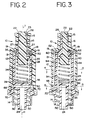
- the plunger 16 is in a first position.
- the first wiper seal 26 is at the top 23 of the cap 13 and acts to seal the top of the channel 15 and the inlet 22.
- the ends 19 of the bottom seal 18 abut the cap 13, thereby preventing fluid from the flow channels 27 from moving into the channel 60.
- the main seal 32 abuts the perimeter wall 35 at the top 36 of the inner chamber 34 and thereby seals the inner chamber 34 from fluid that may be in the channel 60.
- the inner chamber 34 is filled with air.
- the plunger 16 shifts downward toward a second position shown in FIG. 6. In this second position, the plunger 16 is depressed to a level such that the first wiper seal 26 is just below the tops of the flow channels 27 and the bottom seal 18 is within the inner chamber 34. As a result, fluid injected by the syringe 8 flows out the tip, over the top 23 of the plunger 16, through the flow channels 27 and into the channel 60.
- the fluid flows from the upper space 62, to the mid-channels 64, and then to the lower channel 66. From the lower channel the fluid flows through the conduits 70 to the opening 25 and then finally out through the outlet 24. Fluid also fills the portion of the inner chamber 34 between the bottom seal 18 and the upper space 62.
- the plunger 16 when the syringe 8 is pulled out, the plunger 16 is biased in an upward direction by the spring 28 from the second position shown in FIG. 6 back to the first position shown in FIGS. 2 and 3. As the plunger shifts upward the fluid in the inner chamber 34 is pushed out of the inner chamber 34 through the channel 60. Also, as the plunger is shifted upward out of the inner chamber 34, air enters and fills the empty space in the inner chamber 34 through the vent 20. The air entering the inner chamber 34 prevents the reflux of fluid and blood that may otherwise have come back through the outlet 24 because of the empty space in the inner chamber 34. After the syringe 8 is removed, the plunger 16 returns to the first position shown in FIGS. 2 and 3.
- FIGS. 8 and 9 The second preferred embodiment of an improved needleless access device 110 of the present invention is shown in FIGS. 8 and 9.
- the device 110 is generally the same as the device 10 of FIGS. 1-6, and the similar elements have reference numbers that differ by an addend of 100. However, the exact same plunger 16 used in the first embodiment can be used in this second embodiment.
- the second embodiment has a vent 20 that is aligned horizontally with respect to the inner chamber 134 or perpendicular with respect to the central axis 11, as opposed to the two vertical 20 vents of the first embodiment. Further, the second embodiment only has one mid-channel 164 that is rectangular shaped in the cross section, as shown in FIG. 9, and connects directly to the outlet 124 via a lower channel 166. In addition, as shown in FIG. 9, the second embodiment includes voids 180 that are formed in the body. The voids 180 are semicircular openings disposed in the body and are approximately the same length as the channel 160.
- FIG. 10 A third embodiment of the needleless access device 210 of the present invention is shown in FIG. 10.
- the device 210 is generally the same as device 10 of FIGS. 1-6, and the similar elements have reference numbers that differ by an addend of 200.
- the third embodiment has one horizontally oriented vent 220 instead of two.
- the third embodiment has a cylindrical shaped mid-channel 264 that is formed between the cap 213 and the body 214.
- the third embodiment has an opening 225 that is circular shaped in cross section.
- FIG. 11 A fourth embodiment of the needleless access device 310 of the present invention is shown in FIG. 11.
- the device 310 is generally the same as device 10 of FIGS. 1-6, and the similar elements have reference numbers that differ by an addend of 300.
- the fourth embodiment has one vertically oriented vent 320.
- the fourth embodiment has a cylindrical shaped mid-channel 364 that is formed between the cap 313 and the body 314.
- the fourth embodiment has an opening 325 that is circular shaped in cross section.
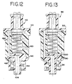
- a fifth embodiment of the needleless access device 410 is shown in FIG. 12.
- the device 410 is generally the same as device 10 of FIGS. 1-3, and the similar elements have reference numbers that differ by an addend of 400.
- the fifth embodiment has a horizontal vent 420 as opposed to a vertical vent.
- the body 414 in the fifth embodiment has tabs 490, because the cap 413 is molded around the body 414 as opposed to ultrasonically welded.
- the fifth embodiment has one semi-cylindrical mid channel 464 and a lower channel 466 that is directly connected to the outlet 424 as opposed to an opening.
- FIG. 13 A sixth embodiment of the needleless access device 510 is shown in FIG. 13.
- the device 510 is generally the same as the device 10 of FIGS. 1-6, and the similar elements have reference numbers that differ by an addend of 500.
- the sixth embodiment is similar to the fifth embodiment, however, it has one vertical vent 520 on the right side of the device 510 (as shown from the cross section in FIG. 13).
- the fifth embodiment also has tabs 590, because the cap 513 is molded around the body 514.
- plungers there are several embodiments of plungers that may be used with any one of the foregoing devices 10, 110, 210, 310, 410 and 510. These are shown in FIGS. 14-23.
- the second embodiment for a plunger for the present invention is shown in FIG. 14.
- the plunger 116 is generally the same as the plunger 16 for the device 10 of FIG. 7, and the similar elements have reference numbers that differ by an addend of 100.
- the main seal 132 is comprised of molded rings 152 instead of a wiper seal 132.
- FIG. 15 A third embodiment of the plunger 216 is shown in FIG. 15.
- the plunger 216 is generally the same as the plunger 16 of FIG. 7.
- the plunger 216 in FIGS. 15-18 has a main seal that is concave shaped at the ends 206 and has a top edge 202 and a bottom edge 204 that, when the plunger 200 is inserted in the inner chamber 34, contact the perimeter wall 35.
- FIG. 16 A fourth embodiment of the improved plunger 316 is shown in FIG. 16.
- the plunger 316 is generally the same as the plunger 16 of FIG. 7.
- the plunger 316 uses two wiper seals 332 instead of a single wiper seal as the main seal 332. Two wiper seals 332 may be more useful for high pressure applications.
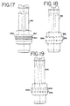
- FIG. 17 A fifth embodiment of the plunger 416 is shown in FIG. 17.
- the plunger 416 is generally the same as the plunger 16 of FIG. 7.
- the plunger 416 uses, however, a band seal as the main seal 432 instead of a wiper seal.
- the band seal 432 is generally cylindrical in shape and has tapered ends 406 that contact the perimeter wall of the inner chamber.
- a sixth embodiment of the plunger 516 is shown. Instead of a wiper seal that is shown in FIG. 7, this embodiment uses a main seal 532 that has ends 506 that are generally trapezoidal shaped in cross section.
- the main seal 618 of this embodiment has triangular shaped ends 606.
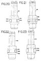
- FIG. 20 A seventh embodiment of the plunger 716 is shown in FIG. 20.
- the plunger 716 in FIG. 20 has a groove 752. Disposed within the groove is an o-ring 754, that is circular shaped in cross section. When the plunger 716 is placed in the device 10, the o-ring 754 abuts the perimeter wall 35 of the inner chamber 34.
- the plunger 816 has a groove 802 and a sealing ring 804 that is elliptical shaped in cross section. When the plunger 816 is placed in the device 10 the sealing ring 804 abuts the perimeter wall 35 of the inner chamber 34.
- a ninth embodiment of the plunger 916 is shown.
- This embodiment also has a groove 952 and main sealing ring 954.
- the cross-sectional shape of the sealing ring shown in FIG. 22 has a plurality of curved edges 956.
- the plunger 1016 shown in FIG. 23 is similar to the one in FIG. 22 and has a sealing ring 1006 that also has a cross-sectional shape which has a plurality of curved edges 1008.
Landscapes
- Health & Medical Sciences (AREA)
- Heart & Thoracic Surgery (AREA)
- Pulmonology (AREA)
- Engineering & Computer Science (AREA)
- Anesthesiology (AREA)
- Biomedical Technology (AREA)
- Hematology (AREA)
- Life Sciences & Earth Sciences (AREA)
- Animal Behavior & Ethology (AREA)
- General Health & Medical Sciences (AREA)
- Public Health (AREA)
- Veterinary Medicine (AREA)
- Infusion, Injection, And Reservoir Apparatuses (AREA)
- Undergarments, Swaddling Clothes, Handkerchiefs Or Underwear Materials (AREA)
- Adornments (AREA)
Claims (20)
- Nadellose Zugangsvorrichtung (10), umfassend:a) ein Gehäuse (12), eine Innenwand (35) und eine Außenwand umfassend, das Gehäuse (12) hat(I) einen Einlass (22) und einen Auslass (24),(II) einen Fluidweg (60), der eine Fluidverbindung zwischen dem Einlass (22) und dem Auslass (24) einrichtet, und(III) eine Innenkammer (34), die innerhalb der Innenwand ausgebildet ist,b) einen vorgespannten Kolben (16), angeordnet in der Innenkammer (34) und bewegbar zwischen einer ersten Position, in der Fluidverbindung zwischen dem Einlass (22) und dem Auslass (24) durch den Fluidweg verhindert ist, und einer zweiten Position, in der Fluidverbindung zwischen dem Einlass (22) und dem Auslass (24) in dem Fluidweg (60) eingerichtet ist, wobei der Kolben normalerweise in die erste Position vorgespannt ist,c) eine Hauptdichtung (32), angeordnet auf dem Kolben und die Innenkammer (34) gegen den Fluidweg (60) abdichtend,d) eine weitere Dichtung (18), angeordnet auf dem Kolben und den Fluidweg (60) gegen den Einlass (22) abdichtend, wenn der Kolben (16) in der ersten Position ist, unde) einen Luftdurchlass (20) zwischen der Innenkammer (34) und dem Äußeren des Gehäuses (12), um zu ermöglichen, dass Luft aus der innenkammer (34) austreten und in die Innenkammer (34) eintreten kann, wenn der Kolben (16) zwischen der ersten und der zweiten Position bewegt wird,dadurch gekennzeichnet, dass der Fluidweg (60) durch wenigstens einen zwischen der Innenwand (35) und der Außenwand ausgebildeten Strömungskanal definiert ist.
- Nadellose Zugangsvorrichtung (10) nach Anspruch 1, wobei ein spannbares Element in der Innenkammer (34) den Kolben (16) in Richtung der ersten Position vorspannt.
- Nadellose Zugangsvorrichtung (10) nach Anspruch 1, wobei die Hauptdichtung (32) eine Abstreiferdichtung ist, die als ein Teil des Kolbens (16) aufgepresst ist.
- Nadellose Zugangsvorrichtung (10) nach Anspruch 1, wobei die Hauptdichtung (32) gleitend mit der Innenkammer (34) in Eingriff kommt.
- Nadellose Zugangsvorrichtung (10) nach Anspruch 1, wobei der Kolben eine aufgepresste untere Dichtung (18) aufweist, die angeordnet ist, um den Fluidweg (60) abzudichten.
- Nadellose Zugangsvorrichtung (10) nach Anspruch 2, wobei das spannbare Element eine Feder (28) ist.
- Nadellose Zugangsvorrichtung (10) nach Anspruch 1, wobei die Innenkammer (34) teilweise durch eine Umfangswand (35) definiert ist.
- Nadellose Zugangsvorrichtung (10) nach Anspruch 7, wobei die Umfangswand starr ist.
- Nadellose Zugangsvorrichtung (10) nach Anspruch 7, wobei die Umfangswand (35) einen ringförmigen Querschnitt hat.
- Nadellose Zugangsvorrichtung (10) nach Anspruch 1, wobei die Innenkammer (34) eine im Allgemeinen zylindrische Form hat.
- Nadellose Zugangsvorrichtung (10) nach Anspruch 1, wobei der Fluidweg (60) einen oberen Raum (62), einen Mittelkanal (64) und einen unteren Kanal (66) umfasst.
- Nadellose Zugangsvorrichtung (10) nach Anspruch 11, wobei der Mittelkanal (64) eine Valzahl von rechteckig ausgebildeten Kanälen umfasst.
- Nadellose Zugangsvorrichtung (10) nach Anspruch 1, wobei die Hauptdichtung (32) eine Abstreifdichtung ist.
- Nadellose Zugangsvorrichtung (10) nach Anspruch 1, wobei Luft durch den Luftdurchlass (20) aus der Innenkammer (34) austritt, während sich der Kolben (16) von der ersten Position auf die zweite Position bewegt, und wobei Luft durch den Luftdurchlass (20) in die Innenkammer (34) eintritt, während sich der Kolben (16) von der zweiten Position auf die erste Position bewegt.
- Nadellose Zugangsvorrichtung (10) nach Anspruch 1, wobei der Fluidweg und die Innenkammer (34) durch eine Leitung verbunden sind.
- Nadellose Zugangsvorrichtung (10) nach Anspruch 1, wobei der Luftdurchlass (20) in Bezug auf die Mittelachse der Innenkammer (34) parallel ausgerichtet ist.
- Nadellose Zugangsvorrichtung (10) nach Anspruch 1, wobei der Luftdurchlass (20) in Bezug auf die Mittelachse der Innenkammer (34) senkrecht ausgerichtet ist.
- Nadellose Zugangsvorrichtung nach Anspruch 1, wobeia) ein Gehäuse (12) eine Kappe (13) und einen Körper (14) umfasst, wobei die Innenkammer (34) in dem Körper (14) ausgebildet ist und der Fluidweg (60) zwischen der Kappe (13) und dem Körper (14) ausgebildet ist, der Fluidweg (60) einen oberen Raum (62), Mittelkanäle (64) und einen unteren Kanal (66) umfasst undb) der vorgespannte Kolben (16) eine erste Dichtung (26) und eine Hauptdichtung (32) umfasst, wobei die erste Dichtung (26) den Fluidweg (60) gegen den Einlass abdichtet und die Hauptdichtung (32) die Innenkammer (34) gegen den Fluidweg (60) abdichtet.
- Nadellose Zugangsvorrichtung (10) nach Anspruch 18, wobei die Hauptdichtung (32) eine Abstreifdichtung ist.
- Nadellose Zugangsvorrichtung (10) nach Anspruch 18, wobei der Luftdurchlass (20) in einem rechten Winkel zu einer Mittelachse der Innenkammer (34) ausgerichtet ist, um Luft zu ermöglichen, in die Innenkammer (34) einzutreten und aus dieser auszutreten, wenn der Kolben (16) zwischen der ersten und der zweiten Position bewegt wird.
Applications Claiming Priority (3)
| Application Number | Priority Date | Filing Date | Title |
|---|---|---|---|
| US09/286,280 US6228069B1 (en) | 1999-04-05 | 1999-04-05 | Needleless access device |
| US286280 | 1999-04-05 | ||
| PCT/US2000/008958 WO2000059561A1 (en) | 1999-04-05 | 2000-04-04 | Needleless access device |
Publications (3)
| Publication Number | Publication Date |
|---|---|
| EP1165162A1 EP1165162A1 (de) | 2002-01-02 |
| EP1165162A4 EP1165162A4 (de) | 2004-07-07 |
| EP1165162B1 true EP1165162B1 (de) | 2006-06-21 |
Family
ID=23097883
Family Applications (1)
| Application Number | Title | Priority Date | Filing Date |
|---|---|---|---|
| EP00920130A Expired - Lifetime EP1165162B1 (de) | 1999-04-05 | 2000-04-04 | Nadellose zugangsvorrichtung |
Country Status (6)
| Country | Link |
|---|---|
| US (1) | US6228069B1 (de) |
| EP (1) | EP1165162B1 (de) |
| AT (1) | ATE330650T1 (de) |
| CA (1) | CA2368202C (de) |
| DE (1) | DE60028948T2 (de) |
| WO (1) | WO2000059561A1 (de) |
Families Citing this family (57)
| Publication number | Priority date | Publication date | Assignee | Title |
|---|---|---|---|---|
| US7789864B2 (en) * | 1996-11-18 | 2010-09-07 | Nypro Inc. | Luer-activated valve |
| US20020013556A1 (en) * | 1996-11-18 | 2002-01-31 | Cote Andrew L. | Swabbable luer-activated valve |
| US6482188B1 (en) * | 1999-10-01 | 2002-11-19 | Mission Medical Devices, Inc. | Nonvented needle-free injection valve |
| US6695817B1 (en) | 2000-07-11 | 2004-02-24 | Icu Medical, Inc. | Medical valve with positive flow characteristics |
| EP1427472A2 (de) * | 2001-08-22 | 2004-06-16 | Nypro Inc. | Medizinisches ventil mit expandierbarem glied |
| JP4339682B2 (ja) * | 2001-08-23 | 2009-10-07 | オキュペイショナル・アンド・メディカル・イノベイションズ・リミテッド | 逆流防止バルブ |
| DE60220427T2 (de) * | 2001-10-09 | 2008-01-31 | Halkey-Roberts Corp., St. Petersburg | Männliches luer-ventil |
| US7753892B2 (en) * | 2001-11-13 | 2010-07-13 | Nypro Inc. | Anti-drawback medical valve |
| US7837658B2 (en) * | 2001-11-13 | 2010-11-23 | Nypro Inc. | Anti-drawback medical valve |
| ITMI20020819A1 (it) * | 2002-04-18 | 2003-10-20 | Gambro Lundia Ab | Elemento di connessione e dispositivo di collegamento per tubazioni ad uso medicale |
| US7357792B2 (en) * | 2002-10-29 | 2008-04-15 | Nypro Inc. | Positive push medical valve with internal seal |
| US6871838B2 (en) * | 2003-04-03 | 2005-03-29 | B. Braun Medical Inc. | Injection port valve |
| CA2529429C (en) * | 2003-06-17 | 2009-10-20 | Filtertek Inc. | Fluid handling device and method of making same |
| US7914502B2 (en) | 2003-07-31 | 2011-03-29 | Nypro Inc. | Anti-drawback medical valve |
| ES2380911T3 (es) | 2004-11-05 | 2012-05-21 | Icu Medical, Inc. | Conector médico que tiene características de alto flujo |
| US7887519B2 (en) * | 2005-01-14 | 2011-02-15 | Nypro Inc. | Valve with internal lifter |
| US7510545B2 (en) | 2005-02-09 | 2009-03-31 | B. Braun Medical Inc. | Needleless access port valves |
| US7114701B2 (en) * | 2005-03-02 | 2006-10-03 | B. Braun Medical, Inc. | Needleless access port valves |
| US8100866B2 (en) | 2005-03-24 | 2012-01-24 | B. Braun Medical Inc. | Needleless access port valves |
| US7615035B2 (en) * | 2005-03-24 | 2009-11-10 | B. Braun Medical Inc. | Needleless access port valves |
| US7314061B2 (en) | 2005-03-25 | 2008-01-01 | B. Braun Medical Inc. | Needleless access port valves |
| EP1896121B1 (de) | 2005-05-16 | 2012-11-07 | Nypro Inc. | Medizinisches antirücklaufventil |
| CA2655656A1 (en) * | 2005-08-29 | 2007-03-08 | Medigard Limited | Improvements to a one way valve |
| US9695953B2 (en) | 2006-02-14 | 2017-07-04 | B. Braun Medical Inc. | Needleless access port valves |
| US7591449B2 (en) * | 2006-02-14 | 2009-09-22 | B. Braun Medical Inc. | Needleless access port valves |
| US8002755B2 (en) | 2006-04-11 | 2011-08-23 | Nypro Inc. | Anti-drawback medical valve and method |
| US7867204B2 (en) * | 2006-05-04 | 2011-01-11 | B. Braun Medical Inc. | Needleless access port valves |
| US20070270756A1 (en) * | 2006-05-22 | 2007-11-22 | Peter Peppel | Needleless access port valves |
| CA2660838A1 (en) * | 2006-08-11 | 2008-02-21 | Nypro Inc. | Medical valve with expandable member |
| US8221363B2 (en) | 2006-10-18 | 2012-07-17 | Baxter Healthcare S.A. | Luer activated device with valve element under tension |
| US7981090B2 (en) | 2006-10-18 | 2011-07-19 | Baxter International Inc. | Luer activated device |
| US7753338B2 (en) | 2006-10-23 | 2010-07-13 | Baxter International Inc. | Luer activated device with minimal fluid displacement |
| ES2362449T3 (es) | 2006-10-25 | 2011-07-05 | Icu Medical, Inc. | Conector médico. |
| US8454579B2 (en) | 2009-03-25 | 2013-06-04 | Icu Medical, Inc. | Medical connector with automatic valves and volume regulator |
| WO2010117791A1 (en) * | 2009-03-30 | 2010-10-14 | Np Medical Inc. | Medical valve with distal seal actuator |
| PT2445572T (pt) | 2009-06-22 | 2018-11-02 | Np Medical Inc | Válvula médica com vedação de contrapressão melhorada |
| WO2011011462A1 (en) | 2009-07-20 | 2011-01-27 | Optiscan Biomedical Corporation | Adjustable connector and dead space reduction |
| USD644731S1 (en) | 2010-03-23 | 2011-09-06 | Icu Medical, Inc. | Medical connector |
| EP2585165B1 (de) | 2010-05-03 | 2017-06-21 | Optiscan Biomedical Corporation | Einstellbarer verbinder, verbesserter flüssigkeitsfluss und verringerter gerinnungsrisiko |
| US8758306B2 (en) | 2010-05-17 | 2014-06-24 | Icu Medical, Inc. | Medical connectors and methods of use |
| US9138572B2 (en) | 2010-06-24 | 2015-09-22 | Np Medical Inc. | Medical valve with fluid volume alteration |
| US9017295B2 (en) * | 2010-09-02 | 2015-04-28 | Skill Partner Limited | Syringe adapter with a ball-typed valve |
| US9067049B2 (en) * | 2011-07-25 | 2015-06-30 | Carefusion 303, Inc. | Providing positive displacement upon disconnection using a connector with a dual diaphragm valve |
| CN104955518B (zh) * | 2012-10-01 | 2017-03-29 | 塞考利特公司 | 将要素传送到可植入装置的可植入连接器组件和方法 |
| US9212772B2 (en) * | 2013-03-15 | 2015-12-15 | Pacific Hospital Supply Co., Ltd | Needle free connector |
| AU2014364218B2 (en) | 2013-12-11 | 2019-06-06 | Icu Medical, Inc. | Check valve |
| WO2015145998A1 (ja) * | 2014-03-28 | 2015-10-01 | テルモ株式会社 | 医療用コネクタ |
| EP3199200B1 (de) * | 2014-09-24 | 2024-09-11 | Terumo Kabushiki Kaisha | Medizinischer verbinder |
| USD786427S1 (en) | 2014-12-03 | 2017-05-09 | Icu Medical, Inc. | Fluid manifold |
| USD793551S1 (en) | 2014-12-03 | 2017-08-01 | Icu Medical, Inc. | Fluid manifold |
| WO2016152016A1 (ja) * | 2015-03-26 | 2016-09-29 | テルモ株式会社 | オスコネクタ及び輸液セット |
| WO2016157829A1 (ja) * | 2015-03-27 | 2016-10-06 | テルモ株式会社 | 医療用コネクタ |
| US20180193630A1 (en) * | 2017-01-06 | 2018-07-12 | Dale Medical Products, Inc. | Non-luer compatible administration port |
| MY185708A (en) * | 2018-05-14 | 2021-05-31 | Kim Seng @ Chong Kim Sang Chong | Catheter valve |
| DE102019217309A1 (de) * | 2019-11-08 | 2021-05-12 | B. Braun Melsungen Aktiengesellschaft | Gegendorn-Kupplungselement, Dorn-Kupplungselement sowie Kupplungssystem für ein geschlossenes Fluidtransfersystem |
| WO2022102300A1 (ja) * | 2020-11-12 | 2022-05-19 | テルモ株式会社 | 医療用コネクタ |
| US20240328553A1 (en) * | 2023-03-28 | 2024-10-03 | Carefusion 303, Inc. | Connector coupling assembly |
Family Cites Families (20)
| Publication number | Priority date | Publication date | Assignee | Title |
|---|---|---|---|---|
| GB1192986A (en) | 1967-08-31 | 1970-05-28 | Eschmann Bros & Walsh Ltd | Intravenous Valve Assembly |
| US3831629A (en) | 1972-01-24 | 1974-08-27 | Halkey Roberts Corp | Check valve |
| US3965910A (en) | 1975-04-28 | 1976-06-29 | Walpak Company | Urinary irrigation valve |
| US4429856A (en) | 1981-12-18 | 1984-02-07 | Mallinckrodt, Inc. | Inflation valve |
| US5353837A (en) | 1986-03-04 | 1994-10-11 | Deka Products Limited Partnership | Quick-disconnect valve |
| US4668215A (en) | 1986-05-15 | 1987-05-26 | Dexide, Inc. | Irrigator-evacuator control for surgical procedures |
| US5049128A (en) | 1990-02-06 | 1991-09-17 | Duquette Irene A | Valved infusion port |
| US4991820A (en) | 1990-02-09 | 1991-02-12 | Allied Healthcare Products, Inc. | Fluid conduit coupler |
| US5222947A (en) | 1990-04-18 | 1993-06-29 | Amico Elio D | Self recapping injection needle assembly |
| US5006114A (en) | 1990-04-20 | 1991-04-09 | Rogers Bobby E | Medical valve assembly |
| US5147333A (en) | 1991-05-13 | 1992-09-15 | Burron Medical Inc. | Needleless injection port with automatic backcheck valve |
| US5184652A (en) | 1991-07-02 | 1993-02-09 | Fan Chin Fu | Universal medication port |
| US5201725A (en) | 1991-09-26 | 1993-04-13 | Ivac | Needle free i.v. adapter |
| US5242432A (en) | 1991-09-26 | 1993-09-07 | Ivac | Needleless adapter |
| US5284475A (en) | 1992-07-21 | 1994-02-08 | Mackal Glenn H | Luer valve adapter with expandable end |
| US5347992A (en) | 1993-01-22 | 1994-09-20 | Karl Storz Endoscopy America, Inc. | Single axis three way selector valve for endoscopes |
| US5439451A (en) | 1994-03-22 | 1995-08-08 | B. Braun Medical, Inc. | Capless medical backcheck valve |
| US5730418A (en) * | 1996-09-30 | 1998-03-24 | The Kipp Group | Minimum fluid displacement medical connector |
| CN1172727C (zh) * | 1996-12-16 | 2004-10-27 | Icu医学有限公司 | 正向流动阀 |
| CA2357740A1 (en) * | 1999-01-27 | 2000-08-03 | Nypro, Inc. | Apparatus for reducing fluid drawback through a medical valve |
-
1999
- 1999-04-05 US US09/286,280 patent/US6228069B1/en not_active Expired - Lifetime
-
2000
- 2000-04-04 AT AT00920130T patent/ATE330650T1/de not_active IP Right Cessation
- 2000-04-04 WO PCT/US2000/008958 patent/WO2000059561A1/en not_active Ceased
- 2000-04-04 CA CA002368202A patent/CA2368202C/en not_active Expired - Fee Related
- 2000-04-04 EP EP00920130A patent/EP1165162B1/de not_active Expired - Lifetime
- 2000-04-04 DE DE60028948T patent/DE60028948T2/de not_active Expired - Lifetime
Also Published As
| Publication number | Publication date |
|---|---|
| CA2368202C (en) | 2005-11-22 |
| ATE330650T1 (de) | 2006-07-15 |
| WO2000059561A1 (en) | 2000-10-12 |
| CA2368202A1 (en) | 2000-10-12 |
| EP1165162A4 (de) | 2004-07-07 |
| EP1165162A1 (de) | 2002-01-02 |
| US6228069B1 (en) | 2001-05-08 |
| DE60028948T2 (de) | 2007-01-11 |
| DE60028948D1 (de) | 2006-08-03 |
Similar Documents
| Publication | Publication Date | Title |
|---|---|---|
| EP1165162B1 (de) | Nadellose zugangsvorrichtung | |
| US8002765B2 (en) | Medical valve with fluid escape space | |
| FI109661B (fi) | Lääketieteellinen venttiili | |
| US6132404A (en) | Medical valve and methods fuse | |
| US4772273A (en) | Variable-volume vented container | |
| EP0947212B1 (de) | Selbstfüllender, nadelfreier Y-Adapter | |
| US6491668B1 (en) | Needleless fluid transfer | |
| EP0684050A2 (de) | Nadelfreier Zugang mit Abzweigventil | |
| CA2152587A1 (en) | Port adaptor and protector and container having same | |
| US4998926A (en) | Parenteral fluid administration set | |
| EP0226718B1 (de) | System zur parenteralen Verabreichung von Flüssigkeiten | |
| AU761405B2 (en) | Medical valve with tire seal | |
| HK1016907B (en) | Medical valve with tire seal | |
| HK1009592B (en) | Medical valve |
Legal Events
| Date | Code | Title | Description |
|---|---|---|---|
| PUAI | Public reference made under article 153(3) epc to a published international application that has entered the european phase |
Free format text: ORIGINAL CODE: 0009012 |
|
| 17P | Request for examination filed |
Effective date: 20010919 |
|
| AK | Designated contracting states |
Kind code of ref document: A1 Designated state(s): AT BE CH CY DE DK ES FI FR GB GR IE IT LI LU MC NL PT SE |
|
| A4 | Supplementary search report drawn up and despatched |
Effective date: 20040525 |
|
| RIC1 | Information provided on ipc code assigned before grant |
Ipc: 7A 61M 5/00 A Ipc: 7A 61M 39/26 B |
|
| 17Q | First examination report despatched |
Effective date: 20040908 |
|
| GRAP | Despatch of communication of intention to grant a patent |
Free format text: ORIGINAL CODE: EPIDOSNIGR1 |
|
| GRAS | Grant fee paid |
Free format text: ORIGINAL CODE: EPIDOSNIGR3 |
|
| GRAA | (expected) grant |
Free format text: ORIGINAL CODE: 0009210 |
|
| AK | Designated contracting states |
Kind code of ref document: B1 Designated state(s): AT BE CH CY DE DK ES FI FR GB GR IE IT LI LU MC NL PT SE |
|
| PG25 | Lapsed in a contracting state [announced via postgrant information from national office to epo] |
Ref country code: IT Free format text: LAPSE BECAUSE OF FAILURE TO SUBMIT A TRANSLATION OF THE DESCRIPTION OR TO PAY THE FEE WITHIN THE PRESCRIBED TIME-LIMIT;WARNING: LAPSES OF ITALIAN PATENTS WITH EFFECTIVE DATE BEFORE 2007 MAY HAVE OCCURRED AT ANY TIME BEFORE 2007. THE CORRECT EFFECTIVE DATE MAY BE DIFFERENT FROM THE ONE RECORDED. Effective date: 20060621 Ref country code: FI Free format text: LAPSE BECAUSE OF FAILURE TO SUBMIT A TRANSLATION OF THE DESCRIPTION OR TO PAY THE FEE WITHIN THE PRESCRIBED TIME-LIMIT Effective date: 20060621 Ref country code: CH Free format text: LAPSE BECAUSE OF FAILURE TO SUBMIT A TRANSLATION OF THE DESCRIPTION OR TO PAY THE FEE WITHIN THE PRESCRIBED TIME-LIMIT Effective date: 20060621 Ref country code: NL Free format text: LAPSE BECAUSE OF FAILURE TO SUBMIT A TRANSLATION OF THE DESCRIPTION OR TO PAY THE FEE WITHIN THE PRESCRIBED TIME-LIMIT Effective date: 20060621 Ref country code: LI Free format text: LAPSE BECAUSE OF FAILURE TO SUBMIT A TRANSLATION OF THE DESCRIPTION OR TO PAY THE FEE WITHIN THE PRESCRIBED TIME-LIMIT Effective date: 20060621 Ref country code: AT Free format text: LAPSE BECAUSE OF FAILURE TO SUBMIT A TRANSLATION OF THE DESCRIPTION OR TO PAY THE FEE WITHIN THE PRESCRIBED TIME-LIMIT Effective date: 20060621 Ref country code: BE Free format text: LAPSE BECAUSE OF FAILURE TO SUBMIT A TRANSLATION OF THE DESCRIPTION OR TO PAY THE FEE WITHIN THE PRESCRIBED TIME-LIMIT Effective date: 20060621 |
|
| REG | Reference to a national code |
Ref country code: GB Ref legal event code: FG4D |
|
| REG | Reference to a national code |
Ref country code: CH Ref legal event code: EP |
|
| REG | Reference to a national code |
Ref country code: IE Ref legal event code: FG4D |
|
| REF | Corresponds to: |
Ref document number: 60028948 Country of ref document: DE Date of ref document: 20060803 Kind code of ref document: P |
|
| PG25 | Lapsed in a contracting state [announced via postgrant information from national office to epo] |
Ref country code: SE Free format text: LAPSE BECAUSE OF FAILURE TO SUBMIT A TRANSLATION OF THE DESCRIPTION OR TO PAY THE FEE WITHIN THE PRESCRIBED TIME-LIMIT Effective date: 20060921 Ref country code: DK Free format text: LAPSE BECAUSE OF FAILURE TO SUBMIT A TRANSLATION OF THE DESCRIPTION OR TO PAY THE FEE WITHIN THE PRESCRIBED TIME-LIMIT Effective date: 20060921 |
|
| PG25 | Lapsed in a contracting state [announced via postgrant information from national office to epo] |
Ref country code: ES Free format text: LAPSE BECAUSE OF FAILURE TO SUBMIT A TRANSLATION OF THE DESCRIPTION OR TO PAY THE FEE WITHIN THE PRESCRIBED TIME-LIMIT Effective date: 20061002 |
|
| PG25 | Lapsed in a contracting state [announced via postgrant information from national office to epo] |
Ref country code: PT Free format text: LAPSE BECAUSE OF FAILURE TO SUBMIT A TRANSLATION OF THE DESCRIPTION OR TO PAY THE FEE WITHIN THE PRESCRIBED TIME-LIMIT Effective date: 20061121 |
|
| NLV1 | Nl: lapsed or annulled due to failure to fulfill the requirements of art. 29p and 29m of the patents act | ||
| ET | Fr: translation filed | ||
| REG | Reference to a national code |
Ref country code: CH Ref legal event code: PL |
|
| PLBE | No opposition filed within time limit |
Free format text: ORIGINAL CODE: 0009261 |
|
| STAA | Information on the status of an ep patent application or granted ep patent |
Free format text: STATUS: NO OPPOSITION FILED WITHIN TIME LIMIT |
|
| 26N | No opposition filed |
Effective date: 20070322 |
|
| PG25 | Lapsed in a contracting state [announced via postgrant information from national office to epo] |
Ref country code: GR Free format text: LAPSE BECAUSE OF FAILURE TO SUBMIT A TRANSLATION OF THE DESCRIPTION OR TO PAY THE FEE WITHIN THE PRESCRIBED TIME-LIMIT Effective date: 20060922 |
|
| PG25 | Lapsed in a contracting state [announced via postgrant information from national office to epo] |
Ref country code: IE Free format text: LAPSE BECAUSE OF NON-PAYMENT OF DUE FEES Effective date: 20070404 |
|
| PG25 | Lapsed in a contracting state [announced via postgrant information from national office to epo] |
Ref country code: MC Free format text: LAPSE BECAUSE OF NON-PAYMENT OF DUE FEES Effective date: 20070430 |
|
| PG25 | Lapsed in a contracting state [announced via postgrant information from national office to epo] |
Ref country code: LU Free format text: LAPSE BECAUSE OF NON-PAYMENT OF DUE FEES Effective date: 20070404 Ref country code: CY Free format text: LAPSE BECAUSE OF FAILURE TO SUBMIT A TRANSLATION OF THE DESCRIPTION OR TO PAY THE FEE WITHIN THE PRESCRIBED TIME-LIMIT Effective date: 20060621 |
|
| PGFP | Annual fee paid to national office [announced via postgrant information from national office to epo] |
Ref country code: FR Payment date: 20110504 Year of fee payment: 12 Ref country code: DE Payment date: 20110427 Year of fee payment: 12 |
|
| PGFP | Annual fee paid to national office [announced via postgrant information from national office to epo] |
Ref country code: GB Payment date: 20110426 Year of fee payment: 12 |
|
| PGFP | Annual fee paid to national office [announced via postgrant information from national office to epo] |
Ref country code: IT Payment date: 20110429 Year of fee payment: 12 |
|
| GBPC | Gb: european patent ceased through non-payment of renewal fee |
Effective date: 20120404 |
|
| REG | Reference to a national code |
Ref country code: FR Ref legal event code: ST Effective date: 20121228 |
|
| PG25 | Lapsed in a contracting state [announced via postgrant information from national office to epo] |
Ref country code: GB Free format text: LAPSE BECAUSE OF NON-PAYMENT OF DUE FEES Effective date: 20120404 |
|
| REG | Reference to a national code |
Ref country code: DE Ref legal event code: R119 Ref document number: 60028948 Country of ref document: DE Effective date: 20121101 |
|
| PG25 | Lapsed in a contracting state [announced via postgrant information from national office to epo] |
Ref country code: FR Free format text: LAPSE BECAUSE OF NON-PAYMENT OF DUE FEES Effective date: 20120430 Ref country code: IT Free format text: LAPSE BECAUSE OF NON-PAYMENT OF DUE FEES Effective date: 20120404 |
|
| PG25 | Lapsed in a contracting state [announced via postgrant information from national office to epo] |
Ref country code: DE Free format text: LAPSE BECAUSE OF NON-PAYMENT OF DUE FEES Effective date: 20121101 |