EP1165202B1 - Förderung scherverdünnter aufschlämmungen - Google Patents
Förderung scherverdünnter aufschlämmungen Download PDFInfo
- Publication number
- EP1165202B1 EP1165202B1 EP00910467A EP00910467A EP1165202B1 EP 1165202 B1 EP1165202 B1 EP 1165202B1 EP 00910467 A EP00910467 A EP 00910467A EP 00910467 A EP00910467 A EP 00910467A EP 1165202 B1 EP1165202 B1 EP 1165202B1
- Authority
- EP
- European Patent Office
- Prior art keywords
- slurry
- reservoir
- shear
- viscosity
- region
- Prior art date
- Legal status (The legal status is an assumption and is not a legal conclusion. Google has not performed a legal analysis and makes no representation as to the accuracy of the status listed.)
- Expired - Lifetime
Links
- 239000002002 slurry Substances 0.000 title claims abstract description 192
- 238000012546 transfer Methods 0.000 title description 10
- 238000000034 method Methods 0.000 claims abstract description 31
- 239000004033 plastic Substances 0.000 claims abstract description 10
- 230000005484 gravity Effects 0.000 claims abstract description 6
- 239000007787 solid Substances 0.000 claims description 29
- 239000002562 thickening agent Substances 0.000 claims description 24
- 230000008719 thickening Effects 0.000 claims description 6
- 239000012530 fluid Substances 0.000 claims description 5
- 239000000463 material Substances 0.000 description 8
- 238000006073 displacement reaction Methods 0.000 description 5
- 230000000694 effects Effects 0.000 description 5
- XEEYBQQBJWHFJM-UHFFFAOYSA-N Iron Chemical compound [Fe] XEEYBQQBJWHFJM-UHFFFAOYSA-N 0.000 description 4
- 239000008394 flocculating agent Substances 0.000 description 4
- BASFCYQUMIYNBI-UHFFFAOYSA-N platinum Chemical compound [Pt] BASFCYQUMIYNBI-UHFFFAOYSA-N 0.000 description 4
- 238000010008 shearing Methods 0.000 description 4
- RYGMFSIKBFXOCR-UHFFFAOYSA-N Copper Chemical compound [Cu] RYGMFSIKBFXOCR-UHFFFAOYSA-N 0.000 description 3
- 229910001570 bauxite Inorganic materials 0.000 description 3
- 229910052802 copper Inorganic materials 0.000 description 3
- 239000010949 copper Substances 0.000 description 3
- 238000002156 mixing Methods 0.000 description 3
- 239000000203 mixture Substances 0.000 description 3
- 230000008569 process Effects 0.000 description 3
- 230000003134 recirculating effect Effects 0.000 description 3
- 238000012360 testing method Methods 0.000 description 3
- 238000005406 washing Methods 0.000 description 3
- XLYOFNOQVPJJNP-UHFFFAOYSA-N water Substances O XLYOFNOQVPJJNP-UHFFFAOYSA-N 0.000 description 3
- HCHKCACWOHOZIP-UHFFFAOYSA-N Zinc Chemical compound [Zn] HCHKCACWOHOZIP-UHFFFAOYSA-N 0.000 description 2
- 230000029087 digestion Effects 0.000 description 2
- PCHJSUWPFVWCPO-UHFFFAOYSA-N gold Chemical compound [Au] PCHJSUWPFVWCPO-UHFFFAOYSA-N 0.000 description 2
- 229910052737 gold Inorganic materials 0.000 description 2
- 239000010931 gold Substances 0.000 description 2
- 229910052742 iron Inorganic materials 0.000 description 2
- 229910052697 platinum Inorganic materials 0.000 description 2
- 229920000642 polymer Polymers 0.000 description 2
- 239000011800 void material Substances 0.000 description 2
- 229910052725 zinc Inorganic materials 0.000 description 2
- 239000011701 zinc Substances 0.000 description 2
- OYPRJOBELJOOCE-UHFFFAOYSA-N Calcium Chemical compound [Ca] OYPRJOBELJOOCE-UHFFFAOYSA-N 0.000 description 1
- 230000009471 action Effects 0.000 description 1
- 230000015572 biosynthetic process Effects 0.000 description 1
- 235000012970 cakes Nutrition 0.000 description 1
- 239000011575 calcium Substances 0.000 description 1
- 229910052791 calcium Inorganic materials 0.000 description 1
- 159000000007 calcium salts Chemical class 0.000 description 1
- 239000003575 carbonaceous material Substances 0.000 description 1
- 239000004568 cement Substances 0.000 description 1
- 238000007796 conventional method Methods 0.000 description 1
- 230000003247 decreasing effect Effects 0.000 description 1
- 238000011161 development Methods 0.000 description 1
- 239000003085 diluting agent Substances 0.000 description 1
- 235000021463 dry cake Nutrition 0.000 description 1
- 230000001747 exhibiting effect Effects 0.000 description 1
- 238000002474 experimental method Methods 0.000 description 1
- 238000000605 extraction Methods 0.000 description 1
- 230000002349 favourable effect Effects 0.000 description 1
- 238000011049 filling Methods 0.000 description 1
- 238000001914 filtration Methods 0.000 description 1
- 238000005188 flotation Methods 0.000 description 1
- 230000006872 improvement Effects 0.000 description 1
- 229910052500 inorganic mineral Inorganic materials 0.000 description 1
- 238000009434 installation Methods 0.000 description 1
- 239000007788 liquid Substances 0.000 description 1
- 239000000314 lubricant Substances 0.000 description 1
- 238000007885 magnetic separation Methods 0.000 description 1
- 238000012423 maintenance Methods 0.000 description 1
- 238000004519 manufacturing process Methods 0.000 description 1
- 238000005259 measurement Methods 0.000 description 1
- 239000011707 mineral Substances 0.000 description 1
- 238000005065 mining Methods 0.000 description 1
- 239000002245 particle Substances 0.000 description 1
- 230000000704 physical effect Effects 0.000 description 1
- 230000002035 prolonged effect Effects 0.000 description 1
- 238000010926 purge Methods 0.000 description 1
- 238000004064 recycling Methods 0.000 description 1
- 239000010801 sewage sludge Substances 0.000 description 1
- 239000010802 sludge Substances 0.000 description 1
- 238000003756 stirring Methods 0.000 description 1
- 230000009974 thixotropic effect Effects 0.000 description 1
- 238000000196 viscometry Methods 0.000 description 1
Images

Classifications
-
- B—PERFORMING OPERATIONS; TRANSPORTING
- B01—PHYSICAL OR CHEMICAL PROCESSES OR APPARATUS IN GENERAL
- B01D—SEPARATION
- B01D21/00—Separation of suspended solid particles from liquids by sedimentation
- B01D21/24—Feed or discharge mechanisms for settling tanks
- B01D21/245—Discharge mechanisms for the sediments
-
- B—PERFORMING OPERATIONS; TRANSPORTING
- B01—PHYSICAL OR CHEMICAL PROCESSES OR APPARATUS IN GENERAL
- B01D—SEPARATION
- B01D21/00—Separation of suspended solid particles from liquids by sedimentation
- B01D21/0087—Settling tanks provided with means for ensuring a special flow pattern, e.g. even inflow or outflow
-
- Y—GENERAL TAGGING OF NEW TECHNOLOGICAL DEVELOPMENTS; GENERAL TAGGING OF CROSS-SECTIONAL TECHNOLOGIES SPANNING OVER SEVERAL SECTIONS OF THE IPC; TECHNICAL SUBJECTS COVERED BY FORMER USPC CROSS-REFERENCE ART COLLECTIONS [XRACs] AND DIGESTS
- Y10—TECHNICAL SUBJECTS COVERED BY FORMER USPC
- Y10T—TECHNICAL SUBJECTS COVERED BY FORMER US CLASSIFICATION
- Y10T137/00—Fluid handling
- Y10T137/8593—Systems
- Y10T137/85954—Closed circulating system
Definitions
- This invention relates to high solids concentration slurries showing shear-thinning visco-plastic rheological properties and, more specifically, to a process and apparatus which allows for improved transfer of such thick, high solids content slurries or mud from a reservoir to a conduit or any other transportation device.
- a large number of industrial processes generate solids residues which normally have to be washed and transported to disposal sites or to other recycling processes.
- the most common method used in industry to transport these solids residues is to slurry them in a carrying medium, water being the most commonly used medium, and to pump them to the desired destination. If the slurry is sufficiently concentrated, other means of transfer, such as belt conveyors, can also be used. It is important and most desirable, from an economical point of view, to operate with slurries of the highest solids concentration possible. This keeps the total amount of material to be handled, and eventually to be disposed of, to a minimum. When washing is necessary, a high solids content allows a maximum washing efficiency in the minimum number of washing stages. Finally, maximizing the solids content of a slurry has a favorable impact on the environment by reducing the total amount of material at the disposal site and reduces the risk of spillage and leakage of liquid effluents.
- Achieving a high solids concentration from a dilute slurry can be done in numerous ways, the most common ones being by means of filtration, hydrocyclone, centrifuge, flotation, magnetic separation or gravity settler also called decanter or thickener. Each of these methods is capable of producing, to various degrees, a slurry of sufficiency high concentration that the thickened slurry or resulting mud will behave as a paste or a compacted cake. If the solids concentration achieved is very high and a relatively dry cake is formed, conventional dry transportation systems, such as belt or screw conveyors can be used. This is the case, for example, when a high efficiency vacuum filter or a pressure filter, such as a plate and frame type filter, is used. The high capital, operating and maintenance cost of these filters constitute, on the other hand, a major drawback.
- Khan et al. US patents nos. 5,188,739 and 5,188,740 have described a process by which a sanitary sewage sludge mixed with carbonaceous material is fed at a relatively high solids concentration into a reactor. This is achieved, as Khan et al. describe it in their patents, by the action of a pump which reduces the viscosity of the sludge by its shearing effect.
- the material is fed directly from a centrifuge to a pump and is sufficiently fluid to be evacuated from the thickening equipment.
- Khan et al.'s objective is to have a material fluid enough to enter into a subsequent reactor.
- the Khan patents do not address the problem of getting the slurry into the pump in the first place.
- An object of the invention is to make it possible to transfer high viscosity slurries from containers with reliability and consistency.
- Another object of the invention is to facilitate transfer of high viscosity slurries, thus allowing thickening equipment to be used more efficiently and effectively.
- Yet another object of the present invention is to provide a method of, and apparatus for, moving slurries out of reservoirs or equipment such as, but not exclusively, deep thickeners and high efficiency settlers, so that such slurries may be transferred from the equipment in which they are formed or held to destinations where they may be used, treated or discarded.
- Such movement may be possible when the slurries are very thick, and have paste-like consistency exhibiting shear thinning visco-plastic rheological properties (non-Newtonian fluids).
- the invention provides that a submerged region of shear-thinned slurry of reduced viscosity is created in said body of slurry, and a portion of the slurry of reduced viscosity is permanently removed from said reservoir.
- the invention relates to a method of removing a slurry having shear-thinning visco-plastic properties from a reservoir holding a body of the slurry, the slurry having a viscosity so high that direct withdrawal of a flow of the slurry from the reservoir is difficult, impractical or impossible, the method comprising: creating a submerged region of shear-thinned slurry of reduced viscosity in the body of slurry for entraining adjacent slurry of the high viscosity; and removing from the reservoir a portion of the slurry of reduced viscosity containing entrained slurry of high viscosity.
- the region of shear-thinned slurry is preferably created by withdrawing slurry temporarily from the submerged region via an outlet to form a flow of withdrawn slurry, subjecting the withdrawn slurry to shear force to produce a flow of shear-thinned slurry of reduced viscosity, and returning the shear-thinned slurry of reduced viscosity to the submerged region of the body via an inlet spaced from the outlet, thereby creating a flow of slurry between the inlet and the outlet.
- This withdrawal, shear application and return is preferably carried out continuously, at least during the period when slurry is to be transferred from the reservoir.
- apparatus for holding and delivering a slurry having shear-thinning visco-plastic rheological properties, said apparatus having a reservoir for holding a body of said slurry, a slurry outlet and a slurry remover for removing from the reservoir a portion of said slurry; characterized in that the apparatus further includes a shear generator for creating a submerged region of slurry of reduced viscosity in said body adjacent to the outlet.
- the apparatus preferably comprises a first conduit having an inlet in the reservoir for withdrawing slurry from the submerged region, shear generating means communicating with the first conduit for subjecting withdrawn slurry from the first conduit to shear, a second conduit communicating with the shear generating means, having an outlet in the reservoir, for returning shear-thinned slurry of reduced viscosity from the shear generating means to the submerged region of the body, the inlet and the outlet being spaced from each other in the region, thereby creating a stream of slurry between the inlet and the outlet.
- the invention may be used with any slurry having the required shear-thinning visco-plastic rheological properties.
- Slurries derived from all common mineral tailings e.g. red mud from bauxite, tailings from zinc, copper, gold, iron ore and platinum extractions, and residues from tar sands, calcium tailings, etc.
- the invention is also particularly suited for use on a continuous, semi-batch or batch basis (but most especially a continuous basis) in combination with (e.g. is the same vessel as) slurry thickeners or concentrators of the type discussed above.
- shear-thinning visco-plastic rheological properties used herein to describe a slurry, we mean a thixotropic slurry having a viscosity that is reduced when the slurry is subjected to mechanical shear compared to the viscosity when the slurry is formed and remains undisturbed.
- the slurries with which the invention is used are generally of such high solids content that they have the properties of a paste that is difficult or impractical to remove from a reservoir by conventional methods. Slurries having yield stress values of up to 500 Pa or even more, normally 350 or 400 to 500 Pa, are suitable for the application of the present invention.
- the invention relates to any slurry of the above kind that can be made to flow suitably for removal from a reservoir under suction when subjected to shear.
- shear we mean a force applied to the slurry that causes mixing or turbulence sufficient to reduce the apparent viscosity of a shear-thinning slurry. Shear varies in absolute terms according to various factors, including the apparent viscosity of the mixture. It is more meaningful, therefore, to use the property "yield stress" to define the force required to mix the slurry. Yield stress is the minimum force required to initiate the movement or displacement of a given slurry from the state of rest. The invention may require the application of fairly high yield stress, e.g. in the range of 50 to 1,000 Pa.
- the invention is based on the discovery that by creating a region, flow or stream of slurry of reduced apparent viscosity within a submerged region of a slurry of high apparent viscosity held in a reservoir, the high shear slurry can be entrained within the flow of slurry of reduced viscosity, and thereby be caused to flow and to be removed from the reservoir. Slurry of high viscosity may then move downwards to replace the slurry thus removed, and so a constant slurry transfer from the reservoir may be achieved.
- the flow or stream of low viscosity slurry may be created by re-circulating a shear-thinning slurry (frequently referred to hereinafter by the term of art "mud") through a high-shear device, such as a pump, so that the apparent viscosity of the mud is greatly reduced, and this "remolded" mud can then act as a carrier for conveying unsheared (unremolded) higher viscosity mud to the high shear device or permanently out of the apparatus.
- a shear-thinning slurry frequently referred to hereinafter by the term of art "mud”
- a high-shear device such as a pump
- the pump or other high shear device is believed to operate by breaking bonds formed between the solids particles of the mud, including the network formed by the flocculating agent and possibly the polymer itself (normally present in such muds if produced by slurry thickeners), which contributes to the lowering of the viscosity and the yield stress of the system.
- the breaking of the bonds may have the effect of releasing bound water, and the released water may act as a diluent or lubricant that reduces the apparent viscosity of the mud.
- the remolded lower viscosity mud which is then re-circulated through a region of the reservoir, mixes with higher viscosity mud in its immediate vicinity and entrains it, e.g. by dissolving the higher viscosity mud or by physically entraining parts of it.
- the pressure exerted by the column of mud above the mixing region pushes material of higher viscosity down, filling the void created by the mud swept out of the reservoir by the re-circulating low viscosity mud which acts as a carrier. In this way, a continuous, downward movement of otherwise high viscosity, quasi-static mud, is established in the body or bed of mud.
- the amount of mud moving down in the reservoir is equivalent to the amount of mud which is withdrawn from the reservoir, e.g. via a branch conduit communicating with one of the mud recirculation conduits or exiting a side of the reservoir near the region containing the remolded mud.
- the invention involves providing an outlet (hereinafter referred to as a suction point) situated on the reservoir (on the tank wall or actually within the tank) in a region where the slurry is approximately at the desired consistency (usually at the bottom end of the reservoir), and providing a conduit (referred to as the suction conduit) of relatively short length (e.g. 30 meters or less) to connect this suction point to the suction port of a pump (or other high shear generating device), and providing another (similarly short) conduit (referred to as the discharge conduit) which connects the discharge port of the pump to another point on the reservoir (called the discharge point), this discharge point being located preferably at a short distance (e.g. between 0.2 and about 10 meters) from the suction point.
- a conduit referred to as the suction conduit of relatively short length (e.g. 30 meters or less) to connect this suction point to the suction port of a pump (or other high shear generating device)
- the discharge conduit another (similarly short) conduit which connects the discharge port of the
- the pump keeps in re-circulation a less viscous, remolded mud.
- a branch conduit is preferably provided communicating with either the suction conduit or the discharge conduit to transfer part of the remolded mud either to a transfer pump, or to any other transportation device such as a belt or a screw conveyor.
- the branch conduit can alternatively be located on a wall of the reservoir (or within the reservoir) in the vicinity of the remolded mud.
- the recirculation pump may also serve as the transfer pump.
- a low shear stirrer of any form or shape may be incorporated into the reservoir to further reduce the viscosity of the mud and further break the solids bonds and flocculated network in the vicinity of the path of the re-circulating mud, i.e. in the region located between the suction point and the discharge point.
- this low shear stirrer is a slow-moving mechanical device, such as, for example, a rake or any other device to introduce additional shear and assist in moving the thick largely unsheared slurry towards and through the suction point in the reservoir.
- the term "low shear" preferably means a device having a rotational speed of about 0.01 to 5 rpm.
- a preferred location to install the suction and discharge points is at the bottom section of a reservoir, such as a thickener or a settler. They may also be installed at the bottom section of an hydrocyclone or other equipment of similar geometry.
- the power requirement of the re-circulation device is a function of the equivalent suction and discharge pipe dimension, the mass flow, the apparent viscosity of the slurry, and the efficiency of the pump or other shearing device.
- This maximum distance is function of the apparent viscosity of the mud recirculating between the two points.
- the maximum distance is dictated by the efficiency of transportation of the low viscosity mud between these two points. This maximum efficient distance is normally in the order of 10 meters.
- the ratio of slurry re-circulated over the net amount of mud evacuated may vary widely, e.g. from 0.25 to 10:1 depending on the apparent viscosity of the mud after shearing. The higher the final apparent viscosity of the remolded mud, the higher this ratio may be.
- steps may be taken to create a region of shear-thinned slurry at a lower portion of the device from the very start of the settling operation before the viscosity of the slurry becomes unduly high as a result of gravitation settling.
- a settling device e.g. a thickener or clarifier or other gravitational settling device
- steps may be taken to create a region of shear-thinned slurry at a lower portion of the device from the very start of the settling operation before the viscosity of the slurry becomes unduly high as a result of gravitation settling.
- the necessary recirculation can be started when the viscosity of the slurry is fairly low and, once established, the recirculation remains effective and operable even when the viscosity of the surrounding slurry becomes very high.
- Figure 1 shows a cross section of a portion of a reservoir 10 containing various layers of mud 16, 17 and 18 and having two openings 11 and 12 in a bottom region of the reservoir, one opening 11 being a suction point forming a mud (slurry) outlet and the other opening 12 being a discharge point forming a mud inlet.
- the mud 18 located in a submerged region (submerged below other mud 17, 18 in the reservoir) between the two points 11 and 12 is re-circulated by a pump 13 via a suction conduit 19 and a discharge conduit 20, as withdrawn mud of reduced apparent viscosity (created by the high shear effect of the pump 13).
- This mud of reduced apparent viscosity forms a flow moving through the body of mud from the discharge point 12 to the suction point 11, and this flow creates a submerged region of reduced viscosity.
- the exact nature of the entrainment of the high viscosity mud by the reduced viscosity mud is not precisely known.
- a portion of the high viscosity mud 17 is thus entrained with the remolded mud 18, and will be transferred out of the reservoir 10 together with the entraining mud of reduced apparent viscosity.
- Some of the mud of low apparent viscosity entraining mud of high apparent viscosity is transferred out of the apparatus completely (i.e. permanently) either through a branch pipe 14 or a branch pipe 15, as chosen by the operator, and will end up as transferred mud 21 or 22, respectively.
- the mud transferred permanently from the apparatus may be taken directly from the submerged region by an outlet conduit (not shown) having an opening in a wall of the reservoir 10 adjacent to the mud 18, or projecting fully through the wall of the reservoir and terminating at an inlet positioned within the body of mud 18.
- the mud may be removed in this way because of its reduced apparent viscosity in this region.
- a portion of high viscosity mud 17 and 16 positioned above the re-circulated mud is then pushed downward under the pressure exerted by its own weight and/or by any other pressure applied (e.g. elevated air pressure applied to the headspace of the reservoir - not shown), to fill the void created by the mud which is evacuated.
- the height of the column of high viscosity mud 17, 16 above the submerged recirculation zone should preferably be sufficient to achieve an efficient downward motion of this mud to replace mud transferred permanently from the apparatus.
- the region 18 of low apparent viscosity should preferably be submerged beneath the upper surface of the mud of high apparent viscosity by a minimum distance of about 0.3 m, and more preferably at least 1 m, in order to ensure effective entrainment of the high viscosity mud within the mud of reduced apparent viscosity over a prolonged period of time.
- the apparatus may be operated continuously, with the amount of mud withdrawn permanently from the reservoir equaling the amount of mud introduced into the reservoir.
- the ratio of mud permanently removed to that recirculated through the reservoir depends on the respective diameters of the various conduits, and to some extent on the speed of recirculation produced by the pump 13.
- a variable speed pump may be employed, in order to provide a degree of control over this ratio, particularly when muds of different kinds or viscosities are to be used in the apparatus.
- the recirculation can be started when thickening of the mud first commences.
- the first mud introduced into the thickener will be quite dilute and will flow easily through the conduits and pump.
- the mud will then gradually thicken, but will be moved continuously through the circuit since the shear-thinning effect will reduce the apparent viscosity of the mud being recirculated. If the operation has to be stopped and restarted, there is no problem because the mud in the conduits and pump has a toothpaste-like consistency and does not settle.
- the paste is squeezed through the conduits and recirculation commences without difficulty. There is no need to purge the pump and conduits.
- Figure 2 shows a cross section of a portion of a reservoir 25 containing various layers of mud 16, 17 and 18 and having two openings, one being a suction point 27 and the other one being a discharge point 28 and equipped with a low shear stirrer 26.
- the system essentially operates in the same manner as the one described in Figure 1 with the added feature of the low shear stirrer which further reduces the viscosity of the mud in the region located between the suction point and the discharge point.
- the mud zones labeled 16, 17 and 18 need not be physically sharply defined zones as they are shown in the drawings.
- the layer 18 may not extend over the entire lower surface of the reservior and instead may form a small localized volume within the lower layer of mud.
- the slurry corresponding to the layer 16 in the drawings can have a yield stress of the order of up to 500 Pa, although slurries of higher yield stress may be treated in some cases.
- the yield stress is the minimum amount of energy or stress required to initiate the displacement of a system, such as a slurry, which exhibits non-Newtonian viscosity behavior.
- the re-circulation pump 13 provides mechanical shearing of the mud and hence modifies the physical properties of the paste-like slurry by decreasing its apparent viscosity.
- the pump also reduces the negative effect of these flocculants on the slurry viscosity by partially or completely destroying the long polymer chains and breaking down the flocs.
- a centrifugal pump has been found to be especially capable of providing the shear required to achieve the remolding of the mud that acts as the carrier.
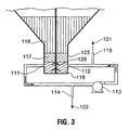
- Figure 3 shows a cross section of a portion of a reservoir 125 containing various layers of mud 116, 117 and 118 and having two openings, one being a suction point 111 (mud outlet) and the other one being a discharge point 112 (mud inlet) and is equipped with a low shear stirrer 126.
- This reservoir 125 differs from the one in Figure 2 in that the bottom section is a truncated inverted cone with a cylindrical portion at its lower end.
- the system essentially operates in the same manner as the one described in Figure 1 with the added presence of the low shear stirrer 126 which further reduces the viscosity of the mud in the region located between the suction point 111 and the discharge point 112.
- the solids concentration at the underflow of the thickener reached approximately 53% by weight and the yield stress was of the order of 400 Pa.
- This mud was difficult and impractical to remove from the base of the thickener and the suction side of a positive displacement pump located a few meters away could not be adequately fed.
- the yield stress measured in the re-circulation loop was reduced to 100-120 Pa and the material could be continuously withdrawn from the thickener.
- the positive displacement pump fed with this remolded mud operated without difficulty. All yield stress measurements were carried out by rotary viscometry.
- a thickener vessel used to settle red mud of a composition similar to the one described in Example 1 above was limited to an underflow concentration of 38 to 40% solids for consistent operation and to avoid frequent blockages of the outlet of the thickener.
- a recirculation system was installed on the vessel and the unit was able to operate without interruption at concentration of the order of 52 to 55% solids.
- the test was repeated again with fresh slurry of the same initial concentration but this time, as the mud was let to settle, the underflow flow pump and the in-line agitator were started and the slurry was re-injected at the base of the cylinder containing the slurry.
- the solids after few hours of settling achieved a concentration 54.7% and the yield stress measured on this remolded slurry was 48 Pa.
- the mud contained in the cylinder was then completely removed through a branched pipe attached to the conduit recirculating the mud back to the base of the cylinder
- red mud which is the residue of the digestion of bauxite
- the same basic principle has been applied to other residues such as copper and various calcium salts with similar results.
- the percentage solids in the slurry will vary with the nature of the mud, the method of this invention will greatly improve the transfer of virtually any thick slurry out of a reservoir when the slurry has a shear thinning visco-plastic behavior and, preferably, the initial yield stress of the slurry is not above about 500 Pa. This is the case for mining residues such as zinc, gold, iron ore or platinum tailings and tar sands residues to name a few that have been tested for their rheological properties.
- a copper tailing slurry was fed to a high capacity deep thickener.
- the solids concentration measured was approximately 68% solids by weight and yield stress was such that the tailing slurry would not flow by gravity from the thickener to a floor trench.
- the yield stress was measured in the field using a modified version of the cement slump test using a cylinder 100 mm in diameter by 200 mm in height. In a slump test, the larger the diameter measured, the less viscous the material. In terms of yield stress this would translate into a lower yield stress for higher slump value.
- the measured slump from the thickener was 130 mm. By using a recirculation system such as the one illustrated in Figure 2, the "slump" was reduced to 165 mm and the slurry could be discharged through a controlled valve into the floor trench and to a disposal site nearby.
Landscapes
- Chemical & Material Sciences (AREA)
- Chemical Kinetics & Catalysis (AREA)
- Mixers Of The Rotary Stirring Type (AREA)
- Treatment Of Sludge (AREA)
- Reciprocating Pumps (AREA)
- Preparation Of Compounds By Using Micro-Organisms (AREA)
- Liquid Crystal Substances (AREA)
- Preparation Of Clay, And Manufacture Of Mixtures Containing Clay Or Cement (AREA)
- Pharmaceuticals Containing Other Organic And Inorganic Compounds (AREA)
- Fats And Perfumes (AREA)
- Saccharide Compounds (AREA)
- Pipeline Systems (AREA)
- Separation Of Solids By Using Liquids Or Pneumatic Power (AREA)
- Compositions Of Macromolecular Compounds (AREA)
- Inks, Pencil-Leads, Or Crayons (AREA)
- Conductive Materials (AREA)
Claims (28)
- Verfahren zum Abziehen einer Aufschlämmung, welche die Scherung verdünnende, viskoplastische Eigenschaften aufweist, aus einem Vorratsbehälter (10), der eine Masse aus der Aufschlämmung (16, 17) enthält, wobei die Aufschlämmung eine derartig hohe Viskosität aufweist, dass ein direktes Abziehen eines Flusses der Aufschlämmung auf den Vorratsbehälter schwierig ist, gekennzeichnet durch:Erzeugen eines untergetauchten Bereiches einer in der Scherung verdünnten Aufschlämmung mit verringerter Viskosität (18) in der Masse der Aufschlämmung unterhalb der Aufschlämmung mit hoher Viskosität (16, 17) zum Mitnehmen benachbarter Aufschlämmung mit hoher Viskosität durch temporäres Abziehen von Aufschlämmung von dem unteren Teil des Vorratsbehälters (10) über einen Auslass (11) zur Ausbildung eines Flusses abgezogener Aufschlämmung (19), Einwirken lassen einer Scherung (13) auf die abgezogene Aufschlämmung zur Erzeugung eines Flusses einer Aufschlämmung mit verringerter Scherung und verringerter Viskosität (20), und Rückführen der Aufschlämmung mit verringerter Scherung mit verringerter Viskosität (20) zu dem Vorratsbehälter (10) über einen Einlass (12), der von dem Auslass (11) beabstandet ist, wodurch ein Fluss der Aufschlämmung zwischen dem Einlass und dem Auslass erzeugt wird, der dazu ausreicht, einen Anteil der Aufschlämmung mit hoher Viskosität mitzunehmen; undAbziehen eines Anteils der Aufschlämmung mit verringerter Viskosität, der mitgenommene Aufschlämmung mit hoher Viskosität (21, 22) enthält, von dem Vorratsbehälter (10).
- Verfahren nach Anspruch 1, dadurch gekennzeichnet, dass der Auslass (11) und der Einlass (12) voneinander um eine Entfernung innerhalb des Bereiches von 0,2 bis 10 m beabstandet sind.
- Verfahren nach Anspruch 1 oder Anspruch 2, dadurch gekennzeichnet, dass die Scherung, welcher die abgezogenen Aufschlämmung ausgesetzt ist, im Bereich von 50 bis 1000 Pa liegt.
- Verfahren nach Anspruch 1, dadurch gekennzeichnet, dass der Anteil der Aufschlämmung mit verringerter Viskosität endgültig von dem Vorratsbehälter direkt von dem untergetauchten Bereich in der Masse der Aufschlämmung abgezogen wird.
- Verfahren nach Anspruch 1, Anspruch 2 oder Anspruch 3, dadurch gekennzeichnet, dass ein Anteil der Aufschlämmung mit verringerter Scherung, der von dem Auslass (11) abgezogen wird, nicht erneut in den Vorratsbehälter (10) über den Einlass (12) eingegeben wird, so dass er endgültig von dem Vorratsbehälter (10) entfernt wird.
- Verfahren nach Anspruch 5, dadurch gekennzeichnet, dass das Verhältnis einer Volumenmenge der Aufschlämmung, die zum Vorratsbehälter (10) über den Einlass (12) umgewälzt wird, zu einer Nettomenge der Aufschlämmung, die endgültig von dem Vorratsbehälter abgezogen wird, im Bereich von 0,25 bis 10:1 liegt.
- Verfahren nach Anspruch 1, Anspruch 2 oder Anspruch 3, dadurch gekennzeichnet, dass der Anteil der Aufschlämmung mit verringerter Viskosität (21) von dem Fluss der abgezogenen Aufschlämmung entfernt wird, bevor der Fluss der abgezogenen Aufschlämmung der Scherung ausgesetzt wird.
- Verfahren nach Anspruch 1, Anspruch 2 oder Anspruch 3, dadurch gekennzeichnet, dass der Anteil der Aufschlämmung mit verringerter Viskosität (22) von dem Fluss der Aufschlämmung mit verringerter Scherung abgezogen wird, bevor der Fluss der Aufschlämmung mit verringerter Scherung zu dem eingetauchten Bereich über den Einlass (12) zurückgeführt wird.
- Verfahren nach einem der Ansprüche 1 bis 8, dadurch gekennzeichnet, dass die Aufschlämmung mit verringerter Scherung und verringerter Viskosität eine Fließgrenze im Bereich von 50 bis weniger als 500 Pa aufweist.
- Verfahren nach einem der Ansprüche 1 bis 9, dadurch gekennzeichnet, dass die Aufschlämmung in dem untergetauchten Bereich (18) gerührt wird (26).
- Verfahren nach Anspruch 10, dadurch gekennzeichnet, dass die Aufschlämmung durch eine sich drehende Vorrichtung (26) im Bereich von 0,05 bis 5 Umdrehungen pro Minute gerührt wird.
- Verfahren nach einem der Ansprüche 1 bis 11, dadurch gekennzeichnet, dass der untergetauchte Bereich (18) der Masse ein Bereich in der Nähe eines unteren Endes des Vorratsbehälters (10) ist.
- Verfahren nach einem der Ansprüche 1 bis 12, dadurch gekennzeichnet, dass der Vorratsbehälter (10) als eine Aufschlämmungsverdickungsvorrichtung wirkt, um einen Feststoffgehalt der Aufschlämmung zu erhöhen, die in den Vorratsbehälter eingegeben wird, wenn sich die Aufschlämmung durch den Vorratsbehälter zu einem unteren Ende des Vorratsbehälters bewegt, wobei der Strom der Aufschlämmung mit verringerter Scherung und verringerter Viskosität in dem untergetauchten Bereich erzeugt wird, der in der Nähe des unteren Endes des Vorratsbehälters liegt.
- Verfahren nach Anspruch 13, dadurch gekennzeichnet, dass die Aufschlämmungsverdickungsvorrichtung kontinuierlich einwirkt, und der Anteil der Aufschlämmung mit verringerter Viskosität kontinuierlich von dem Vorratsbehälter abgezogen wird.
- Verfahren nach einem der Ansprüche 1 bis 14, dadurch gekennzeichnet, dass die Masse der Aufschlämmung unter Druck gesetzt wird.
- Verfahren nach einem der Ansprüche 1 bis 15, dadurch gekennzeichnet, dass die Aufschlämmung eine Fließgrenze von bis zu 500 Pa außerhalb des Bereiches mit verringerter Viskosität aufweist.
- Verfahren nach einem der Ansprüche 1 bis 16, dadurch gekennzeichnet, dass der Vorratsbehälter dazu eingesetzt wird, eine Aufschlämmung mittels Schwerkraft zu verdicken, und der Bereich der Aufschlämmung mit verringerter Scherung sofort ausgebildet wird, wenn mit der Verdickung mittels Schwerkraft begonnen wird.
- Verfahren nach einem der Ansprüche 1 bis 17, dadurch gekennzeichnet, dass der Anteil der Aufschlämmung mit verringerter Viskosität, der von dem Vorratsbehälter abgezogen wird, einen gewissen Anteil der benachbarten Aufschlämmung mitnimmt.
- Einrichtung zum Halten und Liefern einer Aufschlämmung mit einer derartigen Viskosität, dass ein direktes Abziehen eines Flusses der Aufschlämmung aus einem Vorratsbehälter (10), der eine Masse der Aufschlämmung enthält, schwierig ist, wobei die Einrichtung einen Vorratsbehälter zum Enthalten einer Masse der Aufschlämmung (16, 17), eine Vorrichtung zum Einführen der Aufschlämmung in einen oberen Bereich des Vorratsbehälters (10), sowie einen Auslass (11) zum Abziehen von Aufschlämmung aus einem unteren Bereich des Vorratsbehälters (10),
dadurch gekennzeichnet, dass die Einrichtung weiterhin aufweist:einen Scherungserzeuger (13) zur Erzeugung eines untergetauchten Bereiches einer Aufschlämmung mit verringerter Viskosität (18) in der Masse unterhalb der Aufschlämmung mit hoher Viskosität (16, 17) zum Mitnehmen benachbarter Aufschlämmung mit der hohen Viskosität,eine erste Leitung (19), die an den Vorratsbehälterauslass (11) angeschlossen ist, um Aufschlämmung von dem untergetauchten Bereich (18) abzuziehen, wobei die Erzeugungsvorrichtung (13) mit der ersten Leitung (19) in Verbindung steht, um abgezogene Aufschlämmung von der ersten Leitung (19) einer Scherung auszusetzen, sowie eine zweite Leitung (20), die mit der Scherungserzeugungsvorrichtung (13) verbunden ist, und eine Verbindung zum Einlass (12) in dem Vorratsbehälter (10) herstellt, um die Aufschlämmung mit verringerter Scherung und verringerter Viskosität von der Scherungserzeugungsvorrichtung (13) zurückzuführen, zu dem untergetauchten Bereich (18) der Masse, wobei der Auslass (11) und der Einlass (12) voneinander in dem Bereich beabstandet sind, um hierdurch den Fluss der Aufschlämmung zwischen dem Einlass und dem Auslass zu erzeugen, der dazu ausreicht, einen Anteil der Aufschlämmung mit hoher Viskosität (16, 17) mitzunehmen. - Einrichtung nach Anspruch 19, dadurch gekennzeichnet, dass die Aufschlämmungsabzugsvorrichtung eine dritte Leitung aufweist, die einen Einlass in dem Vorratsbehälter (10) in der Nähe des untergetauchten Bereichs (18) aufweist.
- Einrichtung nach Anspruch 19, dadurch gekennzeichnet, dass die Aufschlämmungsabzugsvorrichtung eine dritte Leitung (14) aufweist, die mit der ersten Leitung (19) in Verbindung steht.
- Einrichtung nach Anspruch 19, dadurch gekennzeichnet, dass die Aufschlämmungsabzugsvorrichtung eine dritte Leitung (15) aufweist, die mit der zweiten Leitung (20) in Verbindung steht.
- Einrichtung nach Anspruch 19, dadurch gekennzeichnet, dass die Scherungserzeugungsvorrichtung eine Fluidpumpe (13) ist.
- Einrichtung nach Anspruch 19, dadurch gekennzeichnet, dass eine Fördervorrichtung vorgesehen ist, um von dem Vorratsbehälter den Anteil der Aufschlämmung wegzufördern, der von ihm abgezogen wird.
- Einrichtung nach Anspruch 24, dadurch gekennzeichnet, dass die Scherungserzeugungsvorrichtung (13) als die Fördervorrichtung dient.
- Einrichtung nach einem der Ansprüche 19 bis 25, welche weiterhin eine Aufschlämmungsrührvorrichtung (28) aufweist, die in dem Vorratsbehälter (10) in dem untergetauchten Bereich (18) angeordnet ist.
- Einrichtung nach einem der Ansprüche 19 bis 26, dadurch gekennzeichnet, dass der Vorratsbehälter (10) dazu ausgebildet ist, als eine Aufschlämmungsverdickungsvorrichtung zu arbeiten.
- Einrichtung nach einem der Ansprüche 19 bis 27, dadurch gekennzeichnet, dass sie eine Druckaufbringungsvorrichtung zur Druckbeaufschlagung der Masse der Aufschlämmung aufweist.
Applications Claiming Priority (3)
| Application Number | Priority Date | Filing Date | Title |
|---|---|---|---|
| US268276 | 1999-03-15 | ||
| US09/268,276 US6340033B2 (en) | 1999-03-15 | 1999-03-15 | Transfer of shear-thinning slurries |
| PCT/CA2000/000293 WO2000054870A1 (en) | 1999-03-15 | 2000-03-15 | Transfer of shear-thinning slurries |
Publications (2)
| Publication Number | Publication Date |
|---|---|
| EP1165202A1 EP1165202A1 (de) | 2002-01-02 |
| EP1165202B1 true EP1165202B1 (de) | 2004-06-02 |
Family
ID=23022235
Family Applications (1)
| Application Number | Title | Priority Date | Filing Date |
|---|---|---|---|
| EP00910467A Expired - Lifetime EP1165202B1 (de) | 1999-03-15 | 2000-03-15 | Förderung scherverdünnter aufschlämmungen |
Country Status (12)
| Country | Link |
|---|---|
| US (1) | US6340033B2 (de) |
| EP (1) | EP1165202B1 (de) |
| CN (1) | CN1188200C (de) |
| AT (1) | ATE268201T1 (de) |
| AU (1) | AU757084C (de) |
| BR (1) | BR0009067B1 (de) |
| CA (1) | CA2367551C (de) |
| DE (1) | DE60011252T2 (de) |
| OA (1) | OA11846A (de) |
| PT (1) | PT1165202E (de) |
| WO (1) | WO2000054870A1 (de) |
| ZA (1) | ZA200107350B (de) |
Cited By (1)
| Publication number | Priority date | Publication date | Assignee | Title |
|---|---|---|---|---|
| US7473376B2 (en) | 2005-08-23 | 2009-01-06 | Alcan International Limited | Apparatus for production, withdrawal and transfer of highly viscous slurry |
Families Citing this family (21)
| Publication number | Priority date | Publication date | Assignee | Title |
|---|---|---|---|---|
| FI116889B (fi) * | 2004-03-03 | 2006-03-31 | Outokumpu Oy | Laite kiintoainetta sisältävän materiaalin hierto-ohentamiseksi |
| FR2875495B1 (fr) * | 2004-09-21 | 2006-10-27 | Aluminium Pechiney Soc Par Act | Perfectionnement au procede bayer de fabrication de trihydrate d'alumine, ledit perfectionnement portant sur la separation de la liqueur d'aluminate et des residus insolubles |
| FI20041519L (fi) * | 2004-11-26 | 2006-05-27 | Outokumpu Oy | Menetelmä ja laite sakeuttimen pohjavirran konsentroimiseksi |
| FI118519B (fi) * | 2006-04-28 | 2007-12-14 | Outotec Oyj | Menetelmä ja laite kiintoaineita sisältävän materiaalin hierto-ohentamiseksi |
| US8328409B2 (en) * | 2006-05-11 | 2012-12-11 | Rineco Chemical Industries, Inc. | Method and device for agitation of tank-stored material |
| CN101235940B (zh) * | 2007-06-22 | 2011-05-25 | 浙江科技学院科技开发中心 | 表面膜减阻方法与粘塑性物料管道输送技术 |
| US7575365B2 (en) * | 2007-10-26 | 2009-08-18 | Uop Llc | Viscosity control of particle formation by adjusting agitation speed |
| CN101468262B (zh) * | 2007-12-25 | 2010-12-01 | 中国恩菲工程技术有限公司 | 深锥浓密机 |
| RU2503481C2 (ru) * | 2008-09-17 | 2014-01-10 | Ототек Оюй | Способ регулирования возмущения шлама с сетчатой структурой |
| US9376305B2 (en) | 2011-06-22 | 2016-06-28 | Allpure Technologies, Inc. | Fluid transfer interface |
| US10773863B2 (en) | 2011-06-22 | 2020-09-15 | Sartorius Stedim North America Inc. | Vessel closures and methods for using and manufacturing same |
| EP2723647B1 (de) | 2011-06-22 | 2018-05-09 | Sartorius Stedim North America Inc. | Behälterverschlüsse sowie verfahren zu ihrer verwendung und herstellung |
| WO2013140330A1 (en) * | 2012-03-19 | 2013-09-26 | Delkor Technik B.V. | Shear-thinning of slurries |
| EP3077324A4 (de) | 2013-12-06 | 2017-08-02 | Allpure Technologies, Inc. | Fluidübertragungsschnittstelle |
| US11577953B2 (en) | 2017-11-14 | 2023-02-14 | Sartorius Stedim North America, Inc. | System for simultaneous distribution of fluid to multiple vessels and method of using the same |
| US12252391B2 (en) | 2017-11-14 | 2025-03-18 | Sartorius Stedim North America Inc. | System for simultaneous distribution of fluid to multiple vessels and method of using the same |
| US11691866B2 (en) | 2017-11-14 | 2023-07-04 | Sartorius Stedim North America Inc. | System for simultaneous distribution of fluid to multiple vessels and method of using the same |
| US11319201B2 (en) | 2019-07-23 | 2022-05-03 | Sartorius Stedim North America Inc. | System for simultaneous filling of multiple containers |
| CN111379588B (zh) * | 2020-04-10 | 2024-07-12 | 昆明理工大学 | 一种基于低频脉冲的矿山充填料浆沉降离析控制系统与方法 |
| US12239127B2 (en) | 2021-07-28 | 2025-03-04 | Sartorius Stedim North America Inc. | Thermal capacitors, systems, and methods for rapid freezing or heating of biological materials |
| CN113908594A (zh) * | 2021-10-12 | 2022-01-11 | 怀化辰州机械有限责任公司 | 一种尾矿浆沉淀分离及再造方法 |
Family Cites Families (19)
| Publication number | Priority date | Publication date | Assignee | Title |
|---|---|---|---|---|
| US3685654A (en) | 1971-03-22 | 1972-08-22 | Gordon Sherritt Mines Ltd | Thickener |
| US3881654A (en) * | 1972-04-17 | 1975-05-06 | Gates Rubber Co | Battery paste pumping and metering system |
| US3776525A (en) | 1973-03-26 | 1973-12-04 | J Warner | Injection process |
| AU502936B2 (en) | 1975-01-24 | 1979-08-16 | Alcan Research And Development Limited | Flocculant control in sedimentation |
| GB2057166B (en) * | 1979-08-24 | 1983-06-02 | Wimpey Lab Ltd | Slurry-producing apparatus |
| US4471916A (en) | 1982-08-30 | 1984-09-18 | Chemfix Technologies, Inc. | Apparatus for treating liquid and semi-solid organic waste materials |
| US4579563A (en) | 1985-04-15 | 1986-04-01 | Burnside Kenneth D | Method and apparatus for fluidizing coal tar sludge |
| US4684551A (en) * | 1986-02-06 | 1987-08-04 | E. I. Du Pont De Nemours And Company | Thixotropic material coating apparatus, distributor device and method |
| CA1286480C (en) | 1986-02-28 | 1991-07-23 | Peter F. Bagatto | Method of and apparatus for thickening red muds derived from bauxite and similar slurries |
| US5080803A (en) | 1989-10-13 | 1992-01-14 | Alcan International Limited | Process for decantation of suspensions |
| AU640564B2 (en) * | 1991-06-07 | 1993-08-26 | Boxall, John Robert | Industrial mixer |
| US5188740A (en) | 1991-12-02 | 1993-02-23 | Texaco Inc. | Process for producing pumpable fuel slurry of sewage sludge and low grade solid carbonaceous fuel |
| US5188739A (en) | 1991-12-02 | 1993-02-23 | Texaco Inc. | Disposal of sewage sludge |
| DE4201949C2 (de) | 1992-01-24 | 1994-12-01 | Steyr Daimler Puch Ag | Verfahren zum Spritzen von Lacken sowie Lackiervorrichtung zur Durchführung des Verfahrens |
| CA2087927C (en) * | 1992-03-06 | 2000-04-11 | Jimmy A. Demars | Fluid dispenser |
| US5407561A (en) | 1993-05-07 | 1995-04-18 | Alcan International Limited | Pressure decanter |
| US5485941A (en) * | 1994-06-30 | 1996-01-23 | Basf Corporation | Recirculation system and method for automated dosing apparatus |
| US5718510A (en) | 1995-02-28 | 1998-02-17 | Inco Limited | Paste production and storage apparatus |
| AU1843697A (en) | 1996-01-31 | 1997-08-22 | Baker Hughes Incorporated | High density thickener underflow withdrawal device |
-
1999
- 1999-03-15 US US09/268,276 patent/US6340033B2/en not_active Expired - Lifetime
-
2000
- 2000-03-15 WO PCT/CA2000/000293 patent/WO2000054870A1/en not_active Ceased
- 2000-03-15 OA OA1200100231A patent/OA11846A/en unknown
- 2000-03-15 AT AT00910467T patent/ATE268201T1/de not_active IP Right Cessation
- 2000-03-15 CN CNB008072698A patent/CN1188200C/zh not_active Expired - Lifetime
- 2000-03-15 BR BRPI0009067-0A patent/BR0009067B1/pt not_active IP Right Cessation
- 2000-03-15 DE DE2000611252 patent/DE60011252T2/de not_active Expired - Lifetime
- 2000-03-15 PT PT00910467T patent/PT1165202E/pt unknown
- 2000-03-15 EP EP00910467A patent/EP1165202B1/de not_active Expired - Lifetime
- 2000-03-15 AU AU32684/00A patent/AU757084C/en not_active Expired
- 2000-03-15 CA CA 2367551 patent/CA2367551C/en not_active Expired - Lifetime
-
2001
- 2001-09-05 ZA ZA200107350A patent/ZA200107350B/xx unknown
Cited By (1)
| Publication number | Priority date | Publication date | Assignee | Title |
|---|---|---|---|---|
| US7473376B2 (en) | 2005-08-23 | 2009-01-06 | Alcan International Limited | Apparatus for production, withdrawal and transfer of highly viscous slurry |
Also Published As
| Publication number | Publication date |
|---|---|
| AU757084C (en) | 2004-06-24 |
| CA2367551A1 (en) | 2000-09-21 |
| AU3268400A (en) | 2000-10-04 |
| DE60011252T2 (de) | 2005-06-23 |
| BR0009067A (pt) | 2001-12-18 |
| PT1165202E (pt) | 2004-10-29 |
| AU757084B2 (en) | 2003-01-30 |
| OA11846A (en) | 2005-08-23 |
| WO2000054870A1 (en) | 2000-09-21 |
| US6340033B2 (en) | 2002-01-22 |
| DE60011252D1 (de) | 2004-07-08 |
| CN1350474A (zh) | 2002-05-22 |
| ATE268201T1 (de) | 2004-06-15 |
| BR0009067B1 (pt) | 2010-04-06 |
| ZA200107350B (en) | 2003-02-26 |
| US20010017161A1 (en) | 2001-08-30 |
| CA2367551C (en) | 2005-08-30 |
| CN1188200C (zh) | 2005-02-09 |
| EP1165202A1 (de) | 2002-01-02 |
Similar Documents
| Publication | Publication Date | Title |
|---|---|---|
| EP1165202B1 (de) | Förderung scherverdünnter aufschlämmungen | |
| KR102406986B1 (ko) | 2회 연속 침전 처리장치 | |
| AU775564B2 (en) | Rheology modification of settled solids in mineral processing | |
| US20190233310A1 (en) | Acoustic mixing for flocculant addition to mineral suspensions | |
| CN1354693A (zh) | 用于钻进和挖掘领域的回收装置及相关的方法 | |
| CN106398743B (zh) | 一种石油焦输送脱水系统 | |
| CA2876794A1 (en) | Concentration of suspensions | |
| CN110482745A (zh) | 一种垃圾焚烧炉渣的污水处理系统及污水处理方法 | |
| JP5116327B2 (ja) | 建設汚泥減容化装置及び建設汚泥減容化方法 | |
| RU2330734C1 (ru) | Установка для переработки нефтезагрязненных почв, грунтов и нефтешламов | |
| JPH07265900A (ja) | スラッジ処理装置 | |
| CA2867026C (en) | Shear-thinning of slurries | |
| CN215905888U (zh) | 一种高效气浮设备 | |
| CN212406634U (zh) | 一种海洋钻井废弃物可移动处理系统 | |
| GB2088895A (en) | Neutralization and Removal of Acid Sludge from Pits | |
| MXPA01009188A (en) | Transfer of shear-thinning slurries | |
| CN214270628U (zh) | 一种集成化盾构机泥水分离系统 | |
| CN222848178U (zh) | 一种水基、油基钻屑一体化处理系统 | |
| CN216472362U (zh) | 压力式化学除油器 | |
| CN220520260U (zh) | 一种煤矿水重介速沉处理设备 | |
| CN113751215B (zh) | 一种餐厨垃圾除砂处理装置 | |
| CN209974592U (zh) | 一种油气废水污泥处理装置 | |
| CN118851373A (zh) | 盾构废浆处理系统及其处理方法 | |
| CN120079633A (zh) | 一种一体式飞灰水洗压滤罐、飞灰水洗系统及水洗方法 | |
| JP2008296163A (ja) | 凝集剤を使用した懸濁水の固液分離装置 |
Legal Events
| Date | Code | Title | Description |
|---|---|---|---|
| PUAI | Public reference made under article 153(3) epc to a published international application that has entered the european phase |
Free format text: ORIGINAL CODE: 0009012 |
|
| 17P | Request for examination filed |
Effective date: 20011010 |
|
| AK | Designated contracting states |
Kind code of ref document: A1 Designated state(s): AT BE CH CY DE DK ES FI FR GB GR IE IT LI LU MC NL PT SE |
|
| AX | Request for extension of the european patent |
Free format text: AL;LT;LV;MK;RO;SI |
|
| 17Q | First examination report despatched |
Effective date: 20020626 |
|
| GRAH | Despatch of communication of intention to grant a patent |
Free format text: ORIGINAL CODE: EPIDOS IGRA |
|
| GRAH | Despatch of communication of intention to grant a patent |
Free format text: ORIGINAL CODE: EPIDOS IGRA |
|
| GRAA | (expected) grant |
Free format text: ORIGINAL CODE: 0009210 |
|
| AK | Designated contracting states |
Kind code of ref document: B1 Designated state(s): AT BE CH CY DE DK ES FI FR GB GR IE IT LI LU MC NL PT SE |
|
| PG25 | Lapsed in a contracting state [announced via postgrant information from national office to epo] |
Ref country code: CH Free format text: LAPSE BECAUSE OF FAILURE TO SUBMIT A TRANSLATION OF THE DESCRIPTION OR TO PAY THE FEE WITHIN THE PRESCRIBED TIME-LIMIT Effective date: 20040602 Ref country code: AT Free format text: LAPSE BECAUSE OF FAILURE TO SUBMIT A TRANSLATION OF THE DESCRIPTION OR TO PAY THE FEE WITHIN THE PRESCRIBED TIME-LIMIT Effective date: 20040602 Ref country code: NL Free format text: LAPSE BECAUSE OF FAILURE TO SUBMIT A TRANSLATION OF THE DESCRIPTION OR TO PAY THE FEE WITHIN THE PRESCRIBED TIME-LIMIT Effective date: 20040602 Ref country code: LI Free format text: LAPSE BECAUSE OF FAILURE TO SUBMIT A TRANSLATION OF THE DESCRIPTION OR TO PAY THE FEE WITHIN THE PRESCRIBED TIME-LIMIT Effective date: 20040602 Ref country code: BE Free format text: LAPSE BECAUSE OF FAILURE TO SUBMIT A TRANSLATION OF THE DESCRIPTION OR TO PAY THE FEE WITHIN THE PRESCRIBED TIME-LIMIT Effective date: 20040602 |
|
| REG | Reference to a national code |
Ref country code: GB Ref legal event code: FG4D |
|
| REG | Reference to a national code |
Ref country code: SE Ref legal event code: TRGR |
|
| REG | Reference to a national code |
Ref country code: CH Ref legal event code: EP |
|
| REF | Corresponds to: |
Ref document number: 60011252 Country of ref document: DE Date of ref document: 20040708 Kind code of ref document: P |
|
| REG | Reference to a national code |
Ref country code: IE Ref legal event code: FG4D |
|
| PG25 | Lapsed in a contracting state [announced via postgrant information from national office to epo] |
Ref country code: DK Free format text: LAPSE BECAUSE OF FAILURE TO SUBMIT A TRANSLATION OF THE DESCRIPTION OR TO PAY THE FEE WITHIN THE PRESCRIBED TIME-LIMIT Effective date: 20040902 |
|
| PG25 | Lapsed in a contracting state [announced via postgrant information from national office to epo] |
Ref country code: ES Free format text: LAPSE BECAUSE OF FAILURE TO SUBMIT A TRANSLATION OF THE DESCRIPTION OR TO PAY THE FEE WITHIN THE PRESCRIBED TIME-LIMIT Effective date: 20040913 |
|
| REG | Reference to a national code |
Ref country code: GR Ref legal event code: EP Ref document number: 20040402717 Country of ref document: GR |
|
| REG | Reference to a national code |
Ref country code: PT Ref legal event code: SC4A Free format text: AVAILABILITY OF NATIONAL TRANSLATION Effective date: 20040826 |
|
| REG | Reference to a national code |
Ref country code: CH Ref legal event code: PL |
|
| NLV1 | Nl: lapsed or annulled due to failure to fulfill the requirements of art. 29p and 29m of the patents act | ||
| ET | Fr: translation filed | ||
| PLAQ | Examination of admissibility of opposition: information related to despatch of communication + time limit deleted |
Free format text: ORIGINAL CODE: EPIDOSDOPE2 |
|
| PLBQ | Unpublished change to opponent data |
Free format text: ORIGINAL CODE: EPIDOS OPPO |
|
| PLAQ | Examination of admissibility of opposition: information related to despatch of communication + time limit deleted |
Free format text: ORIGINAL CODE: EPIDOSDOPE2 |
|
| PLAR | Examination of admissibility of opposition: information related to receipt of reply deleted |
Free format text: ORIGINAL CODE: EPIDOSDOPE4 |
|
| PLBI | Opposition filed |
Free format text: ORIGINAL CODE: 0009260 |
|
| PLBQ | Unpublished change to opponent data |
Free format text: ORIGINAL CODE: EPIDOS OPPO |
|
| PG25 | Lapsed in a contracting state [announced via postgrant information from national office to epo] |
Ref country code: LU Free format text: LAPSE BECAUSE OF NON-PAYMENT OF DUE FEES Effective date: 20050315 Ref country code: CY Free format text: LAPSE BECAUSE OF FAILURE TO SUBMIT A TRANSLATION OF THE DESCRIPTION OR TO PAY THE FEE WITHIN THE PRESCRIBED TIME-LIMIT Effective date: 20050315 |
|
| PG25 | Lapsed in a contracting state [announced via postgrant information from national office to epo] |
Ref country code: MC Free format text: LAPSE BECAUSE OF NON-PAYMENT OF DUE FEES Effective date: 20050331 |
|
| PLAQ | Examination of admissibility of opposition: information related to despatch of communication + time limit deleted |
Free format text: ORIGINAL CODE: EPIDOSDOPE2 |
|
| PLAR | Examination of admissibility of opposition: information related to receipt of reply deleted |
Free format text: ORIGINAL CODE: EPIDOSDOPE4 |
|
| PLAX | Notice of opposition and request to file observation + time limit sent |
Free format text: ORIGINAL CODE: EPIDOSNOBS2 |
|
| PLBQ | Unpublished change to opponent data |
Free format text: ORIGINAL CODE: EPIDOS OPPO |
|
| PLAB | Opposition data, opponent's data or that of the opponent's representative modified |
Free format text: ORIGINAL CODE: 0009299OPPO |
|
| 26 | Opposition filed |
Opponent name: OUTOKUMPU OYJ Effective date: 20050302 |
|
| R26 | Opposition filed (corrected) |
Opponent name: OUTOKUMPU OYJ Effective date: 20050302 |
|
| PLAF | Information modified related to communication of a notice of opposition and request to file observations + time limit |
Free format text: ORIGINAL CODE: EPIDOSCOBS2 |
|
| PLAF | Information modified related to communication of a notice of opposition and request to file observations + time limit |
Free format text: ORIGINAL CODE: EPIDOSCOBS2 |
|
| PLBB | Reply of patent proprietor to notice(s) of opposition received |
Free format text: ORIGINAL CODE: EPIDOSNOBS3 |
|
| PLCK | Communication despatched that opposition was rejected |
Free format text: ORIGINAL CODE: EPIDOSNREJ1 |
|
| PLBN | Opposition rejected |
Free format text: ORIGINAL CODE: 0009273 |
|
| STAA | Information on the status of an ep patent application or granted ep patent |
Free format text: STATUS: OPPOSITION REJECTED |
|
| 27O | Opposition rejected |
Effective date: 20061223 |
|
| REG | Reference to a national code |
Ref country code: FR Ref legal event code: PLFP Year of fee payment: 17 |
|
| REG | Reference to a national code |
Ref country code: FR Ref legal event code: PLFP Year of fee payment: 18 |
|
| REG | Reference to a national code |
Ref country code: FR Ref legal event code: PLFP Year of fee payment: 19 |
|
| PGFP | Annual fee paid to national office [announced via postgrant information from national office to epo] |
Ref country code: FI Payment date: 20190327 Year of fee payment: 20 Ref country code: IT Payment date: 20190322 Year of fee payment: 20 Ref country code: FR Payment date: 20190325 Year of fee payment: 20 Ref country code: DE Payment date: 20190327 Year of fee payment: 20 Ref country code: IE Payment date: 20190327 Year of fee payment: 20 |
|
| PGFP | Annual fee paid to national office [announced via postgrant information from national office to epo] |
Ref country code: SE Payment date: 20190326 Year of fee payment: 20 Ref country code: GR Payment date: 20190327 Year of fee payment: 20 |
|
| PGFP | Annual fee paid to national office [announced via postgrant information from national office to epo] |
Ref country code: PT Payment date: 20190222 Year of fee payment: 20 |
|
| PGFP | Annual fee paid to national office [announced via postgrant information from national office to epo] |
Ref country code: GB Payment date: 20190404 Year of fee payment: 20 |
|
| REG | Reference to a national code |
Ref country code: DE Ref legal event code: R071 Ref document number: 60011252 Country of ref document: DE |
|
| REG | Reference to a national code |
Ref country code: GB Ref legal event code: PE20 Expiry date: 20200314 |
|
| REG | Reference to a national code |
Ref country code: IE Ref legal event code: MK9A |
|
| PG25 | Lapsed in a contracting state [announced via postgrant information from national office to epo] |
Ref country code: GB Free format text: LAPSE BECAUSE OF EXPIRATION OF PROTECTION Effective date: 20200314 Ref country code: PT Free format text: LAPSE BECAUSE OF EXPIRATION OF PROTECTION Effective date: 20200326 |
|
| REG | Reference to a national code |
Ref country code: SE Ref legal event code: EUG |
|
| REG | Reference to a national code |
Ref country code: FI Ref legal event code: MAE |
|
| PG25 | Lapsed in a contracting state [announced via postgrant information from national office to epo] |
Ref country code: IE Free format text: LAPSE BECAUSE OF EXPIRATION OF PROTECTION Effective date: 20200315 |