EP1165227B1 - Reacteur a microcolonnes - Google Patents
Reacteur a microcolonnes Download PDFInfo
- Publication number
- EP1165227B1 EP1165227B1 EP00920456A EP00920456A EP1165227B1 EP 1165227 B1 EP1165227 B1 EP 1165227B1 EP 00920456 A EP00920456 A EP 00920456A EP 00920456 A EP00920456 A EP 00920456A EP 1165227 B1 EP1165227 B1 EP 1165227B1
- Authority
- EP
- European Patent Office
- Prior art keywords
- channel
- microcolumn
- passage openings
- wafer
- openings
- Prior art date
- Legal status (The legal status is an assumption and is not a legal conclusion. Google has not performed a legal analysis and makes no representation as to the accuracy of the status listed.)
- Expired - Lifetime
Links
- 239000000758 substrate Substances 0.000 claims abstract description 53
- 239000012528 membrane Substances 0.000 claims abstract description 20
- 238000006243 chemical reaction Methods 0.000 claims abstract description 15
- 239000011325 microbead Substances 0.000 claims abstract description 13
- 239000007790 solid phase Substances 0.000 claims abstract description 9
- 239000012530 fluid Substances 0.000 claims abstract description 7
- 235000012431 wafers Nutrition 0.000 claims abstract 28
- 239000011148 porous material Substances 0.000 claims description 14
- 239000011521 glass Substances 0.000 claims description 8
- 238000005530 etching Methods 0.000 claims description 7
- 238000004458 analytical method Methods 0.000 claims description 4
- 230000003287 optical effect Effects 0.000 claims description 4
- 229910052710 silicon Inorganic materials 0.000 claims description 4
- 239000010703 silicon Substances 0.000 claims description 4
- XUIMIQQOPSSXEZ-UHFFFAOYSA-N Silicon Chemical compound [Si] XUIMIQQOPSSXEZ-UHFFFAOYSA-N 0.000 claims description 3
- 239000011241 protective layer Substances 0.000 claims description 2
- 230000005540 biological transmission Effects 0.000 claims 4
- 230000013011 mating Effects 0.000 claims 3
- 239000010410 layer Substances 0.000 claims 2
- 230000000873 masking effect Effects 0.000 claims 2
- 239000011888 foil Substances 0.000 claims 1
- 229920002994 synthetic fiber Polymers 0.000 claims 1
- 230000005526 G1 to G0 transition Effects 0.000 abstract description 14
- 238000000034 method Methods 0.000 abstract description 14
- 239000012071 phase Substances 0.000 abstract description 13
- 238000003786 synthesis reaction Methods 0.000 abstract description 13
- 230000015572 biosynthetic process Effects 0.000 abstract description 12
- 238000000926 separation method Methods 0.000 abstract description 5
- 230000027455 binding Effects 0.000 abstract description 3
- 238000010828 elution Methods 0.000 abstract description 2
- RTZKZFJDLAIYFH-UHFFFAOYSA-N Diethyl ether Chemical compound CCOCC RTZKZFJDLAIYFH-UHFFFAOYSA-N 0.000 description 8
- 239000002245 particle Substances 0.000 description 7
- DHMQDGOQFOQNFH-UHFFFAOYSA-N Glycine Chemical compound NCC(O)=O DHMQDGOQFOQNFH-UHFFFAOYSA-N 0.000 description 6
- 239000011324 bead Substances 0.000 description 6
- 230000000712 assembly Effects 0.000 description 4
- 238000000429 assembly Methods 0.000 description 4
- 238000012216 screening Methods 0.000 description 4
- 239000000126 substance Substances 0.000 description 4
- 239000004471 Glycine Substances 0.000 description 3
- 235000001014 amino acid Nutrition 0.000 description 3
- 150000001413 amino acids Chemical class 0.000 description 3
- 238000005516 engineering process Methods 0.000 description 3
- 239000007788 liquid Substances 0.000 description 3
- 238000004519 manufacturing process Methods 0.000 description 3
- QOSSAOTZNIDXMA-UHFFFAOYSA-N Dicylcohexylcarbodiimide Chemical compound C1CCCCC1N=C=NC1CCCCC1 QOSSAOTZNIDXMA-UHFFFAOYSA-N 0.000 description 2
- 238000003747 Grignard reaction Methods 0.000 description 2
- KZSNJWFQEVHDMF-BYPYZUCNSA-N L-valine Chemical compound CC(C)[C@H](N)C(O)=O KZSNJWFQEVHDMF-BYPYZUCNSA-N 0.000 description 2
- DTQVDTLACAAQTR-UHFFFAOYSA-N Trifluoroacetic acid Chemical compound OC(=O)C(F)(F)F DTQVDTLACAAQTR-UHFFFAOYSA-N 0.000 description 2
- KZSNJWFQEVHDMF-UHFFFAOYSA-N Valine Natural products CC(C)C(N)C(O)=O KZSNJWFQEVHDMF-UHFFFAOYSA-N 0.000 description 2
- HRYZWHHZPQKTII-UHFFFAOYSA-N chloroethane Chemical compound CCCl HRYZWHHZPQKTII-UHFFFAOYSA-N 0.000 description 2
- 238000004140 cleaning Methods 0.000 description 2
- 229960003750 ethyl chloride Drugs 0.000 description 2
- 125000001495 ethyl group Chemical group [H]C([H])([H])C([H])([H])* 0.000 description 2
- 238000000605 extraction Methods 0.000 description 2
- 150000002902 organometallic compounds Chemical class 0.000 description 2
- 229920006254 polymer film Polymers 0.000 description 2
- 239000000725 suspension Substances 0.000 description 2
- 239000004474 valine Substances 0.000 description 2
- XLYOFNOQVPJJNP-UHFFFAOYSA-N water Substances O XLYOFNOQVPJJNP-UHFFFAOYSA-N 0.000 description 2
- 206010013786 Dry skin Diseases 0.000 description 1
- CCQOOWAONKGYKQ-BYPYZUCNSA-N Gly-Gly-Ala Chemical compound OC(=O)[C@H](C)NC(=O)CNC(=O)CN CCQOOWAONKGYKQ-BYPYZUCNSA-N 0.000 description 1
- XPJBQTCXPJNIFE-ZETCQYMHSA-N Gly-Gly-Leu Chemical compound CC(C)C[C@@H](C(O)=O)NC(=O)CNC(=O)CN XPJBQTCXPJNIFE-ZETCQYMHSA-N 0.000 description 1
- GWCJMBNBFYBQCV-XPUUQOCRSA-N Gly-Val-Ala Chemical compound NCC(=O)N[C@@H](C(C)C)C(=O)N[C@@H](C)C(O)=O GWCJMBNBFYBQCV-XPUUQOCRSA-N 0.000 description 1
- BAYQNCWLXIDLHX-ONGXEEELSA-N Gly-Val-Leu Chemical compound CC(C)C[C@@H](C(O)=O)NC(=O)[C@H](C(C)C)NC(=O)CN BAYQNCWLXIDLHX-ONGXEEELSA-N 0.000 description 1
- QNAYBMKLOCPYGJ-REOHCLBHSA-N L-alanine Chemical compound C[C@H](N)C(O)=O QNAYBMKLOCPYGJ-REOHCLBHSA-N 0.000 description 1
- ROHFNLRQFUQHCH-YFKPBYRVSA-N L-leucine Chemical compound CC(C)C[C@H](N)C(O)=O ROHFNLRQFUQHCH-YFKPBYRVSA-N 0.000 description 1
- ROHFNLRQFUQHCH-UHFFFAOYSA-N Leucine Natural products CC(C)CC(N)C(O)=O ROHFNLRQFUQHCH-UHFFFAOYSA-N 0.000 description 1
- FYYHWMGAXLPEAU-UHFFFAOYSA-N Magnesium Chemical compound [Mg] FYYHWMGAXLPEAU-UHFFFAOYSA-N 0.000 description 1
- 108091034117 Oligonucleotide Proteins 0.000 description 1
- 239000004793 Polystyrene Substances 0.000 description 1
- JLCPHMBAVCMARE-UHFFFAOYSA-N [3-[[3-[[3-[[3-[[3-[[3-[[3-[[3-[[3-[[3-[[3-[[5-(2-amino-6-oxo-1H-purin-9-yl)-3-[[3-[[3-[[3-[[3-[[3-[[5-(2-amino-6-oxo-1H-purin-9-yl)-3-[[5-(2-amino-6-oxo-1H-purin-9-yl)-3-hydroxyoxolan-2-yl]methoxy-hydroxyphosphoryl]oxyoxolan-2-yl]methoxy-hydroxyphosphoryl]oxy-5-(5-methyl-2,4-dioxopyrimidin-1-yl)oxolan-2-yl]methoxy-hydroxyphosphoryl]oxy-5-(6-aminopurin-9-yl)oxolan-2-yl]methoxy-hydroxyphosphoryl]oxy-5-(6-aminopurin-9-yl)oxolan-2-yl]methoxy-hydroxyphosphoryl]oxy-5-(6-aminopurin-9-yl)oxolan-2-yl]methoxy-hydroxyphosphoryl]oxy-5-(6-aminopurin-9-yl)oxolan-2-yl]methoxy-hydroxyphosphoryl]oxyoxolan-2-yl]methoxy-hydroxyphosphoryl]oxy-5-(5-methyl-2,4-dioxopyrimidin-1-yl)oxolan-2-yl]methoxy-hydroxyphosphoryl]oxy-5-(4-amino-2-oxopyrimidin-1-yl)oxolan-2-yl]methoxy-hydroxyphosphoryl]oxy-5-(5-methyl-2,4-dioxopyrimidin-1-yl)oxolan-2-yl]methoxy-hydroxyphosphoryl]oxy-5-(5-methyl-2,4-dioxopyrimidin-1-yl)oxolan-2-yl]methoxy-hydroxyphosphoryl]oxy-5-(6-aminopurin-9-yl)oxolan-2-yl]methoxy-hydroxyphosphoryl]oxy-5-(6-aminopurin-9-yl)oxolan-2-yl]methoxy-hydroxyphosphoryl]oxy-5-(4-amino-2-oxopyrimidin-1-yl)oxolan-2-yl]methoxy-hydroxyphosphoryl]oxy-5-(4-amino-2-oxopyrimidin-1-yl)oxolan-2-yl]methoxy-hydroxyphosphoryl]oxy-5-(4-amino-2-oxopyrimidin-1-yl)oxolan-2-yl]methoxy-hydroxyphosphoryl]oxy-5-(6-aminopurin-9-yl)oxolan-2-yl]methoxy-hydroxyphosphoryl]oxy-5-(4-amino-2-oxopyrimidin-1-yl)oxolan-2-yl]methyl [5-(6-aminopurin-9-yl)-2-(hydroxymethyl)oxolan-3-yl] hydrogen phosphate Polymers Cc1cn(C2CC(OP(O)(=O)OCC3OC(CC3OP(O)(=O)OCC3OC(CC3O)n3cnc4c3nc(N)[nH]c4=O)n3cnc4c3nc(N)[nH]c4=O)C(COP(O)(=O)OC3CC(OC3COP(O)(=O)OC3CC(OC3COP(O)(=O)OC3CC(OC3COP(O)(=O)OC3CC(OC3COP(O)(=O)OC3CC(OC3COP(O)(=O)OC3CC(OC3COP(O)(=O)OC3CC(OC3COP(O)(=O)OC3CC(OC3COP(O)(=O)OC3CC(OC3COP(O)(=O)OC3CC(OC3COP(O)(=O)OC3CC(OC3COP(O)(=O)OC3CC(OC3COP(O)(=O)OC3CC(OC3COP(O)(=O)OC3CC(OC3COP(O)(=O)OC3CC(OC3COP(O)(=O)OC3CC(OC3COP(O)(=O)OC3CC(OC3CO)n3cnc4c(N)ncnc34)n3ccc(N)nc3=O)n3cnc4c(N)ncnc34)n3ccc(N)nc3=O)n3ccc(N)nc3=O)n3ccc(N)nc3=O)n3cnc4c(N)ncnc34)n3cnc4c(N)ncnc34)n3cc(C)c(=O)[nH]c3=O)n3cc(C)c(=O)[nH]c3=O)n3ccc(N)nc3=O)n3cc(C)c(=O)[nH]c3=O)n3cnc4c3nc(N)[nH]c4=O)n3cnc4c(N)ncnc34)n3cnc4c(N)ncnc34)n3cnc4c(N)ncnc34)n3cnc4c(N)ncnc34)O2)c(=O)[nH]c1=O JLCPHMBAVCMARE-UHFFFAOYSA-N 0.000 description 1
- 235000004279 alanine Nutrition 0.000 description 1
- 125000003277 amino group Chemical group 0.000 description 1
- QVGXLLKOCUKJST-UHFFFAOYSA-N atomic oxygen Chemical compound [O] QVGXLLKOCUKJST-UHFFFAOYSA-N 0.000 description 1
- 125000001797 benzyl group Chemical group [H]C1=C([H])C([H])=C(C([H])=C1[H])C([H])([H])* 0.000 description 1
- 230000000903 blocking effect Effects 0.000 description 1
- 238000004440 column chromatography Methods 0.000 description 1
- 239000002274 desiccant Substances 0.000 description 1
- 238000010586 diagram Methods 0.000 description 1
- 238000006073 displacement reaction Methods 0.000 description 1
- 238000009509 drug development Methods 0.000 description 1
- 238000001035 drying Methods 0.000 description 1
- 238000002523 gelfiltration Methods 0.000 description 1
- 108010026364 glycyl-glycyl-leucine Proteins 0.000 description 1
- 238000003780 insertion Methods 0.000 description 1
- 230000037431 insertion Effects 0.000 description 1
- 238000005342 ion exchange Methods 0.000 description 1
- 238000011068 loading method Methods 0.000 description 1
- 239000000463 material Substances 0.000 description 1
- 238000005259 measurement Methods 0.000 description 1
- 239000000203 mixture Substances 0.000 description 1
- 238000013021 overheating Methods 0.000 description 1
- 239000001301 oxygen Substances 0.000 description 1
- 229910052760 oxygen Inorganic materials 0.000 description 1
- 238000012856 packing Methods 0.000 description 1
- 238000005191 phase separation Methods 0.000 description 1
- 238000000206 photolithography Methods 0.000 description 1
- 239000004033 plastic Substances 0.000 description 1
- 229920000642 polymer Polymers 0.000 description 1
- 229920002223 polystyrene Polymers 0.000 description 1
- 108090000765 processed proteins & peptides Proteins 0.000 description 1
- 102000004196 processed proteins & peptides Human genes 0.000 description 1
- 238000012545 processing Methods 0.000 description 1
- 125000006239 protecting group Chemical group 0.000 description 1
- 239000000376 reactant Substances 0.000 description 1
- 230000000717 retained effect Effects 0.000 description 1
- 150000003376 silicon Chemical class 0.000 description 1
- 239000007787 solid Substances 0.000 description 1
- 238000010532 solid phase synthesis reaction Methods 0.000 description 1
- 239000002904 solvent Substances 0.000 description 1
- 238000001179 sorption measurement Methods 0.000 description 1
- 125000006850 spacer group Chemical group 0.000 description 1
- 230000009870 specific binding Effects 0.000 description 1
- 239000010409 thin film Substances 0.000 description 1
Images



Classifications
-
- G—PHYSICS
- G01—MEASURING; TESTING
- G01N—INVESTIGATING OR ANALYSING MATERIALS BY DETERMINING THEIR CHEMICAL OR PHYSICAL PROPERTIES
- G01N30/00—Investigating or analysing materials by separation into components using adsorption, absorption or similar phenomena or using ion-exchange, e.g. chromatography or field flow fractionation
- G01N30/02—Column chromatography
- G01N30/50—Conditioning of the sorbent material or stationary liquid
- G01N30/56—Packing methods or coating methods
-
- B—PERFORMING OPERATIONS; TRANSPORTING
- B01—PHYSICAL OR CHEMICAL PROCESSES OR APPARATUS IN GENERAL
- B01J—CHEMICAL OR PHYSICAL PROCESSES, e.g. CATALYSIS OR COLLOID CHEMISTRY; THEIR RELEVANT APPARATUS
- B01J19/00—Chemical, physical or physico-chemical processes in general; Their relevant apparatus
- B01J19/0046—Sequential or parallel reactions, e.g. for the synthesis of polypeptides or polynucleotides; Apparatus and devices for combinatorial chemistry or for making molecular arrays
-
- B—PERFORMING OPERATIONS; TRANSPORTING
- B01—PHYSICAL OR CHEMICAL PROCESSES OR APPARATUS IN GENERAL
- B01J—CHEMICAL OR PHYSICAL PROCESSES, e.g. CATALYSIS OR COLLOID CHEMISTRY; THEIR RELEVANT APPARATUS
- B01J19/00—Chemical, physical or physico-chemical processes in general; Their relevant apparatus
- B01J19/0093—Microreactors, e.g. miniaturised or microfabricated reactors
-
- B—PERFORMING OPERATIONS; TRANSPORTING
- B01—PHYSICAL OR CHEMICAL PROCESSES OR APPARATUS IN GENERAL
- B01J—CHEMICAL OR PHYSICAL PROCESSES, e.g. CATALYSIS OR COLLOID CHEMISTRY; THEIR RELEVANT APPARATUS
- B01J2219/00—Chemical, physical or physico-chemical processes in general; Their relevant apparatus
- B01J2219/00274—Sequential or parallel reactions; Apparatus and devices for combinatorial chemistry or for making arrays; Chemical library technology
- B01J2219/00277—Apparatus
- B01J2219/00279—Features relating to reactor vessels
- B01J2219/00306—Reactor vessels in a multiple arrangement
- B01J2219/00313—Reactor vessels in a multiple arrangement the reactor vessels being formed by arrays of wells in blocks
-
- B—PERFORMING OPERATIONS; TRANSPORTING
- B01—PHYSICAL OR CHEMICAL PROCESSES OR APPARATUS IN GENERAL
- B01J—CHEMICAL OR PHYSICAL PROCESSES, e.g. CATALYSIS OR COLLOID CHEMISTRY; THEIR RELEVANT APPARATUS
- B01J2219/00—Chemical, physical or physico-chemical processes in general; Their relevant apparatus
- B01J2219/00274—Sequential or parallel reactions; Apparatus and devices for combinatorial chemistry or for making arrays; Chemical library technology
- B01J2219/00277—Apparatus
- B01J2219/00351—Means for dispensing and evacuation of reagents
-
- B—PERFORMING OPERATIONS; TRANSPORTING
- B01—PHYSICAL OR CHEMICAL PROCESSES OR APPARATUS IN GENERAL
- B01J—CHEMICAL OR PHYSICAL PROCESSES, e.g. CATALYSIS OR COLLOID CHEMISTRY; THEIR RELEVANT APPARATUS
- B01J2219/00—Chemical, physical or physico-chemical processes in general; Their relevant apparatus
- B01J2219/00274—Sequential or parallel reactions; Apparatus and devices for combinatorial chemistry or for making arrays; Chemical library technology
- B01J2219/00277—Apparatus
- B01J2219/00351—Means for dispensing and evacuation of reagents
- B01J2219/00423—Means for dispensing and evacuation of reagents using filtration, e.g. through porous frits
-
- B—PERFORMING OPERATIONS; TRANSPORTING
- B01—PHYSICAL OR CHEMICAL PROCESSES OR APPARATUS IN GENERAL
- B01J—CHEMICAL OR PHYSICAL PROCESSES, e.g. CATALYSIS OR COLLOID CHEMISTRY; THEIR RELEVANT APPARATUS
- B01J2219/00—Chemical, physical or physico-chemical processes in general; Their relevant apparatus
- B01J2219/00274—Sequential or parallel reactions; Apparatus and devices for combinatorial chemistry or for making arrays; Chemical library technology
- B01J2219/00277—Apparatus
- B01J2219/00457—Dispensing or evacuation of the solid phase support
- B01J2219/00459—Beads
-
- B—PERFORMING OPERATIONS; TRANSPORTING
- B01—PHYSICAL OR CHEMICAL PROCESSES OR APPARATUS IN GENERAL
- B01J—CHEMICAL OR PHYSICAL PROCESSES, e.g. CATALYSIS OR COLLOID CHEMISTRY; THEIR RELEVANT APPARATUS
- B01J2219/00—Chemical, physical or physico-chemical processes in general; Their relevant apparatus
- B01J2219/00274—Sequential or parallel reactions; Apparatus and devices for combinatorial chemistry or for making arrays; Chemical library technology
- B01J2219/00277—Apparatus
- B01J2219/00497—Features relating to the solid phase supports
- B01J2219/005—Beads
-
- B—PERFORMING OPERATIONS; TRANSPORTING
- B01—PHYSICAL OR CHEMICAL PROCESSES OR APPARATUS IN GENERAL
- B01J—CHEMICAL OR PHYSICAL PROCESSES, e.g. CATALYSIS OR COLLOID CHEMISTRY; THEIR RELEVANT APPARATUS
- B01J2219/00—Chemical, physical or physico-chemical processes in general; Their relevant apparatus
- B01J2219/00274—Sequential or parallel reactions; Apparatus and devices for combinatorial chemistry or for making arrays; Chemical library technology
- B01J2219/00583—Features relative to the processes being carried out
- B01J2219/00585—Parallel processes
-
- B—PERFORMING OPERATIONS; TRANSPORTING
- B01—PHYSICAL OR CHEMICAL PROCESSES OR APPARATUS IN GENERAL
- B01J—CHEMICAL OR PHYSICAL PROCESSES, e.g. CATALYSIS OR COLLOID CHEMISTRY; THEIR RELEVANT APPARATUS
- B01J2219/00—Chemical, physical or physico-chemical processes in general; Their relevant apparatus
- B01J2219/00274—Sequential or parallel reactions; Apparatus and devices for combinatorial chemistry or for making arrays; Chemical library technology
- B01J2219/00583—Features relative to the processes being carried out
- B01J2219/00596—Solid-phase processes
-
- B—PERFORMING OPERATIONS; TRANSPORTING
- B01—PHYSICAL OR CHEMICAL PROCESSES OR APPARATUS IN GENERAL
- B01J—CHEMICAL OR PHYSICAL PROCESSES, e.g. CATALYSIS OR COLLOID CHEMISTRY; THEIR RELEVANT APPARATUS
- B01J2219/00—Chemical, physical or physico-chemical processes in general; Their relevant apparatus
- B01J2219/00781—Aspects relating to microreactors
- B01J2219/00783—Laminate assemblies, i.e. the reactor comprising a stack of plates
-
- B—PERFORMING OPERATIONS; TRANSPORTING
- B01—PHYSICAL OR CHEMICAL PROCESSES OR APPARATUS IN GENERAL
- B01J—CHEMICAL OR PHYSICAL PROCESSES, e.g. CATALYSIS OR COLLOID CHEMISTRY; THEIR RELEVANT APPARATUS
- B01J2219/00—Chemical, physical or physico-chemical processes in general; Their relevant apparatus
- B01J2219/00781—Aspects relating to microreactors
- B01J2219/00819—Materials of construction
- B01J2219/00824—Ceramic
- B01J2219/00828—Silicon wafers or plates
-
- B—PERFORMING OPERATIONS; TRANSPORTING
- B01—PHYSICAL OR CHEMICAL PROCESSES OR APPARATUS IN GENERAL
- B01J—CHEMICAL OR PHYSICAL PROCESSES, e.g. CATALYSIS OR COLLOID CHEMISTRY; THEIR RELEVANT APPARATUS
- B01J2219/00—Chemical, physical or physico-chemical processes in general; Their relevant apparatus
- B01J2219/00781—Aspects relating to microreactors
- B01J2219/00819—Materials of construction
- B01J2219/00833—Plastic
-
- B—PERFORMING OPERATIONS; TRANSPORTING
- B01—PHYSICAL OR CHEMICAL PROCESSES OR APPARATUS IN GENERAL
- B01J—CHEMICAL OR PHYSICAL PROCESSES, e.g. CATALYSIS OR COLLOID CHEMISTRY; THEIR RELEVANT APPARATUS
- B01J2219/00—Chemical, physical or physico-chemical processes in general; Their relevant apparatus
- B01J2219/00781—Aspects relating to microreactors
- B01J2219/00891—Feeding or evacuation
-
- B—PERFORMING OPERATIONS; TRANSPORTING
- B01—PHYSICAL OR CHEMICAL PROCESSES OR APPARATUS IN GENERAL
- B01J—CHEMICAL OR PHYSICAL PROCESSES, e.g. CATALYSIS OR COLLOID CHEMISTRY; THEIR RELEVANT APPARATUS
- B01J2219/00—Chemical, physical or physico-chemical processes in general; Their relevant apparatus
- B01J2219/00781—Aspects relating to microreactors
- B01J2219/00905—Separation
- B01J2219/00907—Separation using membranes
-
- B—PERFORMING OPERATIONS; TRANSPORTING
- B01—PHYSICAL OR CHEMICAL PROCESSES OR APPARATUS IN GENERAL
- B01J—CHEMICAL OR PHYSICAL PROCESSES, e.g. CATALYSIS OR COLLOID CHEMISTRY; THEIR RELEVANT APPARATUS
- B01J2219/00—Chemical, physical or physico-chemical processes in general; Their relevant apparatus
- B01J2219/00781—Aspects relating to microreactors
- B01J2219/0095—Control aspects
- B01J2219/00952—Sensing operations
-
- B—PERFORMING OPERATIONS; TRANSPORTING
- B01—PHYSICAL OR CHEMICAL PROCESSES OR APPARATUS IN GENERAL
- B01L—CHEMICAL OR PHYSICAL LABORATORY APPARATUS FOR GENERAL USE
- B01L3/00—Containers or dishes for laboratory use, e.g. laboratory glassware; Droppers
- B01L3/50—Containers for the purpose of retaining a material to be analysed, e.g. test tubes
- B01L3/502—Containers for the purpose of retaining a material to be analysed, e.g. test tubes with fluid transport, e.g. in multi-compartment structures
- B01L3/5027—Containers for the purpose of retaining a material to be analysed, e.g. test tubes with fluid transport, e.g. in multi-compartment structures by integrated microfluidic structures, i.e. dimensions of channels and chambers are such that surface tension forces are important, e.g. lab-on-a-chip
-
- C—CHEMISTRY; METALLURGY
- C40—COMBINATORIAL TECHNOLOGY
- C40B—COMBINATORIAL CHEMISTRY; LIBRARIES, e.g. CHEMICAL LIBRARIES
- C40B60/00—Apparatus specially adapted for use in combinatorial chemistry or with libraries
- C40B60/14—Apparatus specially adapted for use in combinatorial chemistry or with libraries for creating libraries
-
- G—PHYSICS
- G01—MEASURING; TESTING
- G01N—INVESTIGATING OR ANALYSING MATERIALS BY DETERMINING THEIR CHEMICAL OR PHYSICAL PROPERTIES
- G01N30/00—Investigating or analysing materials by separation into components using adsorption, absorption or similar phenomena or using ion-exchange, e.g. chromatography or field flow fractionation
- G01N30/02—Column chromatography
- G01N30/50—Conditioning of the sorbent material or stationary liquid
- G01N30/56—Packing methods or coating methods
- G01N2030/562—Packing methods or coating methods packing
- G01N2030/565—Packing methods or coating methods packing slurry packing
-
- G—PHYSICS
- G01—MEASURING; TESTING
- G01N—INVESTIGATING OR ANALYSING MATERIALS BY DETERMINING THEIR CHEMICAL OR PHYSICAL PROPERTIES
- G01N30/00—Investigating or analysing materials by separation into components using adsorption, absorption or similar phenomena or using ion-exchange, e.g. chromatography or field flow fractionation
- G01N30/02—Column chromatography
- G01N30/50—Conditioning of the sorbent material or stationary liquid
- G01N30/58—Conditioning of the sorbent material or stationary liquid the sorbent moving as a whole
-
- G—PHYSICS
- G01—MEASURING; TESTING
- G01N—INVESTIGATING OR ANALYSING MATERIALS BY DETERMINING THEIR CHEMICAL OR PHYSICAL PROPERTIES
- G01N30/00—Investigating or analysing materials by separation into components using adsorption, absorption or similar phenomena or using ion-exchange, e.g. chromatography or field flow fractionation
- G01N30/02—Column chromatography
- G01N30/60—Construction of the column
- G01N30/6095—Micromachined or nanomachined, e.g. micro- or nanosize
-
- Y—GENERAL TAGGING OF NEW TECHNOLOGICAL DEVELOPMENTS; GENERAL TAGGING OF CROSS-SECTIONAL TECHNOLOGIES SPANNING OVER SEVERAL SECTIONS OF THE IPC; TECHNICAL SUBJECTS COVERED BY FORMER USPC CROSS-REFERENCE ART COLLECTIONS [XRACs] AND DIGESTS
- Y10—TECHNICAL SUBJECTS COVERED BY FORMER USPC
- Y10T—TECHNICAL SUBJECTS COVERED BY FORMER US CLASSIFICATION
- Y10T436/00—Chemistry: analytical and immunological testing
- Y10T436/25—Chemistry: analytical and immunological testing including sample preparation
- Y10T436/2575—Volumetric liquid transfer
Definitions
- Sample particles (“Perlen”, “Beads”) have been used for decades Separation and synthesis used in the laboratory area. Usually, these are glass or polymer beads, which Diameters from 0.01 mm to 1 mm, typically around 0.1 mm, own and dry or pre-swollen as loose bulk in one Containers are filled and then rinsed with liquid, whereby between the solid phase surface of the particles and the surrounding one Liquid an adsorption or reaction process takes place.
- Procedure of Column chromatography e.g. gel filtration
- the column extraction the Immunodiagnostics
- biomolecule cleaning e.g. DNA cleaning
- homogeneous and heterogeneous synthesis of oligonucleotides, Peptides or combinatorial substance libraries
- the invention is based, for synthesis and Separation processes on small sample volumes, a micro column reactor too create, with the help of, instead of an alternating sequence of binding and Elution processes on one stationary during a series of operations integrated phase, an exchange of the stationary phase, e.g. to Loading, can take place around complex mixtures or also Separate particles and cells more efficiently and combinatorial syntheses to be easier and faster to carry out.
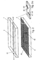
- the micro column reactor consists of two substrate plates 1, 2, wherein in the example in the first substrate plate 1, here consisting of glass, with the dimensions 15 mm * 8 mm * 1 mm, an elongated channel 3 is introduced, which has a width of 1 mm, a depth of 100 ⁇ m and a length of 10 mm is given.
- This channel is connected by two openings 61, 62, here bores, to two fluid connections, not shown.
- a silicon wafer with the dimensions 15 mm ⁇ 8 mm ⁇ 0.5 mm is selected in the example, into which two passage openings 41, 42 are incorporated in such a way that they capture a section a when positioned precisely relative to the glass plate 1, which in the example comes to lie over the end regions of the channel 3.
- the passage openings 41, 42 are spanned with a partially permeable sieve-like membrane, here in the form of a silicon oxynitride pore membrane.
- the thickness of the membrane is 2 ⁇ m and the passage areas 51 of the membrane have pores with diameters of 5 ⁇ m.
- the concrete sizes of the passage areas 51 can be variably specified.
- the membrane (5) serves to retain the particles or cells 7 to be introduced into the channel 3.
- the membrane (5) can be formed by a nanoporous thin-film membrane, the pore sizes of which are in a range between 5. 500 nm are fixed. If the through openings 41, 42 are to be given a structure as indicated in FIG. 3, in which the through openings are formed by two truncated pyramidal channel areas on their narrow base surfaces parallel to the surface normal n of the second substrate plate 2, the substrate plate 2 is used an Si (100) wafer, which is provided on both sides with a suitable etching mask (for example Si oxynitride).
- a suitable etching mask for example Si oxynitride
- This mask forms an array of micro windows on the front, the dimensions of which determine the pore size.
- a pore size of 5 ⁇ m is typically realized. This can be easily produced using conventional means of photolithography and etching technology.
- two windows are structured from the back of the Si wafer in such a way that two pyramid-shaped channels are formed on both sides during the etching, which are closed by sieve trays on their surface facing the first substrate plate 1.
- an Si is for the substrate plate -Wafer (in 100 orientation for inclined channel walls or in 110 orientation for vertical channel walls), which is provided with a sieve pore membrane mask structure 5, which in the region of the channel 411, 412 extending further through a channel corresponding to the channel width, which extends to the edge of the chip is sufficient, is accompanied (see Fig. 7a-d).
- the back of the Si wafer remains completely covered by an etch-resistant protective layer (eg Si 3 N 4 ).
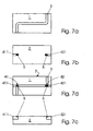
- FIGS. 7a-d show the result of the procedure described above using an exemplary structure.
- a channel 3 introduced into the first substrate plate 1 can be seen from FIG. 7a.
- FIG. 7b shows the structure introduced into the second substrate plate with the channel sections 411 and 421 extended to the substrate edge, FIG. 7c showing the relationships according to FIG. 7b in a lateral section and FIG.
- first and / or second Substrate plate 1, 2 a glass plate and / or a plate from one Plastic can be selected, the channel 3 in the first substrate plate 1 is introduced and the first substrate plate 1 facing Surface of the second substrate plate 2 continuously with one Membrane is covered, at least in the area of Through openings 41, 42 a microstructured perforation for Formation of the passage areas 51 is introduced.
- the second substrate plate 2 with a the substrate plate spanning perforated polymer film 50, as shown in Fig. 2 is indicated schematically. Even such an execution leaves other channel guides, as shown in Fig. 2a based on an example Channel guide 411, 421 in the substrate plate 2 is indicated.
- Figure 3 is a partial longitudinal section through one of the previously described Embodiments according to Fig. 1 or Fig. 2 shown. It is can be seen how the channel 3 in the assembled state of the Substrate plates 1, 2 with the solid phase, here in the form of microbeads 7 is filled. With this proposal it is not necessary to achieve extreme packing densities of the stationary phase 7. Important is only that the distances between the particles of the stationary phase 7th are so dimensioned that during the dwell time of a molecule in the Reactor space, including the one through the passage openings 41, 42 understood section of channel 3 is a sufficiently common Contact with the stationary phase takes place.
- Fig. 3 is also indicated schematically that the individual flow paths in the single micro column reactor shown Can be optionally closed by means of at least two valves 91, 92.
- the openings 42, 62 can also each have a further, 3 can be closed valve not shown.
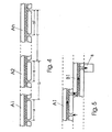
- FIGS. 4 and 5 possible arrangement forms are several Micro column reactors indicated schematically.
- the micro column reactors can be discrete, analogous to FIGS. 1 and 2, executed and related, or how shown in Figures 4 and 5, several such Micro-column reactors linear (Fig.4) each of a first and a second Be substrate platelet, or it can be several Micro column reactors in different levels (Fig. 5) with each other be connected, one level in each case analogously to FIG. 4 can be executed.
- the actual reactor sections determined by the length of the section a, through which the channel 3 through the passage openings 41, 42 is detected is, at an equidistant distance b or in a variable definable distance c can be arranged. It is also possible that Distances of the passage openings 41, 42 from reactor to reactor in determine their length differently, cf. Fig. 4, distances a and a1.
- the aforementioned options are only possible with the Micro column reactors determined reaction to be carried out. Further, in particular, also in microsystem technology, such as optical detectors, analysis units, calorimeters, electrochemical detectors etc., can be used in the interconnection several micro column reactors, as shown in FIG. 5 by such an assembly 8 is only indicated schematically.
- the proposed micro column reactor and its multiple use by interconnecting a number of individual micro column reactors is particularly suitable for carrying out automated processes for drug development by means of bead-bound solid phase synthesis.
- Several such micro-column reactors can also be interconnected with one another and by means of valves to be provided to form fluid logics in order, for example, to be able to carry out more complex combinatorial-chemical or screening operations in a micro-automated manner.
- cells can also be introduced into the system instead of the microbeads indicated in FIG.
- the reactor is also suitable for the micro-modular combination with micro flow cuvettes for microphotometric, microfluorimetric or microchemiluminometric measurements.
- the proposed micro column reactor allows new reaction partners (microbeads and / or cells) to be pushed through the channel 3 by applying a fluidic pressure p, so that there is further variability of the overall device with the lowest possible dead volume.
- microreactor fluid system a system with 16 microreactor columns is used, which are fluidly connected, as indicated in FIG. 6.
- the microreactors A1 and B1, as well as C1 and D1 are loaded with microbeads in the form of polystyrene synthetic beads, on the surface of which the amino acid glycine is coupled as a spacer via an ester bond to a benzyl group.
- the four micro-column reactors are paired (A / B) with a 1: 1 mixed warm solution of dicyclohexylcarbodiimide and valine, respectively, through the inlet and outlet of the channels for the mobile phases (C / D) with a 1: 1 mixed warm solution of dicyclohexylcarbodiimide and glycine.
- the amino groups of the amino acids supplied are protected by tertiary-butyloxycarbonyl groups.
- ethyl grignard from ethyl chloride for microfluidic synthesis
- a suspension of magnesium powder in dry ethyl ether is first introduced into a micro column reactor. After the channel has been blocked for this stationary phase, the ether is displaced by a warm solution of ethyl chloride in ether via the inlet and outlet for the mobile phase. At the end of the mobile phase, the ethyl grignard is removed as an ether solution.
- the micro column reactor can also be used for Provision of almost any Grignards and others organometallic compounds for microfluidic synthesis in chip format be used.
- the system is particularly advantageous because of the solutions can easily be kept free of water and oxygen (e.g. in the Contrary to microtiter plates and nanotiter plates) and due to the low reaction volume can the released heat of reaction easily dissipated, and it cannot become one dangerous overheating of the reactor.
Landscapes
- Chemical & Material Sciences (AREA)
- Organic Chemistry (AREA)
- Chemical Kinetics & Catalysis (AREA)
- Immunology (AREA)
- Analytical Chemistry (AREA)
- Biochemistry (AREA)
- General Health & Medical Sciences (AREA)
- General Physics & Mathematics (AREA)
- Physics & Mathematics (AREA)
- Pathology (AREA)
- Life Sciences & Earth Sciences (AREA)
- Health & Medical Sciences (AREA)
- Physical Or Chemical Processes And Apparatus (AREA)
- Inorganic Fibers (AREA)
- Apparatus Associated With Microorganisms And Enzymes (AREA)
- Separation Using Semi-Permeable Membranes (AREA)
Claims (15)
- Réacteur à microcolonnes pour la réalisation de réactions sur des phases solides et/ou avec des cellules biologiques, constitué d'au moins une première et une seconde plaques substrat (1 ; 2) reliées l'une à l'autre par leurs surfaces, au moins l'une des plaques substrat (1 ; 2) comportant au moins un canal (3) longitudinal, dans lequel débouchent, dans une section (a) de sa longueur pouvant être définie, deux ouvertures (41, 42) passant à travers la plaque substrat, caractérisé en ce que les ouvertures de passage (41, 42) sont séparées du canal (3) par une membrane semi-perméable (5 ; 50) de type tamis, dont les zones perméables (51) sont dimensionnée de telle sorte qu'elles empêchent, d'une manière pouvant être définie, l'entrée dans les ouvertures de passage (41, 42) de microperles ou de cellules (7) introduites dans le canal (3), et en ce que le canal (3) est muni, à l'extérieur de la section (a) définie par les ouvertures de passage (41, 42), d'au moins deux autres ouvertures (61, 62) permettant une introduction et/ou un déplacement par application d'une pression fluidique (p) des microperles ou cellules (7) prévues dans la section (a) et des moyens (91, 92) pour la fermeture temporaire d'au moins l'une des ouvertures de passage (41, 42) et de l'une des ouvertures (61, 62).
- Réacteur à microcolonnes selon la revendication 1, caractérisé en ce qu'il a été choisi un verre pour la première plaque substrat (1) et une tranche de silicium pour la seconde plaque substrat (2), le canal (3) étant ménagé dans la plaque de verre (1) et la surface de la tranche de silicium (2) dirigée vers la plaque de verre étant munie sur toute sa surface d'un revêtement dans lequel est insérée, au moins dans la zone des ouvertures de passage (41, 42), une perforation microstructurée pour la création des zones perméables (51).
- Réacteur à microcolonnes selon la revendication 1, caractérisé en ce qu'il a été choisi une plaque de verre et/ou une plaque d'une matière synthétique pour la première et/ou pour la seconde plaque substrat (1, 2), le canal (3) étant ménagé dans la première plaque substrat (1) et la surface de la seconde plaque substrat (2) dirigée vers la première plaque substrat (1) étant munie sur toute sa surface d'une membrane dans laquelle est insérée, au moins dans la zone des ouvertures de passage (41, 42), une perforation microstructurée pour la création des zones perméables (51).
- Réacteur à microcolonnes selon la revendication 3, caractérisé en ce que la membrane est formée par un film polymère (50) recouvrant la seconde plaque substrat (2).
- Réacteur à microcolonnes selon la revendication 2, caractérisé en ce que la première et la seconde plaques substrat (1, 2) sont reliés par liaison anodique.
- Réacteur à microcolonnes selon la revendication 2 ou 3, caractérisé en ce que la première et la seconde plaques substrat (1, 2) sont reliés, à l'extérieur de la zone du canal (3), par collage.
- Réacteur à microcolonnes selon la revendication 3, caractérisé en ce que la première et la seconde plaques substrat (1, 2) sont reliés par des moyens de serrage externes.
- Réacteur à microcolonnes selon la revendication 1, 2 ou 3, caractérisé en ce que chacune des ouvertures de passage (41, 42) est reliée à un canal (411, 421) situé dans le plan de la seconde plaque substrat (2) et débouchant sur un bord du substrat.
- Réacteur à microcolonnes selon l'une des revendications précédentes, caractérisé en ce qu'un canal (3) est en contact avec plusieurs ouvertures de passage (41, 42), des ouvertures de passage, comprenant chaque fois des ouvertures de passage allant de pair et formant une entrée (i) et une sortie (o), et englobant une distance (a) du canal (3), sont disposées avec des écarts équidistants (b) ou variables différents (c).
- Réacteur à microcolonnes selon la revendication 9, caractérisé en ce que, lorsque plusieurs ouvertures de passage (41, 42) allant de pair sont prévues sur un substrat commun, ou lorsque plusieurs réacteurs à microcolonnes discrets sont mis en circuit fluidique, chaque distance (a ; a1) des ouvertures de passage allant de pair et formant une entrée et une sortie est réalisée avec une longueur différente, adaptée à chaque processus de réaction.
- Réacteur à microcolonnes selon la revendication 1, caractérisé en ce que plusieurs plaques substrat possédant chacune un canal (3) et deux ouvertures de passage (41, 42) sont mise en circuit fluidique, en tant que sous-ensembles séparés, de manière linéaire et/ou sur plusieurs niveaux, d'autres sous-ensembles (8), choisis parmi des détecteurs optiques, des unités d'analyse, des calorimètres, des détecteurs électrochimiques étant prévus à des points de liaison pouvant être définis.
- Réacteur à microcolonnes selon la revendication 1, caractérisé en ce que plusieurs plaques substrat possédant chacune un canal (3) et deux ouvertures de passage (41, 42) sont mise en circuit fluidique, en tant que sous-ensembles séparés, de manière linéaire et/ou sur plusieurs niveaux, d'autres sous-ensembles microstructurés (8), choisis parmi des détecteurs optiques, des unités d'analyse, des calorimètres, des détecteurs électrochimiques étant insérés de manière intégrée dans la disposition générale à des points de liaison pouvant être définis.
- Réacteur à microcolonnes selon les revendication 1 et 2, caractérisé en ce que les ouvertures de passage (41, 42) sont réalisées parallèlement à la normale à la surface (n) sous la forme de deux sections de canal en forme de troncs de pyramide superposés et reliés par leurs petites bases, la seconde plaque substrat (2) étant une tranche de Si(100) munie sur ses deux côtés d'un masque d'incision, dont la première surface de masque est munie de zones perméables (51) au moins au-dessus des deux ouvertures de passage (41, 42) et qui est munie, sur la seconde surface de masque disposée sur la surface opposée de la tranche, d'évidements dont les ouvertures correspondent à la section de passage libre la plus petite des ouvertures de passage (41, 42).
- Réacteur à microcolonnes selon les revendications 1, 2 et 8, caractérisé en ce qu'il est fait appel, pour la seconde plaque substrat (2), à une tranche de Si avec une orientation 100 ou 110, munie d'une part d'une structure de masque de membrane à pores de tamisage (5) accompagnée dans la zone de la continuation du canal (411, 412) d'une fenêtre correspondant à la largeur du canal et allant jusqu'au bord de la tranche, et en ce que le côté opposé de la tranche de Si est entièrement recouvert d'une couche de protection résistant à l'incision.
- Réacteur à microcolonnes selon la revendication 1, caractérisé en ce que la membrane (5) est formée par une membrane à couche mince nanoporeuse dont la taille des pores est déterminée dans une plage entre 5 et 500 nm.
Applications Claiming Priority (3)
| Application Number | Priority Date | Filing Date | Title |
|---|---|---|---|
| DE19910392 | 1999-03-05 | ||
| DE19910392A DE19910392B4 (de) | 1999-03-05 | 1999-03-05 | Mikrosäulenreaktor |
| PCT/EP2000/001701 WO2000053308A1 (fr) | 1999-03-05 | 2000-02-25 | Reacteur a microcolonnes |
Publications (2)
| Publication Number | Publication Date |
|---|---|
| EP1165227A1 EP1165227A1 (fr) | 2002-01-02 |
| EP1165227B1 true EP1165227B1 (fr) | 2004-08-18 |
Family
ID=7900279
Family Applications (1)
| Application Number | Title | Priority Date | Filing Date |
|---|---|---|---|
| EP00920456A Expired - Lifetime EP1165227B1 (fr) | 1999-03-05 | 2000-02-25 | Reacteur a microcolonnes |
Country Status (5)
| Country | Link |
|---|---|
| US (1) | US7118711B1 (fr) |
| EP (1) | EP1165227B1 (fr) |
| AT (1) | ATE273747T1 (fr) |
| DE (2) | DE19910392B4 (fr) |
| WO (1) | WO2000053308A1 (fr) |
Families Citing this family (15)
| Publication number | Priority date | Publication date | Assignee | Title |
|---|---|---|---|---|
| EP1115424A1 (fr) | 1998-08-28 | 2001-07-18 | Febit Ferrarius Biotechnology GmbH | Procede et dispositif de mesure pour la determination d'une pluralite d'analytes dans un echantillon |
| DE10011022A1 (de) * | 2000-03-07 | 2001-09-27 | Meinhard Knoll | Vorrichtung und Verfahren zur Durchführung von Synthesen, Analysen oder Transportvorgängen |
| US6613224B1 (en) * | 2000-10-06 | 2003-09-02 | Waters Investments Limited | Liquid separation column smart cartridge |
| DE10051396A1 (de) | 2000-10-17 | 2002-04-18 | Febit Ferrarius Biotech Gmbh | Verfahren und Vorrichtung zur integrierten Synthese und Analytbestimmung an einem Träger |
| ATE303863T1 (de) * | 2000-10-17 | 2005-09-15 | Febit Ag | Verfahren und vorrichtung zur integrierten synthese und analytbestimmung an einem träger |
| DE10304264B4 (de) * | 2003-02-03 | 2005-02-10 | Siemens Ag | Vorrichtung zum Temperieren eines planaren, plattenformigen Mikroreaktors |
| DE10320869A1 (de) * | 2003-05-09 | 2004-12-16 | Evotec Technologies Gmbh | Verfahren und Vorrichtungen zur Flüssigkeitsbehandlung suspendierter Partikel |
| EP1547676A1 (fr) | 2003-12-24 | 2005-06-29 | Corning Incorporated | Microdispositif avec avec membrane poreuse et son procédé de fabrication |
| US7578167B2 (en) * | 2005-05-17 | 2009-08-25 | Honeywell International Inc. | Three-wafer channel structure for a fluid analyzer |
| WO2007021816A2 (fr) * | 2005-08-11 | 2007-02-22 | Eksigent Technologies, Llc | Procedes et appareils permettant de reduire les effets de l'adsorption de molecules sur les canaux microfluidiques |
| DE102008011839B4 (de) | 2008-02-26 | 2010-07-15 | Technische Universität Bergakademie Freiberg | Chip-Kalorimeter mit einer Messkammer mit Durchfluss von Flüssigkeiten |
| DE102008037901A1 (de) * | 2008-08-15 | 2010-02-25 | Bayer Technology Services Gmbh | Vorrichtung und Verfahren zur Stofftrennung in einem mikrostrukturierten Apparat |
| NL2002870C2 (en) * | 2009-05-11 | 2010-11-15 | Fluxxion B V | Method and device for desorbing a component from a liquid into a gas. |
| DE102012003863B3 (de) * | 2012-02-22 | 2013-03-07 | Technische Universität Bergakademie Freiberg | Vorrichtung und Verfahren zur Bestimmung der Wirkung von Nanopartikelmaterialien auf lebende Zellen durch Messung der Wärmeleistungsproduktion der Zellen mittels Chip-Kalorimeter |
| US9207540B1 (en) * | 2014-05-30 | 2015-12-08 | Lockheed Martin Corporation | Integrating functional and fluidic circuits in joule-thomson microcoolers |
Family Cites Families (12)
| Publication number | Priority date | Publication date | Assignee | Title |
|---|---|---|---|---|
| US5120511A (en) * | 1990-10-05 | 1992-06-09 | Westvaco Corporation | Adsorber bed life monitor |
| US5304487A (en) * | 1992-05-01 | 1994-04-19 | Trustees Of The University Of Pennsylvania | Fluid handling in mesoscale analytical devices |
| CA2134474C (fr) | 1992-05-01 | 1999-07-06 | The Trustees Of The University Of Pennsylvania | Dispositif microfabrique de manutention d'echantillons de sperme |
| US5441597A (en) * | 1992-12-01 | 1995-08-15 | Honeywell Inc. | Microstructure gas valve control forming method |
| DE69413012T2 (de) | 1993-03-19 | 1999-03-25 | Du Pont | Integrierte vorrichtung für chemische verfahrensschritte und herstellungsverfahren dafür |
| US5534328A (en) * | 1993-12-02 | 1996-07-09 | E. I. Du Pont De Nemours And Company | Integrated chemical processing apparatus and processes for the preparation thereof |
| WO1995009987A1 (fr) * | 1993-10-04 | 1995-04-13 | Research International, Inc. | Regulateurs de debit micro-usines |
| WO1996003212A1 (fr) * | 1994-07-26 | 1996-02-08 | Sydney Brenner | Dispositif multidimensionnel a canaux destine a la synthese d'une banque combinatoire |
| SE9502258D0 (sv) * | 1995-06-21 | 1995-06-21 | Pharmacia Biotech Ab | Method for the manufacture of a membrane-containing microstructure |
| CN1173776C (zh) * | 1996-06-28 | 2004-11-03 | 卡钳技术有限公司 | 在微规模流体性设备里的高通过量的筛选分析系统 |
| US6117396A (en) * | 1998-02-18 | 2000-09-12 | Orchid Biocomputer, Inc. | Device for delivering defined volumes |
| WO2002023163A1 (fr) * | 2000-09-15 | 2002-03-21 | California Institute Of Technology | Dispositifs a debit transversal microfabriques et procedes associes |
-
1999
- 1999-03-05 DE DE19910392A patent/DE19910392B4/de not_active Expired - Fee Related
-
2000
- 2000-02-25 DE DE50007489T patent/DE50007489D1/de not_active Expired - Lifetime
- 2000-02-25 EP EP00920456A patent/EP1165227B1/fr not_active Expired - Lifetime
- 2000-02-25 WO PCT/EP2000/001701 patent/WO2000053308A1/fr not_active Ceased
- 2000-02-25 AT AT00920456T patent/ATE273747T1/de not_active IP Right Cessation
- 2000-02-25 US US09/914,874 patent/US7118711B1/en not_active Expired - Lifetime
Also Published As
| Publication number | Publication date |
|---|---|
| WO2000053308A1 (fr) | 2000-09-14 |
| DE19910392A1 (de) | 2000-09-07 |
| US7118711B1 (en) | 2006-10-10 |
| ATE273747T1 (de) | 2004-09-15 |
| DE19910392B4 (de) | 2005-03-17 |
| EP1165227A1 (fr) | 2002-01-02 |
| DE50007489D1 (de) | 2004-09-23 |
Similar Documents
| Publication | Publication Date | Title |
|---|---|---|
| EP1165227B1 (fr) | Reacteur a microcolonnes | |
| DE19947495C2 (de) | Mikrofluidischer Mikrochip | |
| DE10228767B4 (de) | Mikrovorrichtung und Verfahren für eine Komponententrennung in einem Fluid | |
| DE60122854T2 (de) | Lineare Küvettenmatrix, damit gebaute zweidimensionale Küvettenmatrix und solche zweidimensionale Küvettenmatrizen umfassendes System | |
| EP1718409B1 (fr) | Dispositif utilise pour effectuer des analyses microscopiques de fluides | |
| DE10227593B4 (de) | Strömungsschaltungs-Mikrobauelemente | |
| DE19952764C2 (de) | Mikroanalysevorrichtung | |
| DE60214167T2 (de) | Mehrschichtiger Mikrofluid-Splitter | |
| WO2006042838A1 (fr) | Dispositif d'analyse de proteine et d'adn integree et automatisee dans une cartouche a usage unique, procede de production de cette cartouche et procede de fonctionnement de l'analyse de proteine et d'adn a l'aide de cette cartouche | |
| DE19935433A1 (de) | Mikrofluidischer Reaktionsträger | |
| DE10309583A1 (de) | Mikroplatte mit einem integrierten mikrofluidischen System zum parallelen Verarbeiten winziger Fluidvolumen | |
| DE112018001955B4 (de) | Anwendungsspezifisch ausgestaltbare Mikrofluidik-Einheit mit programmierbaren Mikrofluidik-Knoten | |
| DE602004000129T2 (de) | Universelle multiwell filtrationsplatte | |
| DE10117275A1 (de) | Vorrichtung zur Archivierung und Analyse von Materialien | |
| DE102004047963B4 (de) | Mikrofluidischer Chip für Hochdurchsatz-Screening und Hochdurchsatz-Assay | |
| EP1075326B1 (fr) | Dispositif pour transporter des liquides le long de voies de guidage predeterminees | |
| DE19821627A1 (de) | Mikrostrukturierte Folien | |
| DE602004012937T2 (de) | Trichtersystem einer Filtervorrichtung | |
| EP2624954B1 (fr) | Procédé de nettoyage d'une cavité microfluidique | |
| EP2169383A1 (fr) | Organe pour l'écoulement à travers des cuvettes et son utilisation | |
| WO1999001209A1 (fr) | Micromelangeur dynamique commutable avec des volumes morts minimums | |
| DE60007285T2 (de) | Gerät zum kapillaren flüssigkeitstransfer in seinem inneren | |
| DE19850233C2 (de) | Probensortier-, Übergabe- und Übernahmevorrichtung für Mikroperlen und Verfahren zu deren Betrieb | |
| EP1222028B1 (fr) | Plaque de support destinee a recevoir de maniere ordonnee des particules d'echantillon | |
| WO2012041479A1 (fr) | Puce microfluidique pourvue de plusieurs ensembles cylindre-piston |
Legal Events
| Date | Code | Title | Description |
|---|---|---|---|
| PUAI | Public reference made under article 153(3) epc to a published international application that has entered the european phase |
Free format text: ORIGINAL CODE: 0009012 |
|
| 17P | Request for examination filed |
Effective date: 20010823 |
|
| AK | Designated contracting states |
Kind code of ref document: A1 Designated state(s): AT BE CH CY DE DK ES FI FR GB GR IE IT LI LU MC NL PT SE |
|
| 17Q | First examination report despatched |
Effective date: 20030925 |
|
| GRAP | Despatch of communication of intention to grant a patent |
Free format text: ORIGINAL CODE: EPIDOSNIGR1 |
|
| GRAS | Grant fee paid |
Free format text: ORIGINAL CODE: EPIDOSNIGR3 |
|
| GRAA | (expected) grant |
Free format text: ORIGINAL CODE: 0009210 |
|
| AK | Designated contracting states |
Kind code of ref document: B1 Designated state(s): AT BE CH CY DE DK ES FI FR GB GR IE IT LI LU MC NL PT SE |
|
| PG25 | Lapsed in a contracting state [announced via postgrant information from national office to epo] |
Ref country code: IT Free format text: LAPSE BECAUSE OF FAILURE TO SUBMIT A TRANSLATION OF THE DESCRIPTION OR TO PAY THE FEE WITHIN THE PRESCRIBED TIME-LIMIT;WARNING: LAPSES OF ITALIAN PATENTS WITH EFFECTIVE DATE BEFORE 2007 MAY HAVE OCCURRED AT ANY TIME BEFORE 2007. THE CORRECT EFFECTIVE DATE MAY BE DIFFERENT FROM THE ONE RECORDED. Effective date: 20040818 Ref country code: FI Free format text: LAPSE BECAUSE OF FAILURE TO SUBMIT A TRANSLATION OF THE DESCRIPTION OR TO PAY THE FEE WITHIN THE PRESCRIBED TIME-LIMIT Effective date: 20040818 Ref country code: IE Free format text: LAPSE BECAUSE OF FAILURE TO SUBMIT A TRANSLATION OF THE DESCRIPTION OR TO PAY THE FEE WITHIN THE PRESCRIBED TIME-LIMIT Effective date: 20040818 Ref country code: NL Free format text: LAPSE BECAUSE OF FAILURE TO SUBMIT A TRANSLATION OF THE DESCRIPTION OR TO PAY THE FEE WITHIN THE PRESCRIBED TIME-LIMIT Effective date: 20040818 |
|
| REG | Reference to a national code |
Ref country code: GB Ref legal event code: FG4D Free format text: NOT ENGLISH |
|
| REG | Reference to a national code |
Ref country code: CH Ref legal event code: EP |
|
| REG | Reference to a national code |
Ref country code: IE Ref legal event code: FG4D Free format text: GERMAN |
|
| REF | Corresponds to: |
Ref document number: 50007489 Country of ref document: DE Date of ref document: 20040923 Kind code of ref document: P |
|
| PG25 | Lapsed in a contracting state [announced via postgrant information from national office to epo] |
Ref country code: GR Free format text: LAPSE BECAUSE OF FAILURE TO SUBMIT A TRANSLATION OF THE DESCRIPTION OR TO PAY THE FEE WITHIN THE PRESCRIBED TIME-LIMIT Effective date: 20041118 Ref country code: DK Free format text: LAPSE BECAUSE OF FAILURE TO SUBMIT A TRANSLATION OF THE DESCRIPTION OR TO PAY THE FEE WITHIN THE PRESCRIBED TIME-LIMIT Effective date: 20041118 Ref country code: SE Free format text: LAPSE BECAUSE OF FAILURE TO SUBMIT A TRANSLATION OF THE DESCRIPTION OR TO PAY THE FEE WITHIN THE PRESCRIBED TIME-LIMIT Effective date: 20041118 |
|
| PG25 | Lapsed in a contracting state [announced via postgrant information from national office to epo] |
Ref country code: ES Free format text: LAPSE BECAUSE OF FAILURE TO SUBMIT A TRANSLATION OF THE DESCRIPTION OR TO PAY THE FEE WITHIN THE PRESCRIBED TIME-LIMIT Effective date: 20041129 |
|
| REG | Reference to a national code |
Ref country code: CH Ref legal event code: NV Representative=s name: BOVARD AG PATENTANWAELTE |
|
| GBT | Gb: translation of ep patent filed (gb section 77(6)(a)/1977) |
Effective date: 20041129 |
|
| NLV1 | Nl: lapsed or annulled due to failure to fulfill the requirements of art. 29p and 29m of the patents act | ||
| PG25 | Lapsed in a contracting state [announced via postgrant information from national office to epo] |
Ref country code: CY Free format text: LAPSE BECAUSE OF FAILURE TO SUBMIT A TRANSLATION OF THE DESCRIPTION OR TO PAY THE FEE WITHIN THE PRESCRIBED TIME-LIMIT Effective date: 20050225 Ref country code: AT Free format text: LAPSE BECAUSE OF NON-PAYMENT OF DUE FEES Effective date: 20050225 Ref country code: LU Free format text: LAPSE BECAUSE OF NON-PAYMENT OF DUE FEES Effective date: 20050225 |
|
| PG25 | Lapsed in a contracting state [announced via postgrant information from national office to epo] |
Ref country code: BE Free format text: LAPSE BECAUSE OF NON-PAYMENT OF DUE FEES Effective date: 20050228 Ref country code: MC Free format text: LAPSE BECAUSE OF NON-PAYMENT OF DUE FEES Effective date: 20050228 |
|
| REG | Reference to a national code |
Ref country code: IE Ref legal event code: FD4D |
|
| PLBE | No opposition filed within time limit |
Free format text: ORIGINAL CODE: 0009261 |
|
| STAA | Information on the status of an ep patent application or granted ep patent |
Free format text: STATUS: NO OPPOSITION FILED WITHIN TIME LIMIT |
|
| ET | Fr: translation filed | ||
| 26N | No opposition filed |
Effective date: 20050519 |
|
| BERE | Be: lapsed |
Owner name: *CLONDIAG CHIP TECHNOLOGIES G.M.B.H. Effective date: 20050228 |
|
| BERE | Be: lapsed |
Owner name: *CLONDIAG CHIP TECHNOLOGIES G.M.B.H. Effective date: 20050228 |
|
| PG25 | Lapsed in a contracting state [announced via postgrant information from national office to epo] |
Ref country code: PT Free format text: LAPSE BECAUSE OF NON-PAYMENT OF DUE FEES Effective date: 20050118 |
|
| PGFP | Annual fee paid to national office [announced via postgrant information from national office to epo] |
Ref country code: CH Payment date: 20080214 Year of fee payment: 9 |
|
| PGFP | Annual fee paid to national office [announced via postgrant information from national office to epo] |
Ref country code: GB Payment date: 20080220 Year of fee payment: 9 |
|
| REG | Reference to a national code |
Ref country code: CH Ref legal event code: PL |
|
| GBPC | Gb: european patent ceased through non-payment of renewal fee |
Effective date: 20090225 |
|
| PG25 | Lapsed in a contracting state [announced via postgrant information from national office to epo] |
Ref country code: CH Free format text: LAPSE BECAUSE OF NON-PAYMENT OF DUE FEES Effective date: 20090228 Ref country code: LI Free format text: LAPSE BECAUSE OF NON-PAYMENT OF DUE FEES Effective date: 20090228 |
|
| PGFP | Annual fee paid to national office [announced via postgrant information from national office to epo] |
Ref country code: FR Payment date: 20090213 Year of fee payment: 10 |
|
| PG25 | Lapsed in a contracting state [announced via postgrant information from national office to epo] |
Ref country code: GB Free format text: LAPSE BECAUSE OF NON-PAYMENT OF DUE FEES Effective date: 20090225 |
|
| REG | Reference to a national code |
Ref country code: FR Ref legal event code: ST Effective date: 20101029 |
|
| PG25 | Lapsed in a contracting state [announced via postgrant information from national office to epo] |
Ref country code: FR Free format text: LAPSE BECAUSE OF NON-PAYMENT OF DUE FEES Effective date: 20100301 |
|
| PGFP | Annual fee paid to national office [announced via postgrant information from national office to epo] |
Ref country code: DE Payment date: 20190115 Year of fee payment: 20 |
|
| REG | Reference to a national code |
Ref country code: DE Ref legal event code: R071 Ref document number: 50007489 Country of ref document: DE |