EP1165967B1 - Kolben- zylinder- vorrichtung mit mittel zur verriegelung der kolbenstange - Google Patents
Kolben- zylinder- vorrichtung mit mittel zur verriegelung der kolbenstange Download PDFInfo
- Publication number
- EP1165967B1 EP1165967B1 EP00921250A EP00921250A EP1165967B1 EP 1165967 B1 EP1165967 B1 EP 1165967B1 EP 00921250 A EP00921250 A EP 00921250A EP 00921250 A EP00921250 A EP 00921250A EP 1165967 B1 EP1165967 B1 EP 1165967B1
- Authority
- EP
- European Patent Office
- Prior art keywords
- piston
- spindle
- maneuver
- thrust element
- piston rod
- Prior art date
- Legal status (The legal status is an assumption and is not a legal conclusion. Google has not performed a legal analysis and makes no representation as to the accuracy of the status listed.)
- Expired - Lifetime
Links
- 230000003213 activating effect Effects 0.000 claims description 28
- 230000007246 mechanism Effects 0.000 claims description 7
- 230000003321 amplification Effects 0.000 description 1
- 231100001261 hazardous Toxicity 0.000 description 1
- 238000004519 manufacturing process Methods 0.000 description 1
- 238000003199 nucleic acid amplification method Methods 0.000 description 1
Images

Classifications
-
- F—MECHANICAL ENGINEERING; LIGHTING; HEATING; WEAPONS; BLASTING
- F15—FLUID-PRESSURE ACTUATORS; HYDRAULICS OR PNEUMATICS IN GENERAL
- F15B—SYSTEMS ACTING BY MEANS OF FLUIDS IN GENERAL; FLUID-PRESSURE ACTUATORS, e.g. SERVOMOTORS; DETAILS OF FLUID-PRESSURE SYSTEMS, NOT OTHERWISE PROVIDED FOR
- F15B15/00—Fluid-actuated devices for displacing a member from one position to another; Gearing associated therewith
- F15B15/20—Other details, e.g. assembly with regulating devices
- F15B15/26—Locking mechanisms
- F15B15/262—Locking mechanisms using friction, e.g. brake pads
Definitions
- the invention relates to a pressure medium activated piston-cylinder device including a cylinder with two end walls having pressure medium communication ports, a piston movably guided in the cylinder and connected to a piston rod which extends out of the cylinder through a sealed-off passageway in a first one of the end walls, a piston rod locking device located in the passageway and including at least one piston rod engaging clamping element which is axially locked relative to the first end wall, and an activating member continuously spring biassed toward a clamping element activating position and shiftable by pressure medium toward a release position against said spring bias as pressure medium is supplied to the cylinder via either one of the communication ports.
- Piston-cylinder devices of this type are previously well known for various applications. See for instance US 5,761,984, GB 997,815 and EP 103 555. They all suffer from a drawback relating to their pressure medium released piston rod locking mechanisms which lock automatically the piston rod and the object connected thereto in the very position occupied at the moment the medium pressure is interrupted.
- the drawback resides in the fact that there is no possibility to move manually the piston rod and the connected object without pressure medium being available. This may be particularly serious in some emergency cases where the connected object has to be moved immediately.
- the primary object of the invention is to provide a piston-cylinder device of the above described type, wherein the piston rod locking device is releasable by means of a manually operable release mechanism.
- Another object of the invention is to provide a piston-cylinder device of the above related type with a manually operable release mechanism which is simple and compact in design and which does not add considerably to the outer dimensions of the device.
- a further object of the invention is to provide a piston-cylinder device of the above type wherein a manually operable release mechanism is designed so as to be easily operable by a low manual force.
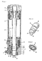
- the piston-cylinder device illustrated in the drawings comprises basically a cylinder 10 with two end walls 11,12, and a piston 13 movably guided in the cylinder 10 and connected to a piston rod 14. Both of the cylinder end walls 11,12 are provided with pressure medium communication ports 16,17 which are connected to a pressure medium control circuit (not shown) for supplying and draining pressure medium to and from the cylinder, respectively, thereby accomplishing movement of the piston 13 in the cylinder 10.
- One of the end walls 12 is formed with an axially extending passageway 18 through which the piston rod 14 extends out of the cylinder 10.
- the piston rod 14 is provided with a connection means 19 for connection to an object to be operated by the device.
- a piston rod 14 locking device 21 comprising a tubular conical clamping element 22 which is axially locked relative to the end wall 12 and arranged to frictionally engage the piston rod 14.
- An activating member 23 in the shape of an annular piston surrounds the clamping element 22 and is axially displaceable relative to the end wall 12 between a clamping element 22 activating position and a clamping element 22 releasing position.
- the activating member 23 is continuously biassed in the direction of the clamping element 22 activating position by a number of springs 24 one of which is illustrated in Figs. 1 and 2.
- the end wall 12 is formed with an internal cylinder portion 26 in which the activating member 23 is sealingly guided.
- the activating member 23 is formed with a tubular neck portion 27 which is sealingly guided in a narrowed part 28 of the passageway 18.
- Pressure medium can reach the cylinder portion 26 via a control port 29 in order to pressurize and displace the activating member 23 in the direction of its release position.
- the control port 29 communicates with the non-illustrated control circuit, and is arranged to be supplied with pressure medium as soon as either one of the two communication ports 16,17 is pressurized. Alternatively, the pressure medium supply to the control port 29 may be controlled separately for obtaining piston rod braking and/or locking functions.
- a manually operable release mechanism including tubular thrust element 32 which is movable in the end wall 12 between a rest position and an activating member 23 releasing position, and a maneuver spindle 33 rotatively supported in the end wall 12 about an axis Y perpendicular to the passageway 18 and the piston rod 14.
- the thrust element 32 is located around a piston rod bushing 34 and has a larger diameter so as to be pivotal in the axial direction of the piston rod 14.
- the thrust element 32 consists of a piece of tubing which has an inclined rear end surface 35, a right angle front surface 36 and a bevelled forward part 37, and at the meeting of the bevelled part 37 and the right angle front surface 36 there are formed two diametrically opposite contact or abutment points 39,40 which are intended to engage the activating member 23.
- the abutment points 39,40 are located at about half the diameter of the thrust element 32. See Fig. 4.
- the thrust element 32 is formed with a lateral opening 41 defining a cam surface for exerting a maneuvering force on the element 32 as the latter is to be pivoted about a support point 42 located on the rear end surface 35, diametrically opposite the opening 41.
- This support point 42 is axially supported against an adjustable set screw 43 mounted in an axially extending threaded bore 44 in the end wall 12. By adjusting the set screw 43, it is possible to compensate for the inevitable spreading of the manufacturing tolerances and set a correct rest position clearance between the thrust element abutment points 39,40 and the activating member 23.
- the maneuver spindle 33 is rotatively supported in a bore 45 defined by a sleeve 38 mounted in the end wall 12. At its inner end, the maneuver spindle 33 is formed with an excentrically disposed cam pin 46 for co-operation with the cam opening 41 in the thrust element 32, and at its outer end the spindle 33 is provided with a grip means 48 for engagement of a tool or other implement for accomplishing a manual rotation of the spindle 33..
- the spindle 33 is also formed with a part-circumferential groove 47 which is intended to co-operate with a stop screw (not shown) to limit the rotational movement of the spindle 33 to a desired angle. See Fig. 5.
- the manuever spindle 32 is formed at its inner end with a diametrically extending slot 49 for engagement with a clock type torsion spring 51. See Fig.6.
- This spring 51 is arranged to exert a rotational bias force on the maneuver spindle 33 in a direction where the thrust element 32 occupies its rest position.
- the spring 51 is formed with a diametrically extending inner end portion 52.
- the spring 51 is formed with a radially directed end portion 53 to be locked relative to the end wall 12.
- the piston 13 and piston rod 14 are locked by the clamping element 22 as the activating member 23 is biassed into engagement therewith by the springs 24. This condition will prevail as long as pressure medium is not supplied via the control port 29 to accomplish a retraction of the activating member 23 against the force of the springs 24.
- the maneuver spindle 33 is operable by a tool or implement to accomplish a movement of the thrust element 32 and the activating member 23.
- the cam pin 46 co-operates with the cam surface defined by the opening 41 to make the thrust element 32 pivot in relation to its support point 42 and the projection 43 in the passageway 18.
- the thrust element 32 engages via its abutment points 39,40 the activating member 23 and urges the latter axially against the load of the springs 24, whereby the engagement between the activating member 23 and the clamping element 22 is interrupted as is the locking engagement between the clamping element 22 and the piston rod 14.
- the cam pin 46 will occupy an end position as the lock device is fully released which means that the engagement point between the cam surfaces on pin 46 and in opening 41 is located on a straight line with the rotation axis of the spindle 33 which is parallel with the load direction of the springs 24. This means that the spring load does not result in a rotational force on the spindle 33 and that the spindle 33 will remain in its locking device release position as long as the spring force prevails.
Landscapes
- Engineering & Computer Science (AREA)
- Physics & Mathematics (AREA)
- Fluid Mechanics (AREA)
- Mechanical Engineering (AREA)
- General Engineering & Computer Science (AREA)
- Actuator (AREA)
- Jigs For Machine Tools (AREA)
Claims (6)
- Durch ein Druckmedium betätigte Kolben-Zylinder-Vorrichtung, die einen Zylinder (10) mit zwei entgegengesetzten Stirnwänden (11, 12), die Verbindungskanäle (16, 17) für das Druckmedium aufweisen, einen Kolben (13), der beweglich in dem Zylinder (10) geführt und mit einer Kolbenstange (14) verbunden ist, die sich durch einen abgedichteten Durchgang (18) aus dem Zylinder (10) heraus erstreckt, eine Arretiervorrichtung für die Kolbenstange (21), die in dem Durchgang (18) angeordnet ist, wenigstens ein Klemmelement (22) aufweist, das relativ zu der ersten Stirnwand (12) axial gesichert ist und so angeordnet ist, daß es reibschlüssig an der Kolbenstange (14) angreift, und ein ständig federnd in Richtung einer Stellung zur Betätigung des Klemmelements (22) vorgespanntes Antriebsglied (23) umfaßt, das durch das Druckmedium zu einer Lösestellung hin gegen diese Vorspannfederkraft verstellbar ist, dadurch gekennzeichnet, daß die Verriegelungsvorrichtung (21) für die Kolbenstange einen manuell betätigbaren Lösemechanismus aufweist, der ein Schubelement (32), das beweglich zwischen einer Ruhestellung und einer Stellung zum Lösen des Antriebsglieds (23) in der ersten Stirnwand (12) gelagert ist, eine Stellspindel (33), die drehbar in der ersten Stirnwand (12) gelagert ist und einen sich außerhalb der Stirnwand (12) erstrekkenden betätigbaren Endbereich (48) aufweist, eine erste Nockenfläche (41), die auf dem Schubelement (32) vorgesehen ist, und eine zweite Nockenfläche (46), die auf der Stellspindel (33) vorgesehen ist, umfaßt, wobei die zweite Nockenfläche (46) an der ersten Nockenfläche (41) angreift, um eine Bewegung des Schubelements (32) zwischen der Ruhestellung und der Stellung zum Lösen des Antriebsglieds (23) zu bewerkstelligen, wenn die Stellspindel (33) gedreht wird.
- Kolben-Zylinder-Vorrichtung nach Anspruch 1, dadurch gekennzeichnet, daß das Schubelement (32) röhrenförmig ist und im wesentlichen koaxial zu der Kolbenstange (14) angeordnet ist, wobei das Schubelement (32) in axialer Richtung des Durchgangs (18) um eine auf dem äußeren Umfang des Schubelements (32) gelegene Lagerstelle (42) schwenkbar ist, die erste Nockenfläche (41) dieser Nokkenfläche (42) diametral gegenüberliegt, und ein Drehen der Stellspindel (33) bewirkt, daß das Schubelement (32) um die Lagerstelle (42) zwischen der Ruhestellung und der Stellung zum Lösen des Antriebsglieds (23) verschwenkt.
- Kolben-Zylinder-Vorrichtung nach Anspruch 2, dadurch gekennzeichnet, daß das Schubelement (32) zwei einander diametral entgegengesetzte und axial ausgerichtete Anlagestellen (39, 40) zum Angreifen an dem Antriebsglied (23) aufweist, wobei diese Anlagestellen (39, 40) beide in einem Winkelabstand von etwa 90° sowohl von der Lagerstelle (42) als auch von der ersten Nockenfläche (41) angeordnet sind.
- Kolben-Zylinder-Vorrichtung nach einem der Ansprüche 1 bis 3, dadurch gekennzeichnet, daß die Stellspindel (33) um eine sich senkrecht zu dem Durchgangs (18) erstreckende Achse drehbar ist.
- Kolben-Zylinder-Vorrichtung nach Anspruch 4, dadurch gekennzeichnet, daß in der Stellung des Schubelements (32) zum Lösen des Antriebsglieds (23) die erste und die zweite Kurvenfläche (41, 46) derartig angeordnet sind, daß sie einander an einer Stelle axial auf einer Linie mit der Rotationsachse (Y) der Stellspindel (33) angreifen, wobei die auf das Antriebsglied (23) wirkende Vorspannfederkraft nicht in der Lage ist, eine Drehkraft auf die Stellspindel (33) auszuüben, und eine Torsionsfeder (51) zwischen der Stellspindel (33) und der ersten Stirnwand (12) befestigt ist, so daß sie eine Drehkraft auf die Stellspindel (33) in Richtung auf die Ruhestellung des Schubelements (32) ausübt.
- Kolben-Zylinder-Vorrichtung nach Anspruch 5, dadurch gekennzeichnet, daß die Torsionsfeder (51) aus einer Spiralfeder besteht.
Applications Claiming Priority (3)
| Application Number | Priority Date | Filing Date | Title |
|---|---|---|---|
| SE9901108A SE521461C2 (sv) | 1999-03-26 | 1999-03-26 | Kolv- cylinderanordning med kolvstångslåsning |
| SE9901108 | 1999-03-26 | ||
| PCT/SE2000/000579 WO2000058632A1 (en) | 1999-03-26 | 2000-03-24 | Piston-cylinder device with piston rod locking means |
Publications (2)
| Publication Number | Publication Date |
|---|---|
| EP1165967A1 EP1165967A1 (de) | 2002-01-02 |
| EP1165967B1 true EP1165967B1 (de) | 2004-08-11 |
Family
ID=20415015
Family Applications (1)
| Application Number | Title | Priority Date | Filing Date |
|---|---|---|---|
| EP00921250A Expired - Lifetime EP1165967B1 (de) | 1999-03-26 | 2000-03-24 | Kolben- zylinder- vorrichtung mit mittel zur verriegelung der kolbenstange |
Country Status (6)
| Country | Link |
|---|---|
| US (1) | US6612221B1 (de) |
| EP (1) | EP1165967B1 (de) |
| JP (1) | JP2002540365A (de) |
| DE (1) | DE60012901T2 (de) |
| SE (1) | SE521461C2 (de) |
| WO (1) | WO2000058632A1 (de) |
Cited By (1)
| Publication number | Priority date | Publication date | Assignee | Title |
|---|---|---|---|---|
| RU2458817C2 (ru) * | 2010-10-07 | 2012-08-20 | Российская Федерация, от имени которой выступает Министерство промышленности и торговли Российской Федерации (Минпромторг России) | Гидроцилиндр с механическим затвором в крайних положениях поршня |
Families Citing this family (8)
| Publication number | Priority date | Publication date | Assignee | Title |
|---|---|---|---|---|
| JP3817197B2 (ja) * | 2002-05-17 | 2006-08-30 | Smc株式会社 | ロック付エアクッションシリンダ装置 |
| US7131518B2 (en) * | 2003-11-14 | 2006-11-07 | Nexen Group, Inc. | Motion control apparatus with backlash reduction |
| PL2570679T3 (pl) | 2009-04-09 | 2014-02-28 | Neumeister Hydraulik Gmbh | Cylinder ryglujący i sposób ryglowania i odryglowywania cylindra ryglującego |
| CN102996574A (zh) * | 2012-12-28 | 2013-03-27 | 内蒙古北方重工业集团有限公司 | 一种液压油缸机械锁 |
| KR101374859B1 (ko) * | 2013-10-28 | 2014-03-17 | 한연수 | 유압 실린더 |
| US20190232464A1 (en) * | 2018-01-29 | 2019-08-01 | Delaware Capital Formation, Inc. | Lock Rod For Pneumatic Swing Clamp |
| CN108518382A (zh) * | 2018-06-19 | 2018-09-11 | 天津隆迪伟业液压设备有限公司 | 一种液压油缸及组装方法 |
| DE102019103917A1 (de) * | 2019-02-15 | 2020-08-20 | Schunk Gmbh & Co. Kg Spann- Und Greiftechnik | Greif- oder Spannvorrichtung mit einer Brems und/oder Festsetzeinheit |
Family Cites Families (9)
| Publication number | Priority date | Publication date | Assignee | Title |
|---|---|---|---|---|
| US3203513A (en) | 1961-05-29 | 1965-08-31 | Valentine E Macy Jr | Braking means for a hydraulic drive cylinder |
| US3918346A (en) * | 1974-07-11 | 1975-11-11 | Us Army | Frictional lock for retaining a rotatable piston against axial displacement |
| US4214795A (en) * | 1977-11-25 | 1980-07-29 | Shoketsu Kinzoku Kogyo Kabushiki Kaisha | Piston braking device for hydraulic or pneumatic cylinders |
| SE441468B (sv) * | 1982-08-20 | 1985-10-07 | Atlas Copco Ab | Losbar lasningsanordning for en tryckmediemanovrerad kolvcylinder |
| JP3380055B2 (ja) * | 1994-08-01 | 2003-02-24 | エスエムシー株式会社 | 流体圧シリンダのロック装置 |
| US6343538B1 (en) * | 1995-08-03 | 2002-02-05 | Frank Raymond Skinner | Multiposition self-locking cylinder |
| CH689114A5 (de) * | 1996-08-23 | 1998-10-15 | Pwb Ag | Feststellvorrichtung einer Linearbewegungseinheit. |
| US5761984A (en) | 1997-03-07 | 1998-06-09 | Advanced Machine & Engineering Co. | Braking device for a fluid power actuator |
| JP3856934B2 (ja) * | 1998-01-27 | 2006-12-13 | Smc株式会社 | ロック機構付き流体圧シリンダ |
-
1999
- 1999-03-26 SE SE9901108A patent/SE521461C2/sv not_active IP Right Cessation
-
2000
- 2000-03-24 US US09/937,798 patent/US6612221B1/en not_active Expired - Fee Related
- 2000-03-24 EP EP00921250A patent/EP1165967B1/de not_active Expired - Lifetime
- 2000-03-24 JP JP2000608096A patent/JP2002540365A/ja active Pending
- 2000-03-24 WO PCT/SE2000/000579 patent/WO2000058632A1/en not_active Ceased
- 2000-03-24 DE DE60012901T patent/DE60012901T2/de not_active Expired - Fee Related
Cited By (1)
| Publication number | Priority date | Publication date | Assignee | Title |
|---|---|---|---|---|
| RU2458817C2 (ru) * | 2010-10-07 | 2012-08-20 | Российская Федерация, от имени которой выступает Министерство промышленности и торговли Российской Федерации (Минпромторг России) | Гидроцилиндр с механическим затвором в крайних положениях поршня |
Also Published As
| Publication number | Publication date |
|---|---|
| DE60012901T2 (de) | 2005-07-14 |
| JP2002540365A (ja) | 2002-11-26 |
| SE9901108L (sv) | 2000-09-27 |
| SE9901108D0 (sv) | 1999-03-26 |
| DE60012901D1 (de) | 2004-09-16 |
| US6612221B1 (en) | 2003-09-02 |
| WO2000058632A1 (en) | 2000-10-05 |
| SE521461C2 (sv) | 2003-11-04 |
| EP1165967A1 (de) | 2002-01-02 |
Similar Documents
| Publication | Publication Date | Title |
|---|---|---|
| EP1165967B1 (de) | Kolben- zylinder- vorrichtung mit mittel zur verriegelung der kolbenstange | |
| EP0161084B1 (de) | Schwenksparren | |
| US5050467A (en) | Wrench socket retainer | |
| GB1567343A (en) | Pneumatically operated percussion boring apparatus | |
| JP2774856B2 (ja) | ディテント機構 | |
| US5916339A (en) | One-way drive mechanism and corresponding ratchet tool | |
| US4111590A (en) | Positive feed drill | |
| AU2011203255B2 (en) | Coupling plug lock | |
| JPH05212687A (ja) | アングルヘッド用係止装置 | |
| US6041818A (en) | Valve assembly | |
| US4726111A (en) | Change head for a tool change apparatus | |
| US4444091A (en) | Safety lock-off throttle device | |
| US3861476A (en) | Control valve for fluid operated tool | |
| US5291086A (en) | Electrical actuator for valve or other device | |
| US7363848B2 (en) | Rotating or pivoting device and connection module for a rotating or pivoting device | |
| US6626073B1 (en) | On car brake lathe aligning apparatus | |
| US5542643A (en) | Pneumatic ball valve operator | |
| US4413805A (en) | Valve detent | |
| US4635856A (en) | Hand-operated sprayers | |
| US4777980A (en) | Adjustment assembly for valve spool and associated centering spring | |
| GB2033742A (en) | Lockable swivel castor | |
| JPH0325480Y2 (de) | ||
| US4919018A (en) | Hydraulic power wrench | |
| JPH0357368Y2 (de) | ||
| JPH06300008A (ja) | 増圧型流体圧シリンダ |
Legal Events
| Date | Code | Title | Description |
|---|---|---|---|
| PUAI | Public reference made under article 153(3) epc to a published international application that has entered the european phase |
Free format text: ORIGINAL CODE: 0009012 |
|
| 17P | Request for examination filed |
Effective date: 20011008 |
|
| AK | Designated contracting states |
Kind code of ref document: A1 Designated state(s): AT BE CH CY DE DK ES FI FR GB GR IE IT LI LU MC NL PT SE |
|
| GRAP | Despatch of communication of intention to grant a patent |
Free format text: ORIGINAL CODE: EPIDOSNIGR1 |
|
| GRAS | Grant fee paid |
Free format text: ORIGINAL CODE: EPIDOSNIGR3 |
|
| GRAA | (expected) grant |
Free format text: ORIGINAL CODE: 0009210 |
|
| AK | Designated contracting states |
Kind code of ref document: B1 Designated state(s): DE FR GB IT |
|
| REG | Reference to a national code |
Ref country code: GB Ref legal event code: FG4D |
|
| REG | Reference to a national code |
Ref country code: IE Ref legal event code: FG4D |
|
| REF | Corresponds to: |
Ref document number: 60012901 Country of ref document: DE Date of ref document: 20040916 Kind code of ref document: P |
|
| PGFP | Annual fee paid to national office [announced via postgrant information from national office to epo] |
Ref country code: FR Payment date: 20050308 Year of fee payment: 6 |
|
| PGFP | Annual fee paid to national office [announced via postgrant information from national office to epo] |
Ref country code: DE Payment date: 20050317 Year of fee payment: 6 |
|
| PGFP | Annual fee paid to national office [announced via postgrant information from national office to epo] |
Ref country code: GB Payment date: 20050323 Year of fee payment: 6 |
|
| PLBE | No opposition filed within time limit |
Free format text: ORIGINAL CODE: 0009261 |
|
| STAA | Information on the status of an ep patent application or granted ep patent |
Free format text: STATUS: NO OPPOSITION FILED WITHIN TIME LIMIT |
|
| ET | Fr: translation filed | ||
| 26N | No opposition filed |
Effective date: 20050512 |
|
| PG25 | Lapsed in a contracting state [announced via postgrant information from national office to epo] |
Ref country code: GB Free format text: LAPSE BECAUSE OF NON-PAYMENT OF DUE FEES Effective date: 20060324 |
|
| PGFP | Annual fee paid to national office [announced via postgrant information from national office to epo] |
Ref country code: IT Payment date: 20060331 Year of fee payment: 7 |
|
| PG25 | Lapsed in a contracting state [announced via postgrant information from national office to epo] |
Ref country code: DE Free format text: LAPSE BECAUSE OF NON-PAYMENT OF DUE FEES Effective date: 20061003 |
|
| GBPC | Gb: european patent ceased through non-payment of renewal fee |
Effective date: 20060324 |
|
| REG | Reference to a national code |
Ref country code: FR Ref legal event code: ST Effective date: 20061130 |
|
| PG25 | Lapsed in a contracting state [announced via postgrant information from national office to epo] |
Ref country code: FR Free format text: LAPSE BECAUSE OF NON-PAYMENT OF DUE FEES Effective date: 20060331 |
|
| PG25 | Lapsed in a contracting state [announced via postgrant information from national office to epo] |
Ref country code: IT Free format text: LAPSE BECAUSE OF NON-PAYMENT OF DUE FEES Effective date: 20070324 |