EP1166143B1 - Systeme und verfahren zur auflösung der vieldeutigkeit von gps pseudo-entfernungen - Google Patents
Systeme und verfahren zur auflösung der vieldeutigkeit von gps pseudo-entfernungen Download PDFInfo
- Publication number
- EP1166143B1 EP1166143B1 EP00913834A EP00913834A EP1166143B1 EP 1166143 B1 EP1166143 B1 EP 1166143B1 EP 00913834 A EP00913834 A EP 00913834A EP 00913834 A EP00913834 A EP 00913834A EP 1166143 B1 EP1166143 B1 EP 1166143B1
- Authority
- EP
- European Patent Office
- Prior art keywords
- mobile terminal
- gps
- satellite
- spot
- trial
- Prior art date
- Legal status (The legal status is an assumption and is not a legal conclusion. Google has not performed a legal analysis and makes no representation as to the accuracy of the status listed.)
- Expired - Lifetime
Links
- 238000000034 method Methods 0.000 title claims abstract description 54
- 238000004891 communication Methods 0.000 claims abstract description 119
- 239000011159 matrix material Substances 0.000 claims description 11
- 238000005259 measurement Methods 0.000 abstract description 28
- 230000005540 biological transmission Effects 0.000 description 19
- 238000013459 approach Methods 0.000 description 14
- 238000004364 calculation method Methods 0.000 description 14
- 238000012546 transfer Methods 0.000 description 14
- 230000006870 function Effects 0.000 description 11
- 230000008569 process Effects 0.000 description 11
- 230000001413 cellular effect Effects 0.000 description 10
- 101150103425 APR1 gene Proteins 0.000 description 7
- 239000000243 solution Substances 0.000 description 7
- 238000001228 spectrum Methods 0.000 description 7
- 239000000969 carrier Substances 0.000 description 6
- 238000012545 processing Methods 0.000 description 5
- 230000002441 reversible effect Effects 0.000 description 5
- 101100163944 Necator americanus apr-2 gene Proteins 0.000 description 3
- 230000008901 benefit Effects 0.000 description 3
- 238000005516 engineering process Methods 0.000 description 3
- 230000035515 penetration Effects 0.000 description 3
- 238000004590 computer program Methods 0.000 description 2
- 238000000354 decomposition reaction Methods 0.000 description 2
- 230000007123 defense Effects 0.000 description 2
- 238000010586 diagram Methods 0.000 description 2
- 239000000284 extract Substances 0.000 description 2
- 238000012986 modification Methods 0.000 description 2
- 230000004048 modification Effects 0.000 description 2
- 238000013488 ordinary least square regression Methods 0.000 description 2
- 230000009467 reduction Effects 0.000 description 2
- 230000001360 synchronised effect Effects 0.000 description 2
- IRLPACMLTUPBCL-KQYNXXCUSA-N 5'-adenylyl sulfate Chemical compound C1=NC=2C(N)=NC=NC=2N1[C@@H]1O[C@H](COP(O)(=O)OS(O)(=O)=O)[C@@H](O)[C@H]1O IRLPACMLTUPBCL-KQYNXXCUSA-N 0.000 description 1
- 238000004458 analytical method Methods 0.000 description 1
- 238000012937 correction Methods 0.000 description 1
- 230000001934 delay Effects 0.000 description 1
- 230000001419 dependent effect Effects 0.000 description 1
- 238000013461 design Methods 0.000 description 1
- 238000001514 detection method Methods 0.000 description 1
- 239000012895 dilution Substances 0.000 description 1
- 238000010790 dilution Methods 0.000 description 1
- 238000009826 distribution Methods 0.000 description 1
- 230000000694 effects Effects 0.000 description 1
- 238000011156 evaluation Methods 0.000 description 1
- PCHJSUWPFVWCPO-UHFFFAOYSA-N gold Chemical compound [Au] PCHJSUWPFVWCPO-UHFFFAOYSA-N 0.000 description 1
- 239000010931 gold Substances 0.000 description 1
- 229910052737 gold Inorganic materials 0.000 description 1
- 238000002372 labelling Methods 0.000 description 1
- 238000013507 mapping Methods 0.000 description 1
- 238000010295 mobile communication Methods 0.000 description 1
- 238000011084 recovery Methods 0.000 description 1
- 230000004044 response Effects 0.000 description 1
- 230000000717 retained effect Effects 0.000 description 1
- 230000035945 sensitivity Effects 0.000 description 1
- 230000008054 signal transmission Effects 0.000 description 1
- 238000012360 testing method Methods 0.000 description 1
- 238000012876 topography Methods 0.000 description 1
- 238000009827 uniform distribution Methods 0.000 description 1
Images





Classifications
-
- G—PHYSICS
- G01—MEASURING; TESTING
- G01S—RADIO DIRECTION-FINDING; RADIO NAVIGATION; DETERMINING DISTANCE OR VELOCITY BY USE OF RADIO WAVES; LOCATING OR PRESENCE-DETECTING BY USE OF THE REFLECTION OR RERADIATION OF RADIO WAVES; ANALOGOUS ARRANGEMENTS USING OTHER WAVES
- G01S19/00—Satellite radio beacon positioning systems; Determining position, velocity or attitude using signals transmitted by such systems
- G01S19/01—Satellite radio beacon positioning systems transmitting time-stamped messages, e.g. GPS [Global Positioning System], GLONASS [Global Orbiting Navigation Satellite System] or GALILEO
- G01S19/13—Receivers
- G01S19/24—Acquisition or tracking or demodulation of signals transmitted by the system
- G01S19/25—Acquisition or tracking or demodulation of signals transmitted by the system involving aiding data received from a cooperating element, e.g. assisted GPS
- G01S19/252—Employing an initial estimate of location in generating assistance data
-
- G—PHYSICS
- G01—MEASURING; TESTING
- G01S—RADIO DIRECTION-FINDING; RADIO NAVIGATION; DETERMINING DISTANCE OR VELOCITY BY USE OF RADIO WAVES; LOCATING OR PRESENCE-DETECTING BY USE OF THE REFLECTION OR RERADIATION OF RADIO WAVES; ANALOGOUS ARRANGEMENTS USING OTHER WAVES
- G01S19/00—Satellite radio beacon positioning systems; Determining position, velocity or attitude using signals transmitted by such systems
- G01S19/01—Satellite radio beacon positioning systems transmitting time-stamped messages, e.g. GPS [Global Positioning System], GLONASS [Global Orbiting Navigation Satellite System] or GALILEO
- G01S19/13—Receivers
- G01S19/24—Acquisition or tracking or demodulation of signals transmitted by the system
-
- G—PHYSICS
- G01—MEASURING; TESTING
- G01S—RADIO DIRECTION-FINDING; RADIO NAVIGATION; DETERMINING DISTANCE OR VELOCITY BY USE OF RADIO WAVES; LOCATING OR PRESENCE-DETECTING BY USE OF THE REFLECTION OR RERADIATION OF RADIO WAVES; ANALOGOUS ARRANGEMENTS USING OTHER WAVES
- G01S19/00—Satellite radio beacon positioning systems; Determining position, velocity or attitude using signals transmitted by such systems
- G01S19/38—Determining a navigation solution using signals transmitted by a satellite radio beacon positioning system
- G01S19/39—Determining a navigation solution using signals transmitted by a satellite radio beacon positioning system the satellite radio beacon positioning system transmitting time-stamped messages, e.g. GPS [Global Positioning System], GLONASS [Global Orbiting Navigation Satellite System] or GALILEO
- G01S19/42—Determining position
-
- G—PHYSICS
- G01—MEASURING; TESTING
- G01S—RADIO DIRECTION-FINDING; RADIO NAVIGATION; DETERMINING DISTANCE OR VELOCITY BY USE OF RADIO WAVES; LOCATING OR PRESENCE-DETECTING BY USE OF THE REFLECTION OR RERADIATION OF RADIO WAVES; ANALOGOUS ARRANGEMENTS USING OTHER WAVES
- G01S19/00—Satellite radio beacon positioning systems; Determining position, velocity or attitude using signals transmitted by such systems
- G01S19/38—Determining a navigation solution using signals transmitted by a satellite radio beacon positioning system
- G01S19/39—Determining a navigation solution using signals transmitted by a satellite radio beacon positioning system the satellite radio beacon positioning system transmitting time-stamped messages, e.g. GPS [Global Positioning System], GLONASS [Global Orbiting Navigation Satellite System] or GALILEO
- G01S19/42—Determining position
- G01S19/45—Determining position by combining measurements of signals from the satellite radio beacon positioning system with a supplementary measurement
- G01S19/46—Determining position by combining measurements of signals from the satellite radio beacon positioning system with a supplementary measurement the supplementary measurement being of a radio-wave signal type
-
- G—PHYSICS
- G01—MEASURING; TESTING
- G01S—RADIO DIRECTION-FINDING; RADIO NAVIGATION; DETERMINING DISTANCE OR VELOCITY BY USE OF RADIO WAVES; LOCATING OR PRESENCE-DETECTING BY USE OF THE REFLECTION OR RERADIATION OF RADIO WAVES; ANALOGOUS ARRANGEMENTS USING OTHER WAVES
- G01S19/00—Satellite radio beacon positioning systems; Determining position, velocity or attitude using signals transmitted by such systems
- G01S19/01—Satellite radio beacon positioning systems transmitting time-stamped messages, e.g. GPS [Global Positioning System], GLONASS [Global Orbiting Navigation Satellite System] or GALILEO
- G01S19/03—Cooperating elements; Interaction or communication between different cooperating elements or between cooperating elements and receivers
- G01S19/09—Cooperating elements; Interaction or communication between different cooperating elements or between cooperating elements and receivers providing processing capability normally carried out by the receiver
Definitions
- the present invention generally relates to wireless communications systems and methods, and more particularly to wireless mobile terminals, systems and methods.
- Public wireless radiotelephone systems are commonly employed to provide voice and data communications to subscribers.
- analog cellular radiotelephone systems such as designated AMPS, ETACS, NMT-450, and NMT-900
- Digital cellular radiotelephone systems such as those conforming to the North American standard IS-54 and the European standard GSM have been in service since the early 1990's.
- PCS Personal Communications Services
- advanced digital cellular systems conforming to standards such as IS-136 and IS-95
- DECT Digital Enhanced Cordless Telephone
- CDPD Cellular Digital Packet Data
- FIG. 1 illustrates a conventional terrestrial wireless communication system 20 that may implement any one of the aforementioned wireless communications standards.
- the wireless system may include one or more wireless mobile terminals 22 that communicate with a plurality of cells 24 served by base stations 26 and a Mobile Telephone Switching Office (MTSO) 28 .
- MTSO Mobile Telephone Switching Office
- FIG. 1 a typical cellular radiotelephone network may comprise hundreds of cells, may include more than one MTSO 28 and may serve thousands of wireless mobile terminals 22 .
- the cells 24 generally serve as nodes in the communication system 20 , from which links are established between wireless mobile terminals 22 and an MTSO 28 , by way of the base stations 26 servicing the cells 24 .
- Each cell 24 will have allocated to it one or more dedicated control channels and one or more traffic channels.
- the control channel is a dedicated channel used for transmitting cell identification and paging information.
- the traffic channels carry the voice and data information.
- a duplex radio communication link 30 may be effected between two wireless mobile terminals 22 or between a wireless mobile terminal 22 and a landline telephone user 32 via a Public Switched Telephone Network (PSTN) 34 .
- PSTN Public Switched Telephone Network
- the base station 26 generally handles the radio communications between the base station 26 and the wireless mobile terminal 22 . In this capacity, the base station 26 may function as a relay station for data and voice signals.
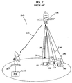
- FIG. 2 illustrates a conventional celestial (satellite) communication system 120 .
- the satellite wireless communication system 120 may be employed to perform similar functions to those performed by the conventional terrestrial wireless communication system 20 of FIG. 1 .
- the celestial wireless communication system 120 typically includes one or more satellites 126 that serve as relays or transponders between one or more earth stations 127 and satellite wireless mobile terminals 122 .
- the satellite 126 communicates with the satellite wireless mobile terminals 122 and earth stations 127 via duplex communication links 130 .
- Each earth station 127 may in turn be connected to a PSTN 132 , allowing communications between the wireless mobile terminals 122 , and communications between the wireless mobile terminals 122 and conventional terrestrial wireless mobile terminals 22 ( FIG. 1 ) or landline telephones 32 ( FIG. 1 ).
- the satellite wireless communication system 120 may utilize a single antenna beam covering the entire area served by the system, or as shown in FIG. 2 , the satellite wireless communication system 120 may be designed such that it produces multiple, minimally-overlapping beams 134 , each serving a distinct geographical coverage area 136 within the system's service region.
- a satellite 126 and coverage area 136 may serve a function similar to that of a base station 26 and cell 24 , respectively, of the terrestrial wireless communication system 20 .
- the satellite wireless communication system 120 may be employed to perform similar functions to those performed by conventional terrestrial wireless communication systems.
- a satellite radiotelephone communication system 120 may have particular application in areas where the population is sparsely distributed over a large geographic area or where rugged topography tends to make conventional landline telephone or terrestrial wireless infrastructure technically or economically impractical.
- GPS Global Positioning System
- GPS refers to a space-based trilateration system using satellites 302 and computers 308 to measure positions anywhere on the earth.
- GPS was originally introduced and often is used to refer to a system developed by the United States Department of Defense as a navigational system. However, for purposes of this application, the term GPS refers more generally to both the Department of Defense system and other space-based systems such as GLONASS. Compared to other Iand-based systems, GPS may be unlimited in its coverage, may provide continuous 24-hour coverage regardless of weather conditions, and may be highly accurate. While the GPS technology that provides the greatest level of accuracy has been retained by the government for military use, a less accurate Standard Positioning Service (SPS) has been made available for civilian use.
- SPS Standard Positioning Service
- a constellation of 24 GPS satellites 302 orbiting the earth continually emit a GPS radio frequency signal 304 at a predetermined chip frequency.
- a GPS receiver 306 e.g., a hand-held radio receiver with a GPS processor, receives the radio signals from visible satellites and measures the time that the radio signals take to travel from the GPS satellites to the GPS receiver antenna. By multiplying the travel time by the speed of light, the GPS receiver can calculate a range for each satellite in view. From additional information provided in the radio signal from the satellites, including the satellite's orbit and velocity and correlation to its onboard clock, the GPS processor can calculate the position of the GPS receiver through a process of trilateration.
- the GPS signal 304 generally consists of a spread-spectrum signal that has a code-length of 1023 chips (bits), and it is transmitted at a chip-rate of 1.023 MHz. This results in a code period of one millisecond.
- Overlaid on top of the spread-spectrum sequence is a 50 bits/second (bps) navigation message which, typically, contains ephemeris/almanac data as well as timing information which is used to timestamp the transmit time of the signal from the GPS satellite 302 .
- the timestamp which is generally transmitted in each sub-frame of the 1500 bit navigation message, each sub-frame consisting of 300 bits, is used to calculate the integer number of C/A (coarse acquisition Gold code) code lengths between the GPS satellite 302 and current position of GPS receiver 306 .
- the decoding of the timestamp could take up to twelve seconds. On average, it takes 9 seconds to decode a sub-frame and extract the timestamp in order to resolve the one millisecond ambiguity (from the code period).
- the code-phase measurements for the GPS SPS signal have a one-millisecond ambiguity due to the inherent nature of the received GPS spread-spectrum signal.
- the spread-spectrum signal is generated by repeatedly transmitting a unique Gold-code for each of the GPS satellites.
- Each of the Gold-codes is 1023 chips (bits) in length, and they are transmitted at a 1.023 chips/sec rate.
- the chip length divided by the chip rate gives the Gold-code period of one millisecond.
- Measurement of the code phase determines the fractional number of Gold-code lengths between the GPS satellite and the GPS receiver. The problem remains of determining the integer number of code periods between the GPS satellite and the GPS receiver.
- Each sub-frame in the navigation message contains a time-stamp that represents the time of transmission of the sub-frame.
- the GPS receiver extracts the time-stamp from the naviagion message and subtracts it from the current time to estimate the integer number of code-periods from the GPS satellite and the GPS receiver. If the receiver estimate of the GPS time is in error the time-bias will be common to all of the pseudo-range measurements, and it may be removed when the point fix solution is calculated.
- the receiver Before the data can be demodulated, the receiver generally needs to acquire the GPS signal 304 and achieve code and carrier lock. As well as increasing the time to obtain a GPS position fix, demodulating the GPS navigation data complicates the design of the GPS receiver 306 .
- the wireless communications system provides transmissions and reception in a plurality of spotbeams or cells comprising a large area.
- the wireless network broadcasts to user terminals within each spotbeam or cell, the GPS ID of all satellites that are visible within the zone along with Doppler and signal strength estimates for the visible GPS satellites.
- the user uses the broadcast GPS aiding data to quickly acquire the GPS C/A signals for all visible GPS satellites.
- the user terminal then returns the GPS C/A code measurements to the wireless network which processes the measurements in conjunction with separate GPS data which it also receives to determine the users location.
- GPS receiver and radio communication receiver which receives information, such as GPS satellite Doppler information from a terrestrial base station, for use in determining position as described in United States Patent No. 5,663, 734 to Krasner entitled “GPS Receiver and Method for Processing GAS Signals”. It is also known to provide a GPS receiver with GPS satellite position information transmitted over a communication channel supported by terrestrial cellular telephone or other radio packet data services as described in United States Patent No. 5,365,450 to Schuchman entitled " Hybrid GPS / Data line Unit for Rapid, Precise, and Robust Position Determination ".
- the present invention by providing methods and systems for determining a position of a mobile terminal that includes a satellite radiotelephone and a global positioning system (GPS) receiver based on knowledge of the position of the communication satellite spot-beam in which the mobile terminal is located.
- GPS global positioning system
- the present invention can resolve the one-millisecond ambiguity, that typically arises from the code repeat length where relative code phase may be determined but absolute code phase (i.e. one millisecond increments) could be off by one or more code periods.
- the spot-beam identifier is obtained from the satellite communication system and used to determine the geographic location of the spot-beam.
- Trial positions i.e., candidate mobile terminal positions
- Pseudo-range measurements are generated for each trial position and used to generate position fixes.
- the best position fix for example a fix selection based on a consistency check, is then selected as the mobile terminal's position.
- the number of trial positions is reduced by selecting an arc of positions within the spot-beam as trial positions based on timing delay information from the satellite communication system.
- a method for determining a position of a mobile terminal.
- An identification of a spot-beam in which the mobile terminal is located is obtained from a satellite radiotelephone system communication and a plurality of trial positions within the spot-beam are generated.
- Candidate position fixes for the mobile terminal are generated for at least two of the plurality of trial positions based on GPS signals received by the mobile terminal from a plurality of global positioning system (GPS) satellites.
- GPS global positioning system
- the candidate position fixes may be determined by calculating a plurality of initial pseudo-range estimates corresponding to the plurality of GPS satellites for one of the plurality of trial positions based on the GPS signals received by the mobile terminal, the GPS signals having a code length, including determining fractional code periods from the received GPS signals.
- the initial pseudo-range estimates may then be adjusted to produce a plurality of candidate pseudo-range estimates for the mobile terminal for the one of the plurality of trial positions and the candidate position fix for the mobile terminal may then be generated for the one of the plurality of trial positions based on the plurality of candidate pseudo-range estimates.
- the calculating, adjusting and generating operations may be repeated for each of the plurality of trial positions.
- adjusting operations include truncating each of the initial pseudo-range estimates to produce a corresponding plurality of integer code length distances for the one of the plurality of trial positions and adding distances corresponding to the fractional code periods derived from the received GPS signals to the plurality of integer code length distances to provide a corresponding plurality of candidate pseudo-range estimates for the mobile terminal.
- adjusting operations may include modifying the plurality of initial pseudo-range estimates to account for relative differences between the fractional code periods derived from the received GPS signals to provide a corresponding plurality of candidate pseudo-range estimates for the mobile terminal. Range and position fix calculations may be carried out by the mobile terminal or at a remote location.
- the calculating, adjusting and generating operations may be repeated for each of the plurality of trial positions to provide candidate position fixes for the mobile terminal for each of the plurality of trial positions.
- the plurality of GPS satellites are first selected from visible GPS satellites based on the elevation of the visible GPS satellites relative to one of the plurality of trial positions.
- the position fixes are least squares position fixes and at least four GPS satellites are used in determining position fixes.
- One of the candidate position fixes is then selected as the position of the mobile terminal based on a self-consistency check.
- the selection may be made using an overdetermined set of equations.
- the selection is made by Q-R decomposing a direction cosine matrix determined from the candidate position fixes and multiplying non-constrained dimensions of a transpose of a Q matrix by delta pseudo-range values from the candidate position fixes.
- each of the trial positions is located no more than approximately 150 kilometers of another of the plurality of trial positions.
- the plurality of trial positions are generated on a grid covering the spot-beam.
- the spot-beam identifier is received from the satellite radiotelephone system communication and a geographic location of the spot-beam is calculated based on the received spot-beam identifier.
- the location calculation may be based on satellite ephemeris data obtained from the satellite radiotelephone system communication and antenna direction coordinates or, alternatively, on boundary points for the spot-beam stored in the mobile terminal.
- satellite communication timing information is also obtained from the satellite radiotelephone system communication and the plurality of trial positions is generated based on the obtained timing information.
- the timing information may be timing delay information in which case the plurality of trial positions are selected along an arc of positions substantially equidistant from a satellite transmitting the satellite radiotelephone system communication based on the timing delay information.
- the plurality of trial positions may be selected along at least one arc of positions substantially equidistant from a satellite transmitting the satellite radiotelephone system communication based on the timing delay information wherein each of the trial positions is located no more than approximately 150 kilometers of another of the plurality of trial positions.
- the satellite communication timing information is requested from a satellite radiotelephone system satellite on a high margin random access channel.
- the satellite communication timing information is received from the satellite radiotelephone system satellite on a high margin paging channel.
- the timing information is timing delay information
- a request is transmitted which includes a timing update request having a request number identifier and a timing update is then received having an associated identifier corresponding to the request number identifier.
- a GPS signal is received at the mobile terminal from each of the plurality of GPS satellites.
- a code phase is determined for each of the plurality of GPS satellites from the received GPS signals at the mobile terminal.
- the determined code phases are then provided to a remote GPS station from the mobile terminal which determines the candidate position fixes and selects one as the position of the mobile terminal.
- the present invention has generally been described above with reference to method aspects of the present invention, it is to be understood that the present invention also provides for mobile terminals and systems for determining a position of a mobile terminal.
- FIG. 1 illustrates a conventional terrestrial (cellular) wireless communication system.
- FIG. 2 illustrates a conventional celestial (satellite) wireless communication system.
- FIG. 3 illustrates a conventional global positioning system (GPS).
- GPS global positioning system
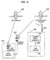
- FIG. 4 is a block diagram of a mobile terminal interfaced to GPS and wireless communication systems according to an embodiment of the present invention.
- FIG. 5 is a flowchart illustrating position computation operations according to an embodiment of the present invention.
- FIG. 6 illustrates selection of trial positions in a spot-beam according to two embodiments of the present invention.
- FIG. 7 illustrates an exemplary RACH access period for an ACeS satellite communication system.
- FIG. 8 illustrates an exemplary multiframe structure for an ACeS satellite communication system.
- FIG. 9 illustrates an HRACH access period according to an embodiment of the present invention.
- FIG. 10 is a flowchart illustrating timing delay acquisition operations according to an embodiment of the present invention.
- FIG. 4 a block diagram of a mobile terminal according to the present invention is illustrated. It will be understood that mobile terminal 400 may be used in place of a satellite wireless mobile terminal 122 of FIG. 2 and a GPS receiver 306 of FIG. 3 , at locations that are served by both a satellite communication system 120 ( FIG. 2 ) and a GPS system 300 ( FIG. 3 ). It is also to be understood that, while the-present invention will be described with reference to satellite communication systems, it can be beneficially utilized to address time ambiguity in any number of different systems with an ability to identify a geographic region in which a mobile terminal is located.
- mobile terminal 400 includes a satellite radiotelephone 404 that is configured to provide for communications through communication satellite 126 of a satellite communication network 120 such as that illustrated in FIG. 2 . More particularly, satellite radiotelephone 404 is configured to provide for receipt of a spot-beam identifier and timing delay information from communication satellite 126 .
- a GPS receiver 406 within mobile terminal 400 is configured to receive GPS signal transmissions 304 from GPS satellite 302 . While only a single GPS satellite 302 is. illustrated in FIG. 4 . it is to be understood that a plurality of GPS satellites within the visible ranage of mobile terminal 400 provide signals which may be received by GPS receiver 406 and used in determining a position of mobile terminal 400 .
- a single antenna 402 is shown in FIG. 4 , separate antennas may be provided for receiving signals from GPS satellite 302 and communication satellite 126 , respectively.
- GPS receiver 406 further receives spot-beam identification information and, optionally, timing delay information from satellite radiotelephone 404 for use in computing the position of mobile terminal 400 .
- GPS receiver 406 further may receive GPS satellite ephemeris and timing information (which may be obtained from remote GPS station 412 coupled to satellite communication ground station 410 ) from satellite radiotelephone 404 for use in computing the position of mobile terminal 400 .
- the GPS receiver 406 receives GPS signals 304 from GPS satellite 302 and determines code phase (shift), which information is provided through satellite radiotelephone 404 to remote GPS station 412 for position fix calculation. In this embodiment, GPS receiver 406 need not obtain ephemeris information from satellite radiotelephone 404 .
- a set of pseudo-ranges associated with a selected plurality of GPS satellites 302 can still be estimated if the position of GPS receiver 306 is known to within 150 kilometers.
- Each of these initial pseudo-range estimates is then adjusted to account for the relative differences between the fractional code period measurements made by the GPS receiver 306 .
- An accurate position fix can be generated from the resulting set of adjusted pseudo-range estimates using known techniques.
- spot-beams project elliptical patterns on the earth's surface which have major axis lengths may easily exceed 1000 kilometers. As a result, knowing the location of the spot-beam alone is generally not sufficient for developing a usable set of pseudo-range estimates without decoding the navigation message.
- the computed position information may be displayed, or may be broadcast, for example, through satellite communication system 120 , or used for other purposes as is conventionally known. It will also be understood that mobile terminal 400 may further include conventional user interface elements, such as keypads and displays and other electronic components known to those having skill in the art. Therefore, these aspects of satellite radiotelephone 404 will not be further described herein except as they relate to the present invention.
- FIG. 4 may be provided by hardware, software, or a combination of the above.
- various components of mobile terminal 400 have been illustrated as discrete components, they may also, in practice, be implemented in an integrated fashion using a microcontroller including input and output ports and running software code, by custom or hybrid chips, by discrete components or by a combination of the above.
- all or some of the components represented by GPS receiver 406 may be implemented using code executing on a microprocessor or a digital signal processor, or by an application specific integrated circuit (ASIC).
- ASIC application specific integrated circuit
- an identification of a spot-beam in which the mobile terminal is located is obtained from the satellite communication system 120 based on a communication on a wireless link from communications satellite 126 .
- the spot-beam identifier can be obtained by reading the High Penetration Broadcast Control Channel (HBCCH).
- HBCCH High Penetration Broadcast Control Channel
- the location of the spot-beam can then be calculated based on knowledge of the satellite system coverage or, as an alternative, spot-beam boundary points stored in memory of mobile terminal 400 may be used in determining spot-beam location.
- this obtained knowledge of the location of the current spot-beam in which mobile terminal 400 is located will be used to resolve the one millisecond GPS pseudo-range ambiguity to arrive at the position of mobile terminal 400 .
- this approach assumes that mobile terminal 400 is able to decode the HBCCH so that it can determine the spot-beam identifier.
- the HBCCH is specifically provided so as to allow receipt of communications even by a disadvantaged mobile terminal.
- the spot-beam location may be calculated using a combination of satellite ephemeris data and antenna direction coordinates.
- boundary points defining the location of each spot-beam could be stored in memory of mobile terminal 400 and indexed based upon spot-beam identifier.
- mobile terminal 400 measures the code phase (shift) of signals 304 received by GPS receiver 406 from each of a plurality of visible GPS satellites 302 .
- the code phase (shift) readings will be used in calculating pseudo-ranges and position fixes as described further herein.
- the code phase readings from a set of GPS satellites 302 are all that is required from the GPS signals 304 as the ephemeris/almanac and timing information may be obtained through ahternative sources.
- the remaining GPS calculation information may be received by mobile terminal 400 , for example, from satellite communication system 120 .
- mobile terminal 400 may simply provide a remote GPS station 412 , which does obtain timing and ephemeris data from the GPS satellites 302 , the code phase measurements and spot-beam identifier (or other means to calculate the spot-beam location) so that the remaining operations to be described with reference to FIG. 5 need not be performed by mobile terminal 400 .
- the spot-beam information may be provided directly by mobile terminal 400 along with the code phase measurements or may be provided to the remote GPS station 412 by satellite communication system 120 which is also aware of what spot-beam mobile terminal 400 is located within.
- mobile terminal 400 determines the location of the current spot-beam in which it is located, it generates a list of positions within the current spot-beam geographic coverage area to use as a set of trial positions for computing position fixes (block 424 ).
- the plurality of trial positions are selected from locations on a grid covering the spot-beam.
- the trial positions are preferably located on a grid such that each trial position is located no more than approximately 150 kilometers from another of the plurality of trial positions.
- GPS determinations are generally based on measurements taken from a plurality of GPS satellites 302 , preferably a set of at least 5 such GPS satellites. These measurements from 5 GPS satellites typically provide for a location determination including latitude, longitude, altitude and time reference. Therefore, at block 422 , a plurality of GPS satellites 302 are selected from the visible GPS satellites based on the elevation of the visible GPS satellites relative to one of the plurality of trial positions. Satellites with high elevations have lower probabilities of having an ambiguous pseudo-range and, therefore, are preferable for use according to the methods of the present invention.
- Operations for estimating pseudo-ranges may vary based on the accuracy of the GPS time information available as will now be described (along with their relation to operations at blocks 430 and 432 ) with reference to embodiments of operations for estimating pseudo-ranges suitable for use with the present invention under various conditions. However, it is to be understood that other techniques for estimating pseudo-ranges known to those of skill in the art may also be beneficially used according to the present invention.
- “precisely known” refers to a user receiver initial GPS system time estimate accurate to within ⁇ 5 ⁇ s (or better). Under these conditions, the time estimate is expected to be accurate to within ⁇ 0.5% of the 1ms GPS code epoch.
- the operations described herein further are preferably carried out by a user (GPS) receiver able to align its 1 ms timing strobe with this time estimate. For a given trial position, a user location is assumed for each trial position to be within 150 km of the trial position.
- the user receiver preferably measures a "snapshot" of code phases from at least 5 GPS satellites.
- the task of calculating an initial set of five or more pseudo-range estimates for a particular trial position is relatively straightforward.
- the receiver computes the position of the target satellite at the precise time of interest and subtracts from it the known position of the trial position concerned.
- the magnitude of the resulting vector quantity serves as the initial pseudo-range estimate.
- each of these initial pseudo-range estimates is adjusted to enable its use in the computation of a GPS fix.
- the precise knowledge of absolute GPS time allows these initial pseudo-range estimates to be adjusted independently of one another.
- the adjustment step for an individual pseudo-range estimate consists of two parts.
- the pseudo-range estimate (in milliseconds) is truncated to an integer number of milliseconds. Truncation operations may be based upon the difference between the fractional portion of the initial pseudo-range estimate and the corresponding code phase measurement produced by the user receiver. This approach is based on the fact that a code phase measurement generally cannot deviate from the fractional portion of the estimate by more than 1 ⁇ 2 ms if the position uncertainty is constrained to within approximately 150km.
- the second step is to add the code phase measurement to its corresponding truncated initial pseudo-range estimate.
- the receiver may proceed to generate a GPS position fix according to known techniques such as least squares.
- the embodiment described herein is preferably used when the user receiver initial GPS system time estimate accurate to within ⁇ 1ms (or worse). Under these conditions, the GPS time uncertainty is expected to span at least one 1ms GPS code period (epoch) and the user receiver 1ms timing strobe is not expected to have a meaningful relationship to absolute GPS time. For a given trial position, a user location is assumed for each trial position to be within 75 km of the trial position. Furthermore, the user receiver preferably measures a "snapshot" of code phases from at least 5 GPS satellites.
- the adjustment process can commence by arbitrarily labeling the five (or more) code phase measurements.
- this first code phase measurement to be cp1 and the others to be cp2, cp3, cp4 and cp5.
- a particular chip of the GPS signal from satellite_1 is expected to be received somewhere between 11.3ms to 12.3ms prior to receiving it from satellite_2.
- the delay observed by the user equals 11ms plus some fractional offset or 12ms plus some fractional offset.
- the code phase measurements cp1 and cp2 indicate that the fractional difference between the two received signals is 0.4955 ms
- two possible values for the delay between satellite_1 and satellite_2 signals are considered, namely 11.4955ms and 12.4955ms. Because the actual delay is expected to exist within the interval (11.3ms, 12.3ms), it may be assumed that the user receives the GPS signal from satellite_1 11.4955ms sooner that transmitted by satellite_2. Note that it would be expected to be impossible to interpret this user-observed delay to be 12.4995ms due to the trial position spacing constraint.
- a meaningful value may be assigned to the adjusted pseudo-range estimate for satellite_2.
- apr1 72.4000 ms
- apr2 (apr1 + 11.4955)
- ms apr2 83.8955 ms
- cp3, cp4 and cp5 are then performed for cp3, cp4 and cp5 to obtain adjusted pseudo-range estimates for the third, fourth and fifth satellites respectively.
- the measurement (cp1) and the adjusted pseudo-range estimate (apr1) from satellite_1 may be used as a central reference.
- the resulting set of adjusted estimates is expected to reflect the relative code phase relationships demonstrated by the observed code phase measurements.
- the adjustment method described above may not be optimal in that it treats all pseudo-range estimates identically and processes them in an arbitrary order. As a result, the 75 km radial constraint is applied to handle the worst-case where measurements from two low-elevation antipodal satellites must be related.
- the radial constraint can be relaxed back toward the limit of 150 km discussed for the precise timing scenario above.
- a single reference be employed.
- the adjustment of pseudo-range estimates can be ordered in such a way that satellites are sequentially related to the satellite which most closely shares its geometrical relation to the user. Consequently, various schemes can be implemented which allow the radial constraint to relax back into the 100-150 km range.
- the five or more adjusted pseudo-range estimates can be utilized to achieve a simple GPS position fix (e.g. least squares).
- a simple GPS position fix e.g. least squares
- errors may have been introduced into the satellite positions computed from our time-driven orbital models.
- Such satellite positioning errors are negligible when the GPS time error is on the order of a few milliseconds.
- these types of timing errors generally begin to noticeably affect the final position fix once they extend into the several tens of milliseconds. This is especially true for lower elevation satellite signals that may exhibit Doppler shifts in the range of 3-5 kHz (2-3 code chips per second of timing error).
- An initial GPS timing error of a second or two may result in a position error of several hundred meters.
- an ordinary least-square position fix is calculated at block 430 .
- the ordinary least-square fix is generated and maintained at block 430 to avoid recalculation following the consistency analysis as will be described herein so that the selected position fix will not have to be regenerated for the selected trial position.
- the determination of the consistency of the fix at block 432 when using the preferred least-squares position fix approach of the present invention may be provided using an over-determined set of equations.
- the consistency of the least-squares solution is checked by performing a Q-R decomposition of the direction cosine matrix determined from the least-squares solution and multiplying the non-constrained dimensions of the transpose of the Q matrix by the delta pseudo-range values from the least squares solution.
- Using the non-constrained dimensions of the transpose of the Q matrix is performed using five or more satellites.
- norm ( ⁇ x ) can instead be used as a self-consistency check.
- a position fix may be computed at b lock 430 and the norm ( ⁇ x ) may be used as a self-consistency check.
- the described fine-tuning performed to improve a poor initial GPS time estimate generally cannot be performed without code phase measurements from a fifth satellite.
- range and position fix calculations can be performed at a location remote from mobile terminal 400 .
- This alternative approach may be preferred as it eliminates the need to provide the satellite ephemeris information to mobile terminal 400 which is required for the calculation of pseudo-ranges and position fixes. While it is possible to provide such information to mobile terminal 400 , such as through transmissions from communication satellite 126 based on calculations performed remotely by the satellite communication system 120 deriving the ephemeris data from GPS satellite 302 communications, it is equally possible to provide code phase readings from mobile terminal 400 back to communication system 120 over a communication link with communication satellite 126 for remote calculation of these values.
- mobile terminal 400 using GPS receiver 406 may simply obtain code phase readings from some or all of the visible GPS satellites 302 at block 422 and transfer the time-stamped code phase readings, along with the spot-beam identifier reflecting the spot-beam in which mobile terminal 400 is located, through a communication link to communication satellite 126 .
- This information may then be downlinked to an earth (ground) station 410 .
- Earth station 410 is further linked to GPS station 412 which obtains and locks on to the transmission from visible GPS satellites 302 including demodulating the signal to obtain satellite identification and ephemeris information.
- GPS station 412 further includes the necessary means for determining satellite locations, timing and computing pseudo-ranges and position fixes from the available data using generally known techniques for GPS based position determination.
- GPS station 412 may utilize the spot-beam location information and measured code phase information from visible satellites obtained through earth station 410 to carry out the operations illustrated in FIG. 5 at blocks 424-438 . It is also known that improved performance may be obtained in calculating a position fix when more than 5 satellites are visible to mobile terminal 400 by recomputation of the position fix at block 438 with the combination of GPS satellites 302 that provides the best Geometric Dilution of Precision (GDOP) measure.
- GDOP Geometric Dilution of Precision
- a mobile terminal 400 obtains timing delay information from communication satellite 126 to obtain further performance improvements by modifying the operations used in generating the list of trial positions at block 424 of FIG. 5 .
- This alternative approach is particularly advantageous for very large spot-beams as it reduces the number of trial positions required to resolve ambiguity according to the methods and systems of the present invention.
- This aspect of the invention uses timing information from communication satellite 126 to select trial positions for positions located no more than approximately 150 kilometers apart along an equal distance arc described by timing information obtained from the communication satellite 126 . Depending upon the accuracy of the timing information available from communication satellite 126 , a plurality of arcs may be required to obtain the sub-150 kilometer spacing desired.
- mobile terminal 400 is capable of operating in two distinct modes: advantaged and disadvantaged.
- advantaged mode of operation the mobile terminal 400 antenna 402 is not blocked by obstructions, and the signal level is sufficient so that normal call setup and voice communications can be performed.
- disadvantaged mode of operation the antenna 402 is blocked so that the received signal level is insufficient for call setup and voice communications.
- special high-power channels exist for broadcasting, synchronization and paging.
- mobile terminal 400 may not be able to register or otherwise establish contact with the system 120 .
- the mobile terminal 400 obtains timing information by sending a Random Access Channel (ARCH) message.
- the RACH channel is a random access channel that uses a slotted-aloha scheme to increase throughput and reduce contention.
- a RACH access consists of two bursts followed by an extended guard period.
- FIG. 7 illustrates one RACH access period.
- the first of the two bursts is a Frequency and Time Correction Burst (FTCB) which is used to give the satellite 126 a known pattern to improve the detection of the information burst that follows.
- the second burst is a normal burst that carries the information content of the RACH message.
- FTCB Frequency and Time Correction Burst
- the guard period is long enough so that a RACH burst sent from the farthest point or the closest point in a spot-beam 136 will not overlap with a RACH access burst in an adjacent RACH access period. Transmissions sent on the RACH channel are synchronized to signals on the downlink.
- the mobile terminal 400 sends a RACH message at a point that corresponds to the timing of a mobile terminal 400 at the closest point in the spot-beam 136 .
- the communication satellite 126 receives the RACH message and notes the difference in time of arrival of the RACH message relative to the start of the RACH access period. This difference is proportional to the location of mobile terminal 400 relative to the closest edge of the spot-beam 136 .
- the ACeS system assigns a dedicated control channel to the mobile terminal 400 it includes a field in the access grant control channel (AGCH) message that contains the round-trip timing delay from the RACH access.
- AGCH access grant control channel
- forward (downlink) channels from the satellite 126 to the mobile terminal 400 use one 200 KHz bandwidth carrier partitioned into eight time division multiple access (TDMA) slots.
- the corresponding reverse (uplink) channel uses four sub-carriers spaced at 50 KHz intervals with each sub-carrier partitioned into 2 TDMA slots.
- the downlink common control channels are mapped onto one 200 KHz bandwidth forward channel and the RACH channel is mapped onto one of the four corresponding 50 KHz uplink sub-carriers.
- FIG. 8 illustrates the mapping of the common control channels onto the forward and reverse channel carriers.
- Return sub-channel zero, as shown in FIG. 8 is configured so that RACH access periods have a period of 2-TDMA frames.
- the RACH access periods can be configured to be as long as 9 frame periods to prevent overlap of RACH accesses in adjacent RACH access periods.
- the described ACeS protocol may be modified according to an embodiment of the present invention to allow a mobile terminal 400 operating in disadvantaged mode to obtain timing information corresponding to the round-trip delay between the satellite 126 and the mobile terminal 400 .
- the round-trip timing delay is then used in resolving the one-millisecond ambiguity in computing GPS pseudo-ranges.
- the ACeS air-interface is modified to add a High-Power Random Access Channel (HRACH).
- HRACH High-Power Random Access Channel
- GPS satellite ephemeris and timing information may also be provided.
- the common control channels have four carriers in the reverse direction. Depending on capacity requirements desired to support the GPS functionality, one to three of the reverse sub-carriers are allocated to the HRACH channel.
- HRACH channels may also provide additional functionality to the ACeS system such as providing a method for the mobile terminal 400 to register in a disadvantaged mode.
- the RACH and HRACH channels are analyzed as slotted-aloha type multiple access schemes.
- Capacity of the HRACH access scheme can be calculated by assuming that access attempts are made at random intervals that have a Poisson distribution.
- the HRACH message contains information that is similar to that of the RACH message with slight modifications. Bit fields are included for partial International Subscriber Mobile Identification (IMSI), attempt number, and a random number for reducing the chances of a conflict between two mobile terminals 400 that make a request within a short time of each other.
- IMSI International Subscriber Mobile Identification
- the information content of the HRACH message may contains 26 bits. Other formats could be used, such as picking a number at random to be used as a reference during the subsequent page with the timing update information. The random number could be considerably smaller than 26 bits and still provide a low probability of a conflict between two mobile terminals 400 making timing update requests almost simultaneously. Using a smaller random number would reduce the message size and result in greater throughput in the HRACH requests.
- Coding of the HRACH in such embodiments may be similar to the HPACH channel with a rate of 1 ⁇ 2 Viterbi code and a (128,7) Walsh code which should give an approximate gain of 15 dB.
- Four tail bits and five checksum bits are then added to the 26 information bits to obtain a total of 35 bits.
- the message will consist of 1280 coded bits.
- the resulting message may be formatted as 10 high-margin bursts and one high-margin m-sequence burst.
- the high-margin m-sequence burst is added to the front of the HRACH access so that the satellite 126 can better synchronize and decode the high-margin bursts that follow it.
- the resulting HRACH burst format is illustrated in FIG. 9 . It is to be understood that the coding scheme described herein is for illustration purposes only and that other coding formats could be used depending on the capacity requirements as well as the information content of the HRACH message.
- each spot-beam can support approximately 14,285 users.
- Computed timing delay information may be provided to disadvantaged mobile terminals using the HPACH.
- the HPACH channel in ACeS is a high-power channel used for paging mobile terminals 400 that are operating in a disadvantaged mode. It uses a combination of increased transmitter power and additional coding to add approximately 20 dB of margin relative to a voice traffic channel operating in advantaged mode.
- An HPACH message consists of 53 bits. 50 bits are used to encode the paged mobile terminal 400 IMSI and 3 bits are spare bits. According to an embodiment of the present invention, one of the spare bits is used to indicate that the HPACH message is a response to a HRACH timing information request and the remaining 52 bits are used to encode a request reference number and the timing information measured during the HRACH access.
- the timing information uses 16 bits and the reference number uses 26 bits. The reference number is, preferably, an echo of the original 26 bits used for the HRACH access request described above.
- the HRACH channel would take advantage of the coding scheme already in use for the HPACH channel.
- the HPACH channel in ACeS uses a 16-state rate 1 ⁇ 2 Viterbi code followed by (128,7) Walsh code in combination with a 7 dB increase in transmitter power to obtain approximately a 20 dB increase in margin over the voice traffic channels used in advantaged modes of operation.
- the HRACH channel preferably uses the same coding scheme as the HPACH channel without increasing the transmitter power, which would result in the HRACH channel only having an increased margin of 12.6 dB over the voice traffic channels.
- mobile terminal 400 determines whether it is an advantaged or disadvantaged position within satellite communication system 120 . If it is in a disadvantaged position, operations move to block 502 and a HRACH timing request is transmitted including a request identifier.
- the identifier may be a randomly generated number with the number of bits chosen to provide a low likelihood of multiple requests with a common identifier being received from different mobile terminals concurrently.
- satellite 126 calculates a round trip delay for the received HRACH request.
- satellite 126 transmits the computed timing delay along with an identifier on the HPACH channel for receipt by mobile terminal 400 .
- the format for the identifier and transmission using the HRACH and HPACH have been previously described with reference to FIGs. 7-9 above.
- the timing request may be transmitted by an advantaged mobile terminal using the RACH channel.
- the roundtrip timing delay is then calculated by communication system 120 based on the time of receipt of the RACH timing request.
- the timing delay information with the identifier may be transmitted to mobile terminal 400 on a downlink control channel that need not be a high power channel (block 512 ).
- the disadvantage of utilizing alternative channels depending upon whether a terminal is disadvantaged or advantaged, is the requirement to modify the protocol of the communication system 120 to distinguish a timing request and to transmit timing information on two different types of channels. Accordingly, while additional capacity may be provided using this approach for disadvantaged terminals requesting timing delay information, the required modifications to existing communication systems 120 are simplified by treating all timing delay update requests from mobile terminals as being from disadvantaged terminals and processing those requests solely on high penetration channels. (Note that the term high penetration is intended to refer to high margin channels where the coding scheme may be adjusted to provide greater error recovery and/or the transmission power rate may be increased).
- operations from block 424 of FIG. 5 may be modified by calculating an arc of position in the current spot-beam to use as the set of trial positions for computing least-squares position fixes.
- the trial positions are located on an arc of approximately equal distance from the communication satellite 126 and spaced laterally along the arc at a distance of no more than approximately 150 kilometers. So long as the timing delay accuracy is sufficient to insure that a single arc of positions will successfully cover the possible ambiguity positions within the spot-beam 136 , a single arc of positions as illustrated in FIG. 6 is acceptable.
- a mobile terminal 400 upon entering a new spot-beam on a power up, a mobile terminal 400 attempts to register in the system 120 using a location update process. In performing the location update, mobile terminal 400 typically requests a dedicated control channel using a RACH access. When the ACeS system 120 assigns a dedicated control channel for the location update, it also includes timing information so that if mobile terminal 400 responds, it may adjust its transmitter timing so that reverse (uplink) transmission bursts from different mobile terminals are less likely to overlap at the satellite 126 receiver thereby reducing the likelihood of interference.
- the location updating process in this context refers to the process whereby the mobile terminal registers in a specific spot-beam 136 in satellite system 120 which operations occur regardless of whether or not the mobile terminal includes GPS position fix capabilities as described for the present invention but instead refers to normal communication operations over the satellite system 120 .
- the resolution of the timing advance is important.
- the resolution of the timing advance provided during a RACH access is typically 3.7 microseconds which provides for adjacent timing advance distances over land of less than 50 kilometers in most cases.
- this resolution is degraded. It is, therefore, possible, for example, with spot-beams as described centered directly under an ACeS satellite 126 , to have a region of uncertainty greater than 150 kilometers based on the resolution of the timing advance information.
- extra trial positions be calculated to create a grid of trial positions maintaining the sub-150 kilometer interposition spacing.
- These can be provided by locating points along a plurality of spaced arcs and still provide for a reduction in the number of total trial positions as compared with an embodiment in which the entire spot-beam location is gridded with trial positions as illustrated by the "X" notations in FIG. 6 .
- additional arcs may be required where the maximum reporting accuracy from fine timing alignment during a RACH access is unavailable, for example, in practice, in the ACeS system, it is possible for the timing resolution to be a fourth of the values represented as typical in the description provided herein.
- the worst-case timing advance error should be considered for any satellite communication system 120 utilized to provide support to GPS position determination according to the present invention with trial positions chosen so that they form a coverage grid about the timing arc to compensate for a lack of resolution in the timing advance measurements.
- other operational blocks as described in FIG. 5 proceed substantially identically except for the use of timing information to reduce the number of trial positions.
- the various calculations described herein may be divided between the mobile terminal 400 and a GPS station 412 associated with a communication satellite 126 as shown in FIG. 4 .
- GPS station 412 need not be located within the same spot-beam as mobile terminal 400 to support operations according to the present invention.
- a means is preferably provided to provide necessary ephemeris data on GPS satellites 302 to mobile terminal 400 without the need for demodulating that information by mobile terminal 400 from the received GPS signals 304 . Accordingly, one such approach for obtaining information allowing efficient calculation of position fixes at mobile terminal 400 in an ACeS system will now be provided. For this description, it is assumed that the desired GPS satellite timing and location information will be provided to mobile terminal 400 using communications from communication satellite 126 received and processed by satellite radio telephone 404 and further provided from satellite radiotelephone 404 to GPS receiver 406 for use in calculating psuedo-ranges and position fixes.
- uncertainty in the GPS satellite 302 to mobile terminal 400 clock bias is bounded by using an accurate time transfer from the network control center (NCC) of ACeS satellite communication system 120 to mobile terminal 400 so that the GPS receiver 406 of mobile terminal 400 is provided an accurate knowledge of where the epochs of GPS satellite 302 time occur.
- NCC network control center
- the FTA parameter is an important part of this method. If it is not used, then the GPS-UT would have a delay uncertainty from CTA up to the maximum one-way propagation delay for the particular spot-beam in which the mobile terminal is located.
- the time transfer relative to the GPS epoch affects operations but the type of epoch used in the transfer also has some impact on the GPS-UT. This is mainly dependent on how the time t 0 of the pulse in GPS-RX relates to actual GPS time of week. If the pulse at t 0 is based on a millisecond epoch of the C/A code, then, through the time transfer, the GPS-UT has knowledge of only this epoch. Alternatively, if the pulse at t 0 is issued at a 20-ms GPS epoch, then the GPS-UT will have knowledge of the bit and code timing of the GPS satellite transmissions at the respective transmitters.
- This information may be combined with satellite position or range assistance information to provide an unproved estimate of bit timing at the GPS-UT. This may remove the need for bit-synchronization, which may limit sensitivity or acquisition time performance in some cases.
- GPS-RX may issue the pulse at a one-second GPS epoch from which the GPS-UT can derive the bit and code timing. Although the one-second pulse does not add as much benefit to the time transfer, it may simplify implementation as commercial GPS receivers typically provide a 1-Hz output.
- b GPS - UT b k + ⁇ d + ⁇ B + ⁇ TA + ⁇ pd , where
- the uncertainty due to GPS-UT time bias is less than ⁇ 4 chips of the C/A code.
- the method described above does not require that the GPS-UT have knowledge of absolute GPS time.
- the time-transfer message from NCC to the GPS-UT can include a field that indicates the absolute GPS time for the epoch event. This is useful if the position-computation function is located in the GPS-UT as, when combined with valid ephemeris, it enables the GPS-UT to compute the satellite positions.
- FIG. 5 and 10 are flowchart illustrations of embodiments of the present invention. It will be understood that each block of the flowchart illustrations, and combinations of blocks in the flowchart illustrations, can be implemented by computer program instructions. These program instructions may be provided to a processor to produce a machine, such that the instructions which execute on the processor create means for implementing the functions specified in the flowchart block or blocks. The computer program instructions may be executed by a processor to cause a series of operational steps to be performed by the processor to produce a computer implemented process such that the instructions which execute on the processor provide steps for implementing the functions specified in the flowchart block or blocks.
- blocks of the flowchart illustrations support combinations of means for performing the specified functions and combinations of steps for performing the specified functions. It will also be understood that each block of the flowchart illustrations, and combinations of blocks in the flowchart illustrations, can be implemented by special purpose hardware-based systems which perform the specified functions or steps, or combinations of special purpose hardware and computer instructions.
Landscapes
- Engineering & Computer Science (AREA)
- Radar, Positioning & Navigation (AREA)
- Remote Sensing (AREA)
- Computer Networks & Wireless Communication (AREA)
- Physics & Mathematics (AREA)
- General Physics & Mathematics (AREA)
- Position Fixing By Use Of Radio Waves (AREA)
- Mobile Radio Communication Systems (AREA)
Claims (33)
- Ein Verfahren zum Bestimmen einer Position eines Mobilendgeräts einschließlich einem Erhalten einer Kennung eines Punktbündels, in dem das Mobilendgerät lokalisiert ist, aus einer Satellitenradiotelefonsystem-Machrichtenübermittlung, wobei das Verfahren gekennzeichnet ist durch die Schritte:Erzeugen einer Mehrzahl von Probepositionen innerhalb des Punktbündels;Bestimmen von Kandidatenpositionsbestimmungen für das Mobilendgerät für zumindest zwei der Mehrzahl von Probepositionen, basierend auf vom Mobilendgerät empfangenen GPS-Signalen von einer Mehrzahl von Gobalpositionierungssystem- (GPS) Satelliten; undAuswählen einer der bestimmten Kandidatenpositionsbestimmungen als Position des Mobilendgeräts.
- Ein Verfahren gemäß Anspruch 1, wobei der Bestimmungsschritt weiter die Schritte umfasst:Berechnen einer Mehrzahl von Anfangspseudoweitenschätzungen, entsprechend der Mehrzahl von GPS-Satelliten für eine der Mehrzahl von Probepositionen basierend auf den vom Mobildendgerät empfangenen GPS-Signalen, wobei die GPS-Signale eine Codelänge aufweisen, einschließlich Bestimmen von Teilcodeperioden aus den empfangenen GPS-Signalen;Einstellen der Anfangspseudoweitreichenschätzungen, um eine Mehrzahl von Kandidatenpseudoweitenschätzungen für das Mobilendgerät für eine der Mehrzahl von Probepositionen zu erzeugen;Erzeugen der Kandidatenpositionsbestimmung für das Mobilendgerät für eine der Mehrzahl von Probepositionen, basierend auf der Mehrzahl von Kandidatenpseudoweitenschätzungen, undWiederholen der Berechnungs-, Einstellungs- und Erzeugungsschritte für eine zweite der Mehrzahl von Probepositionen.
- Ein Verfahren gemäß Anspruch 2, wobei der Einstellschritt die Schritte aufweist:Beenden jeder der Anfangspseudoweitenschätzungen, um eine entsprechende Mehrzahl von Ganzzahlcodelängenabständen für die eine der Mehrzahl von Probepositionen zu erzeugen;Hinzufügen von Abständen, welche den Teilcodeperioden entsprechen, die von den empfangenen GPS-Signalen abgeleitet sind, zu der Mehrzahl von Ganzzahlcodelängenabständen, um eine entsprechende Mehrzahl von Kandidatenpseudoweitenschätzungen für das Mobilendgerät bereitzustellen.
- Ein Verfahren gemäß Anspruch 2, wobei der Einstellschritt den Schritt enthält:Modifizieren der Mehrzahl von Anfangspseudoweitenschätzungen, um relative Unterschiede zwischen den Teilcodeperioden, die von den empfangenen GPS-Signalen abgeleitet sind, zu berücksichtigen, um eine entsprechende Mehrzahl von Kandidatenpseudoweitenschätzungen für das Mobilendgerät bereitzustellen.
- Ein Verfahren gemäß Anspruch 2, wobei der Wiederholschritt den Schritt des Ausführens des Berechnungs-, Einstell- und Erzeugungsschritts für jede der Mehrzahl von Probepositionen umfasst, um Kandidatenpositionsbestimmungen für das Mobilendgerät für jede aus der Mehrzahl von Probepositionen bereitzustellen.
- Ein Verfahren gemäß Anspruch 5, wobei dem Schritt des Wiederholens des Bestimmungschrittes der Schritt des Auswählens der Mehrzahl von GPS-Satelliten aus den sichtbaren GPS-Satelliten vorausgeht, basierend auf der Höhe der sichtbaren GPS-Satelliten relativ zu einer der Mehrzahl von Probepositionen.
- Ein Verfahren gemäß Anspruch 5, wobei die Positionsbestimmungen Positionsbestimmungen nach kleinen Quadraten sind, wobei der Schritt des Wiederholens des Bestimmungschrittes den Schritt des Wiederholens des Bestimmungsschritts für zumindest vier GPS-Satelliten umfasst, und wobei der Auswahlschritt weiterhin den Schritt des Auswählens einer der Kandidatenpositionsbestimmung als die Position des Mobilendgeräts basierend auf einer Selbstkonsistenzprüfung umfasst.
- Ein Verfahren gemäß Anspruch 7, wobei der Auswahlschritt den Schritt des Auswählens einer der festgestellten Kandidatenpositionsbestimmungen unter Verwendung eines überbestimmten Satzes von Gleichungen umfasst.
- Ein Verfahren gemäß Anspruch 8, wobei der Auswahlschritt die Schritte enthält:Q-R-Dekomponieren einer Richtungscosinusmatrix, die aus den Kandidatenpositionsbestimmungen bestimmt wird; und Multiplizieren unbeschränkter Dimensionen einer Transposition einer Q Matrix aus dem Dekompositionsschritt mit Delta-Pseudoweitenwerten aus den Kandidatenpositionsbestimmungen.
- Ein Verfahren gemäß Anspruch 1, wobei der Schritt des Erzeugens einer Mehrzahl von Probepositionen den Schritt des Erzeugens einer Mehrzahl von Probepositionen umfasst, bei denen jede der Probepositionen nicht mehr als ungefähr 150 km von einer anderen der Mehrzahl von Probepositionen entfernt ist.
- Ein Verfahren gemäß Anspruch 10, wobei der Schritt des Erzeugens einer Mehrzahl von Probepositionen den Schritt des Erzeugens einer Mehrzahl von Probepositionen auf einem Raster umfasst, welches das Punktbündel abdeckt.
- Ein Verfahren gemäß Anspruch 1, wobei der Schritt des Erhaltens die Schritte umfasst:Empfangen einer Punktbündelkennung aus der Satellitenfunktelefonsystemnahcrichtenübermittlung; undBerechnen eines geografischen Orts des Punktbündels, basierend auf der empfangenen Punktbündelkennung.
- Ein Verfahren gemäß Anspruch 12, wobei der Berechnungsschritt den Schritt des Berechnens des geografischen Orts des Punktbündels umfasst, basierend auf aus der Satelittenfunktelefonsystemnachrichtenübermittlung erhaltenen Satellitenephemeridendaten und Antennenrichtungskoordinaten.
- Ein Verfahren gemäß Anspruch 12, wobei der Berechnungsschritt den Schritt des Berechnens des geografischen Orts des Punktbündels umfasst, basierend auf Grenzpunkten für das im Mobilendgerät gespeicherte Punktbündel.
- Ein Verfahren gemäß Anspruch 1, weiterhin umfassend die Schritte:Erhalten einer SatellitenkommunikationsZeitablaufinformation von der Satellitenfunktelefonsystem-Nachrichtenübermittlung; undwobei der Erzeugungsschritt den Schritt des Erzeugens einer Mehrzahl von Probestandorten umfasst, basierend auf der erhaltenen Zeitablaufinformation.
- Ein Verfahren gemäß Anspruch 15, wobei die Zeitablaufinformation eine Zeitverzögerungsinformation ist und wobei der Erzeugungsschritt den Schritt des Auswählens der Mehrzahl von Probepositionen längs eines Bogens von Positionen umfasst, die im wesentlichen äquidistant zu einem Satelliten sind, der die Satellitenfunktelefonsystem-Nachrichtenübermittlung überträgt, basierend auf der Zeitverzögerungsinformation.
- Ein Verfahren gemäß Anspruch 15, wobei die Zeitablaufinformation eine Zeitverzögerungsinformation ist und wobei der Erzeugungsschritt den Schritt des Auswählens der Mehrzahl von Probepositionen längs zumindest eines Bogens von Positionen umfasst, die im wesentlichen äquidistant zu einem Satelliten sind, der die Satellitenfunktelefonsystem-Nachrichtenübermittlung überträgt, basierend auf der Zeitverzögerungsinformation, wobei jede der Probepositionen nicht weiter als ungefähr 150 km von einer anderen der Mehrzahl von Probepositionen entfernt ist.
- Ein Verfahren gemäß Anspruch 15, wobei der Erhaltungsschritt die Schritte umfasst:Anfordern der Satellitenkommunikationszeitablaufinformation von einem Satellitenfunktelefonsystem-Satelliten auf einem Direktzugriffskanal großen Spielraums; undEmpfangen der Satellitenkommunikationszeitablaufinforrnation von dem Satellitenfunktelefonsystem-Satelliten auf einem Rufkanal großen Spielraums.
- Verfahren gemäß Anspruch 18, wobei die Satellitenkommunikations-Zeitablaufinformation Zeitverzögerungsinformation ist und wobei der Anforderungsschritt den Schritt des Übertragens einer Anforderung einschließlich einer Zeitablaufsaktualisierungsanforderung umfasst, die eine Anforderungsnummernkennung aufweist und wobei der Schritt des Empfangs den Schritt des Empfangs einer Zeitablaufsaktualisierung umfasst, die eine der Anforderungsnummernkennung entsprechende assoziierte Kennung aufweist.
- Ein Verfahren gemäß Anspruch 2, wobei die Wiederhol-, Berechnungs-, Einstell- und Erzeugungsschritte vom Mobilendgerät durchgeführt werden.
- Ein Verfahren gemäß Anspruch 5, wobei der Berechnungsschritt die Schritte enthält:Empfangen eines GPS-Signals am Mobilendgerät von jedem der Mehrzahl von GPS-Satelliten;Bestimmen einer Codephase für jeden aus der Mehrzahl von GPS-Satelliten aus den am Mobilendgerät empfangenen GPS-Signalen; undBereitstellen der festgestellten Codephasen mit Zeitmarken vom Mobilendgerät an eine entfernte GPS-Station; undwobei die Wiederhol-, Berechnungs-, Einstell- und Erzeugungsschritte von der GPS-Station durchgeführt werden.
- Ein Mobilendgerät, enthaltend ein Satellitenendgerät, das eine Kennung eines Punktbündels, in dem das Mobilendgerät lokalisiert ist, von einer Sattelitenfunktelefonsystem-Nachrichtenübermittlung empfängt, wobei das Mobilendgerät gekennzeichnet ist durch:einen Globalpositionierungssystem-(GPS)-Empfänger, der GPS-Signale am Mobilendgerät empfängt, einschließlich einem Bestimmen einer mit jedem der GPS-Signale assoziierten Codephase; undwobei der GPS-Empfänger Kandidatenpositionsbestimmungen für das Mobilendgerät für eine Mehrzahl von Probepositionen innerhalb des Punktbündels basierend auf den GPS-Signalen bestimmt und eine der bestimmten Kandidatenpositionsbestimmungen als die Position des Mobilendgeräts auswählt.
- Ein Standortberechnungssystem für ein Mobilendgerät, enthaltend Mittel zum Erhalten einer Kennung eines Punktbündels, in dem das Mobilendgerät lokalisiert ist, von einer Satellitenfunktelefonsystem-Nachrichtenübermittlung, wobei das Standortberechnungssystem charakterisiert ist durch:Mittel zum Erzeugen einer Mehrzahl von Probepositionen innerhalb des Punktbündels;Mittel zum Bestimmen von Kandidatenpositionsbestimmungen für das Mobilendgerät für zumindest zwei der Mehrzahl von Probepositionen, basierend auf Globalpositionierungssystem-(GPS)-Signalen, die vom Mobilendgerät von einer Mehrzahl von GPS-Satelliten empfangen worden sind; undMittel zum Auswählen einer der bestimmten Kandidatenpositionsbestimmungen als die Position des Mobilendgeräts.
- Ein System gemäß Anspruch 23, wobei das Mittel zum Bestimmen weiter umfasst:Mittel zum Berechnen einer Mehrzahl von Anfangspseudoweitenschätzungen, die der Mehrzahl von GPS-Satelliten für eine der Mehrzahl von Probepositionen entsprechen, basierend auf den von dem Mobilendgerät empfangenen GPS-Signalen, wobei die GPS-Signale eine Codelänge aufweisen, enthaltend Bestimmen von Teilcodeperioden aus den empfangenen GPS-Signalen;Mittel zum Einstellen der Anfangspseudoweitenschätzungen, um eine Mehrzahl von Kandidatenpseudoweitenschätzungen für das Mobilendgerät für die eine der Mehrzahl von Probepositionen zu erzeugen; undMittel zum Erzeugen der Kandidatenstandortfeststellung für das Mobilendgerät für die eine der Mehrzahl von Probepositionen, basierend auf der Mehrzahl von Kandidatenpseudoweitenschätzungen.
- Ein System gemäß Anspruch 24, wobei die Mittel zum Einstellen weiterhin umfassen:Mittel zum Abschneiden jeder der Anfangspseudoweitenschätzungen, um eine entsprechende Mehrzahl von Ganzzahlcodelängenabständen für den einen der Mehrzahl von Probestandorten zu erzeugen; undMittel zum Hinzufügen von Distanzen, die den aus den empfangenen GPS-Signalen abgeleiteten Teilcodeperioden entsprechen, zur Mehrzahl von Ganzzahlcodelängenabständen, um eine entsprechende Mehrzahl von Kandidatenpseudoreichweitenschätzungen für das Mobilendgerät bereitzustellen.
- Ein System gemäß Anspruch 24, wobei die Mittel zum Einstellen weiter umfassen:Mittel zum Modifizieren der Mehrzahl von Anfangspseudoweitenschätzungen, um relative Unterschiede zwischen den von den empfangenen GPS-Signalen abgeleiteten Teilcodeperioden zu berücksichtigen, um eine entsprechende Mehrzahl von Kandidatenpseudoweitenschätzungen für das Mobilendgerät bereitzustellen.
- Ein System gemäß Anspruch 23, weiterhin umfassend Mittel zum Auswählen einer Mehrzahl von GPS-Satelliten aus sichtbaren GPS-Satelliten, basierend auf der Höhe der sichtbaren GPS-Satelliten relativ zu einer aus der Mehrzahl von Probepositionen.
- Ein System gemäß Anspruch 24, wobei die Positionsbestimmungen Positionsbestimmungen kleinster Quadrate sind und wobei das Mittel zum Auswählen Mittel zum Auswählen einer der Kandidatenpositionsbestimmungen als die Position des Mobilgeräts, basierend auf einem Selbstkonsistenzscheck, umfasst.
- Ein System gemäß Anspruch 23, weiterhin umfassend:Mittel zum Erhalten von Satellitenkommunikationszeitablaufinformationen aus der Satellitenfunktelefonsystem-Nachrichtenübermittlung; undwobei das Mittel zum Erzeugen Mittel zum Erzeugen einer Mehrzahl von Probepositionen, basierend auf den erhaltenen Zeitablaufinformationen, umfasst.
- Ein System gemäß Anspruch 29, wobei die Zeitablaufinformation eine Zeitverzögerungsinformation ist und wobei das Mittel zum Erzeugen Mittel zum Auswählen einer Mehrzahl von Probepositionen längs zumindest eines Bogens von Positionen umfasst, die im wesentlichen äquidistant von einem die Satellitenfunktelefonsystem-Kommunikation übertragenen Satelliten sind, basierend auf der Zeitverzögerungsinformation, wobei jede der Probepositionen nicht mehr als ungefähr 150 km von einer anderen der Mehrzahl von Probepositionen entfernt ist.
- Ein System gemäß Anspruch 29, wobei die Mittel zum Erhalten umfassen:Mittel zum Anfordern der Satellitenkommunikationszeitablaufinformation von einem Satellitenfunktelefonsystem-Satelliten auf einem Direktzugriffskanal großen Spannraums; undMittel zum Empfangen der Satellitenkommunikationszeitablaufinformation vom Satellitenfunktelefonsystem-Satelliten auf einem Rufkanal großen Spannraums.
- Ein System gemäß Anspruch 31, wobei die Satellitenkommunikationszeitablaufinformation Zeitverzögerungsinformation ist und wobei das Mittel zum Anfordern Mittel zum Übertragen einer Anforderung einschließlich einer Zeitablaufaktualisierungsanforderung mit einer Anforderungsnummernkennung umfasst und wobei das Mittel zum Empfangen Mittel zum Empfangen einer zeitablaufaktualisierung mit einer assoziierten Kennung entsprechend der Anforderungsnummernkennung umfasst.
- Ein System gemäß Anspruch 24, wobei das Mittel zum Berechnen umfasst:Mittel zum Empfangen eines GPS-Signals am Mobilendgerät von jedem aus der Mehrzahl von GPS-Satelliten;Mittel zum Bestimmen einer Codephase für jeden aus der Mehrzahl von GPS-Satelliten aus dem am Mobilendgerät empfangenen GPS-Signal; undMittel zum Bereitstellen der festgelegten Codephasen mit Zeitmarken vom Mobilendgerät an einer entfernten GPS-Station, zum Bestimmen der Kandidatenpositionsbestimmungen und Auswählen einer der bestimmten Randidatenpositionsbestimmungen als die Position des Mobilendgeräts an der GPS-Station.
Applications Claiming Priority (3)
| Application Number | Priority Date | Filing Date | Title |
|---|---|---|---|
| US09/280,318 US6408178B1 (en) | 1999-03-29 | 1999-03-29 | Systems and methods for resolving GPS pseudo-range ambiguity |
| US280318 | 1999-03-29 | ||
| PCT/US2000/006140 WO2000058748A1 (en) | 1999-03-29 | 2000-03-08 | Systems and methods for resolving gps pseudo-range ambiguity |
Publications (2)
| Publication Number | Publication Date |
|---|---|
| EP1166143A1 EP1166143A1 (de) | 2002-01-02 |
| EP1166143B1 true EP1166143B1 (de) | 2003-03-05 |
Family
ID=23072574
Family Applications (1)
| Application Number | Title | Priority Date | Filing Date |
|---|---|---|---|
| EP00913834A Expired - Lifetime EP1166143B1 (de) | 1999-03-29 | 2000-03-08 | Systeme und verfahren zur auflösung der vieldeutigkeit von gps pseudo-entfernungen |
Country Status (8)
| Country | Link |
|---|---|
| US (1) | US6408178B1 (de) |
| EP (1) | EP1166143B1 (de) |
| CN (1) | CN1345418A (de) |
| AT (1) | ATE233905T1 (de) |
| AU (1) | AU3520300A (de) |
| DE (1) | DE60001542D1 (de) |
| RU (1) | RU2253127C2 (de) |
| WO (1) | WO2000058748A1 (de) |
Cited By (3)
| Publication number | Priority date | Publication date | Assignee | Title |
|---|---|---|---|---|
| US7932859B2 (en) | 2008-05-20 | 2011-04-26 | Motorola Mobility, Inc. | Method and apparatus for satellite positioning system time resolution |
| RU2448348C1 (ru) * | 2008-04-11 | 2012-04-20 | Квэлкомм Инкорпорейтед | Система и/или способ для получения привязки по времени для принятых сигналов sps |
| WO2019217418A1 (en) * | 2018-05-07 | 2019-11-14 | Atc Technologies, Llc | Devices, methods, and systems for uplink synchronization in time division multiple access (tdma) satellite network |
Families Citing this family (102)
| Publication number | Priority date | Publication date | Assignee | Title |
|---|---|---|---|---|
| US7091959B1 (en) * | 1999-03-31 | 2006-08-15 | Advanced Digital Systems, Inc. | System, computer program product, computing device, and associated methods for form identification and information manipulation |
| US6411892B1 (en) * | 2000-07-13 | 2002-06-25 | Global Locate, Inc. | Method and apparatus for locating mobile receivers using a wide area reference network for propagating ephemeris |
| US20040143392A1 (en) * | 1999-07-12 | 2004-07-22 | Skybitz, Inc. | System and method for fast acquisition reporting using communication satellite range measurement |
| US6480788B2 (en) * | 1999-07-12 | 2002-11-12 | Eagle-Eye, Inc. | System and method for fast acquisition reporting using communication satellite range measurement |
| US8255149B2 (en) * | 1999-07-12 | 2012-08-28 | Skybitz, Inc. | System and method for dual-mode location determination |
| US6839547B2 (en) * | 2000-03-30 | 2005-01-04 | Cellguide Ltd. | Enhanced GPS receiver utilizing wireless infrastructure |
| US6826551B1 (en) * | 2000-05-10 | 2004-11-30 | Advanced Digital Systems, Inc. | System, computer software program product, and method for producing a contextual electronic message from an input to a pen-enabled computing system |
| FI108372B (fi) * | 2000-06-30 | 2002-01-15 | Nokia Corp | Menetelmõ ja laite paikanmõõritykseen |
| US7254402B2 (en) * | 2000-10-12 | 2007-08-07 | Qualcomm Incorporated | GPS satellite signal acquisition assistance system and method in a wireless communications network |
| FI113819B (fi) * | 2000-10-17 | 2004-06-15 | Nokia Corp | Menetelmä radiotaajuisen signaalin vastaanottamiseksi ja vastaanotinlaite |
| US7039418B2 (en) * | 2000-11-16 | 2006-05-02 | Qualcomm Incorporated | Position determination in a wireless communication system with detection and compensation for repeaters |
| US6525688B2 (en) * | 2000-12-04 | 2003-02-25 | Enuvis, Inc. | Location-determination method and apparatus |
| US6798907B1 (en) * | 2001-01-24 | 2004-09-28 | Advanced Digital Systems, Inc. | System, computer software product and method for transmitting and processing handwritten data |
| US20020107885A1 (en) * | 2001-02-01 | 2002-08-08 | Advanced Digital Systems, Inc. | System, computer program product, and method for capturing and processing form data |
| US6867741B2 (en) * | 2001-08-30 | 2005-03-15 | Hrl Laboratories, Llc | Antenna system and RF signal interference abatement method |
| FI110455B (fi) * | 2001-09-17 | 2003-01-31 | Nokia Corp | Menetelmä sijainninmäärityksen suorittamiseksi ja elektroniikkalaite |
| US7623871B2 (en) * | 2002-04-24 | 2009-11-24 | Qualcomm Incorporated | Position determination for a wireless terminal in a hybrid position determination system |
| CA2485601A1 (en) | 2002-05-17 | 2003-11-27 | Nokia Corporation | Determining the position of a receiver and/ or the system time of a positioning system |
| JP2006502412A (ja) * | 2002-10-04 | 2006-01-19 | シグテック・ナヴィゲーション・プロプライエタリー・リミテッド | 衛星利用測位システムの改良 |
| US7310533B2 (en) * | 2002-12-05 | 2007-12-18 | The Boeing Company | Programmable messages for communication system having one-button user interface |
| US7269429B2 (en) * | 2002-12-05 | 2007-09-11 | The Boeing Company | Communications protocol for mobile device |
| US7626958B2 (en) * | 2002-12-05 | 2009-12-01 | The Boeing Company | Serial port multiplexing protocol |
| US7130646B2 (en) | 2003-02-14 | 2006-10-31 | Atheros Communications, Inc. | Positioning with wireless local area networks and WLAN-aided global positioning systems |
| US8483717B2 (en) | 2003-06-27 | 2013-07-09 | Qualcomm Incorporated | Local area network assisted positioning |
| US7432853B2 (en) * | 2003-10-28 | 2008-10-07 | Trimble Navigation Limited | Ambiguity estimation of GNSS signals for three or more carriers |
| US7265668B1 (en) | 2003-12-12 | 2007-09-04 | Skybitz, Inc. | System and method for asset tracking and monitoring |
| EP1560037A3 (de) * | 2004-01-28 | 2005-11-23 | Alcatel | Faktorisierungsmethode der Pseudorange-Datierungen im Zusammenhang mit einem unterstützten GNSS System. |
| FR2865543B1 (fr) * | 2004-01-28 | 2006-04-21 | Cit Alcatel | Procede de factorisation de datation de pseudo distance dans un contexte un contexte de gnss assiste |
| WO2005081010A1 (en) * | 2004-02-18 | 2005-09-01 | Telefonaktiebolaget Lm Ericsson (Publ) | Method and arrangements relating to satellite-based positioning |
| US7128032B2 (en) | 2004-03-26 | 2006-10-31 | Bose Corporation | Electromagnetic actuator and control |
| US7639876B2 (en) * | 2005-01-14 | 2009-12-29 | Advanced Digital Systems, Inc. | System and method for associating handwritten information with one or more objects |
| US7720286B2 (en) * | 2005-05-25 | 2010-05-18 | Advanced Digital Systems, Inc. | System and method for associating handwritten information with one or more objects via discontinuous regions of a printed pattern |
| RU2394252C2 (ru) * | 2005-06-13 | 2010-07-10 | Нокиа Корпорейшн | Поддержка определения местоположения с помощью спутников |
| US20070005363A1 (en) * | 2005-06-29 | 2007-01-04 | Microsoft Corporation | Location aware multi-modal multi-lingual device |
| RU2295737C1 (ru) * | 2005-07-04 | 2007-03-20 | ООО "ИТ и Н" | Способ разрешения фазовых неоднозначностей |
| WO2007028759A1 (en) | 2005-09-05 | 2007-03-15 | Cambridge Positioning Systems Limited | Assistance to a mobile sps receiver |
| US7486174B2 (en) * | 2005-09-12 | 2009-02-03 | Skybitz, Inc. | System and method for adaptive motion sensing with location determination |
| US9784583B2 (en) | 2005-09-12 | 2017-10-10 | Skybitz, Inc. | System and method for reporting a status of an asset |
| US7498925B2 (en) * | 2005-09-12 | 2009-03-03 | Skybitz, Inc. | System and method for reporting a status of an asset |
| KR101216551B1 (ko) * | 2006-03-06 | 2012-12-31 | 콸콤 인코포레이티드 | 측정 스티칭을 사용한 위치 결정 방법 |
| US7860145B2 (en) * | 2006-05-03 | 2010-12-28 | Navcom Technology, Inc. | Adaptive code generator for satellite navigation receivers |
| US7817084B2 (en) * | 2006-08-23 | 2010-10-19 | Qualcomm Incorporated | System and/or method for reducing ambiguities in received SPS signals |
| RU2431866C2 (ru) * | 2006-09-14 | 2011-10-20 | Квэлкомм Инкорпорейтед | Система и/или способ для обнаружения сигналов глобальной навигационной спутниковой системы |
| US8026847B2 (en) | 2006-09-14 | 2011-09-27 | Qualcomm Incorporated | System and/or method for acquisition of GNSS signals |
| RU2417519C2 (ru) * | 2006-10-03 | 2011-04-27 | Квэлкомм Инкорпорейтед | Способ и устройство для обработки первичных и вторичных сигналов синхронизации для беспроводной связи |
| WO2008047521A1 (en) * | 2006-10-18 | 2008-04-24 | Nec Corporation | Mobile communication terminal with gps function, positioning system, operation control method, and program |
| US8050628B2 (en) * | 2007-07-17 | 2011-11-01 | M.N.C. Microsat Networks (Cyprus) Limited | Systems and methods for mitigating radio relay link interference in mobile satellite communications |
| US8797209B2 (en) * | 2007-09-11 | 2014-08-05 | Qualcomm Incorporated | Optimized ordering of assistance data in a mobile radio network |
| US8213999B2 (en) * | 2007-11-27 | 2012-07-03 | Htc Corporation | Controlling method and system for handheld communication device and recording medium using the same |
| TWI373708B (en) * | 2007-11-27 | 2012-10-01 | Htc Corp | Power management method for handheld electronic device |
| US8160014B2 (en) * | 2008-09-19 | 2012-04-17 | Nokia Corporation | Configuration of multi-periodicity semi-persistent scheduling for time division duplex operation in a packet-based wireless communication system |
| WO2010053395A1 (en) * | 2008-11-05 | 2010-05-14 | Joint Stock Company "Russian Space Systems" (Jsc "Rss") | Method and device of satellite navigation system's integrity control |
| US8886252B2 (en) * | 2008-12-22 | 2014-11-11 | Htc Corporation | Method and apparatus for automatically changing operating modes in a mobile device |
| TWI384845B (zh) * | 2008-12-31 | 2013-02-01 | Inventec Appliances Corp | 可攜式通訊裝置及其來電告知控制方法 |
| FR2942090B1 (fr) * | 2009-02-11 | 2011-03-04 | Eutelsat | Reseau de telecommunication |
| US9074897B2 (en) | 2009-06-15 | 2015-07-07 | Qualcomm Incorporated | Real-time data with post-processing |
| FR2953941B1 (fr) * | 2009-12-15 | 2012-01-27 | Thales Sa | Systeme et procede de geo-localisation par hybridation d'un systeme de navigation par satellite et d'un systeme de collecte de donnees |
| RU2415384C1 (ru) * | 2010-01-26 | 2011-03-27 | Открытое акционерное общество "Российская корпорация ракетно-космического приборостроения и информационных систем" (ОАО "Российские космические системы") | Способ измерения псевдодальности до космического аппарата спутниковой навигационной системы и система для его реализации |
| EP3007500B1 (de) * | 2010-03-12 | 2022-05-04 | BlackBerry Limited | Kommunikationsstation und verfahren zur übertragung auf einem direktzugriffkanal |
| EP2367394B1 (de) | 2010-03-12 | 2015-11-25 | BlackBerry Limited | Kommunikationsstation und Verfahren zur Übertragung zusätzlicher Informationen auf einem erweiterten Direktzugriffskanal |
| US8755425B2 (en) * | 2010-06-30 | 2014-06-17 | Comtech Ef Data Corp. | Method and system for transmission of identification via metadata for repeating relays using spread-spectrum technology |
| US9625573B2 (en) * | 2010-04-08 | 2017-04-18 | The Boeing Company | Geolocation leveraging spot beam overlap |
| US8699545B2 (en) | 2010-04-08 | 2014-04-15 | Comtech Ef Data Corp. | Embedded meta-carrier with code progression message reassembly |
| US8704707B2 (en) | 2010-06-02 | 2014-04-22 | Qualcomm Incorporated | Position determination using measurements from past and present epochs |
| US9088346B2 (en) | 2010-06-30 | 2015-07-21 | Comtech Ef Data Corp. | System and method for a broadcast recovery carrier channel for static and dynamic carrier systems |
| GB201100114D0 (en) | 2011-01-05 | 2011-02-16 | Cambridge Silicon Radio Ltd | Determing positiion |
| GB2487348B (en) * | 2011-01-05 | 2018-10-03 | Qualcomm Technologies Int Ltd | Calculation of location in a satellite navigation system with extended convergence zone |
| GB2487256B8 (en) | 2011-01-05 | 2015-04-01 | Cambridge Silicon Radio Ltd | Location fix from unknown position |
| GB2491549A (en) | 2011-01-05 | 2012-12-12 | Cambridge Silicon Radio Ltd | Satellite subset selection |
| TWI451115B (zh) | 2012-12-05 | 2014-09-01 | Inst Information Industry | 衛星定位方法、衛星虛擬距離計算裝置及其衛星虛擬距離計算方法 |
| US9903957B2 (en) | 2012-12-28 | 2018-02-27 | Trimble Inc. | Global navigation satellite system receiver system with radio frequency hardware component |
| US10101465B2 (en) | 2012-12-28 | 2018-10-16 | Trimble Inc. | Electronic tape measure on a cellphone |
| US9880286B2 (en) | 2012-12-28 | 2018-01-30 | Trimble Inc. | Locally measured movement smoothing of position fixes based on extracted pseudoranges |
| US9612341B2 (en) | 2012-12-28 | 2017-04-04 | Trimble Inc. | GNSS receiver positioning system |
| US9467814B2 (en) * | 2012-12-28 | 2016-10-11 | Trimble Navigation Limited | Collecting external accessory data at a mobile data collection platform that obtains raw observables from an external GNSS raw observable provider |
| US9369843B2 (en) * | 2012-12-28 | 2016-06-14 | Trimble Navigation Limited | Extracting pseudorange information using a cellular device |
| US9462446B2 (en) * | 2012-12-28 | 2016-10-04 | Trimble Navigation Limited | Collecting external accessory data at a mobile data collection platform that obtains raw observables from an internal chipset |
| US9639941B2 (en) | 2012-12-28 | 2017-05-02 | Trimble Inc. | Scene documentation |
| US9456067B2 (en) | 2012-12-28 | 2016-09-27 | Trimble Navigation Limited | External electronic distance measurement accessory for a mobile data collection platform |
| US9910158B2 (en) | 2012-12-28 | 2018-03-06 | Trimble Inc. | Position determination of a cellular device using carrier phase smoothing |
| US9538336B2 (en) * | 2012-12-28 | 2017-01-03 | Trimble Inc. | Performing data collection based on internal raw observables using a mobile data collection platform |
| US9602974B2 (en) | 2012-12-28 | 2017-03-21 | Trimble Inc. | Dead reconing system based on locally measured movement |
| US9488736B2 (en) | 2012-12-28 | 2016-11-08 | Trimble Navigation Limited | Locally measured movement smoothing of GNSS position fixes |
| US9835729B2 (en) | 2012-12-28 | 2017-12-05 | Trimble Inc. | Global navigation satellite system receiver system with radio frequency hardware component |
| US9945959B2 (en) | 2012-12-28 | 2018-04-17 | Trimble Inc. | Global navigation satellite system receiver system with radio frequency hardware component |
| US9429640B2 (en) * | 2012-12-28 | 2016-08-30 | Trimble Navigation Limited | Obtaining pseudorange information using a cellular device |
| US9821999B2 (en) | 2012-12-28 | 2017-11-21 | Trimble Inc. | External GNSS receiver module with motion sensor suite for contextual inference of user activity |
| US9645248B2 (en) | 2012-12-28 | 2017-05-09 | Trimble Inc. | Vehicle-based global navigation satellite system receiver system with radio frequency hardware component |
| US9544737B2 (en) * | 2012-12-28 | 2017-01-10 | Trimble Inc. | Performing data collection based on external raw observables using a mobile data collection platform |
| CN103713302B (zh) * | 2013-12-20 | 2016-03-02 | 北京华力创通科技股份有限公司 | 一种基于北斗卫星辅助mes定位的方法和系统 |
| US9923626B2 (en) | 2014-06-13 | 2018-03-20 | Trimble Inc. | Mobile ionospheric data capture system |
| CN104202078B (zh) * | 2014-09-16 | 2018-03-30 | 成都天奥信息科技有限公司 | 卫星移动通信系统用户数据传输方法及系统 |
| RU2587471C1 (ru) * | 2015-05-13 | 2016-06-20 | Федеральное государственное автономное образовательное учреждение высшего образования "Сибирский федеральный университет" | Способ измерения расстояния между бортовой и наземной приёмопередающими станциями |
| USD791109S1 (en) | 2015-05-14 | 2017-07-04 | Trimble Inc. | Navigation satellite system antenna |
| US10393882B2 (en) * | 2016-03-18 | 2019-08-27 | Deere & Company | Estimation of inter-frequency bias for ambiguity resolution in global navigation satellite system receivers |
| FR3058531B1 (fr) * | 2016-11-08 | 2019-08-09 | Sigfox | Procede de transmission d’un signal par un dispositif emetteur vers un satellite non geosynchrone |
| US11528749B2 (en) * | 2017-06-08 | 2022-12-13 | Qualcomm Incorporated | Techniques and apparatuses for random access procedure in a wireless backhaul network |
| US11419143B2 (en) | 2017-06-08 | 2022-08-16 | Qualcomm Incorporated | Random access procedure in a wireless backhaul network |
| US11506796B2 (en) * | 2018-11-21 | 2022-11-22 | Unicore Communications, Inc. | Method, apparatus and mobile device for extending real-time kinematic positioning during reference data outage |
| CN109752737B (zh) * | 2018-11-23 | 2022-12-13 | 中国西安卫星测控中心 | 一种导航卫星星间Ka波段双向测量伪距的预处理方法 |
| CN112799108A (zh) * | 2021-04-13 | 2021-05-14 | 成都迅翼卫通科技有限公司 | 一种应用于卫星通讯模式的卫星方向定位方法及系统 |
| US12574107B2 (en) | 2023-10-11 | 2026-03-10 | Skylo Technologies, Inc. | Managing a connection of a wireless device to a satellite network |
Family Cites Families (17)
| Publication number | Priority date | Publication date | Assignee | Title |
|---|---|---|---|---|
| US4797677A (en) * | 1982-10-29 | 1989-01-10 | Istac, Incorporated | Method and apparatus for deriving pseudo range from earth-orbiting satellites |
| JP2509756B2 (ja) * | 1990-11-30 | 1996-06-26 | 本田技研工業株式会社 | 4輪操舵装置 |
| US5365447A (en) * | 1991-09-20 | 1994-11-15 | Dennis Arthur R | GPS and satelite navigation system |
| US5289527A (en) * | 1991-09-20 | 1994-02-22 | Qualcomm Incorporated | Mobile communications device registration method |
| US5418538A (en) * | 1993-05-21 | 1995-05-23 | Trimble Navigation Limited | Rapid satellite signal acquisition in a satellite positioning system |
| JP2997610B2 (ja) * | 1993-07-07 | 2000-01-11 | 三菱電機株式会社 | 移動体衛星通信システム |
| GB2320154B (en) | 1993-07-07 | 1998-07-29 | Mitsubishi Electric Corp | Mobile satellite communication system |
| US5442363A (en) * | 1994-08-04 | 1995-08-15 | U.S. Army Corps Of Engineers As Represented By The Secretary Of The Army | Kinematic global positioning system of an on-the-fly apparatus for centimeter-level positioning for static or moving applications |
| US6012013A (en) * | 1995-03-31 | 2000-01-04 | Trimble Navigation Limited | Vehicle position reporting in user defined uni-dimensional coordinate system |
| US5663734A (en) * | 1995-10-09 | 1997-09-02 | Precision Tracking, Inc. | GPS receiver and method for processing GPS signals |
| FR2749667B1 (fr) * | 1996-06-07 | 1998-09-11 | Sextant Avionique | Recepteur de signaux de satellites avec detecteur d'incoherence entre mesures phase de code et de porteuse |
| US5949369A (en) * | 1996-12-30 | 1999-09-07 | At & T Corp, | Portable satellite phone having directional antenna for direct link to satellite |
| JPH10300835A (ja) | 1997-04-25 | 1998-11-13 | Lockheed Martin Corp | Gps衛星システムを利用したセルラー電話の迅速かつ正確な地理的位置の特定 |
| US6167274A (en) * | 1997-06-03 | 2000-12-26 | At&T Wireless Svcs. Inc. | Method for locating a mobile station |
| US6052083A (en) * | 1998-03-12 | 2000-04-18 | Trimble Navigation Limited | Method and apparatus for position identification |
| US6091786A (en) * | 1998-03-25 | 2000-07-18 | Motorola, Inc. | Method and apparatus in a communication receiver for estimating symbol timing and carrier frequency |
| US6204808B1 (en) * | 1998-08-13 | 2001-03-20 | Ericsson Inc. | Method and system for aiding GPS receivers via a cellular or PCS network |
-
1999
- 1999-03-29 US US09/280,318 patent/US6408178B1/en not_active Expired - Lifetime
-
2000
- 2000-03-08 CN CN00805765A patent/CN1345418A/zh active Pending
- 2000-03-08 WO PCT/US2000/006140 patent/WO2000058748A1/en not_active Ceased
- 2000-03-08 RU RU2001128886/09A patent/RU2253127C2/ru not_active IP Right Cessation
- 2000-03-08 AU AU35203/00A patent/AU3520300A/en not_active Abandoned
- 2000-03-08 DE DE60001542T patent/DE60001542D1/de not_active Expired - Lifetime
- 2000-03-08 EP EP00913834A patent/EP1166143B1/de not_active Expired - Lifetime
- 2000-03-08 AT AT00913834T patent/ATE233905T1/de not_active IP Right Cessation
Cited By (3)
| Publication number | Priority date | Publication date | Assignee | Title |
|---|---|---|---|---|
| RU2448348C1 (ru) * | 2008-04-11 | 2012-04-20 | Квэлкомм Инкорпорейтед | Система и/или способ для получения привязки по времени для принятых сигналов sps |
| US7932859B2 (en) | 2008-05-20 | 2011-04-26 | Motorola Mobility, Inc. | Method and apparatus for satellite positioning system time resolution |
| WO2019217418A1 (en) * | 2018-05-07 | 2019-11-14 | Atc Technologies, Llc | Devices, methods, and systems for uplink synchronization in time division multiple access (tdma) satellite network |
Also Published As
| Publication number | Publication date |
|---|---|
| CN1345418A (zh) | 2002-04-17 |
| DE60001542D1 (de) | 2003-04-10 |
| AU3520300A (en) | 2000-10-16 |
| US6408178B1 (en) | 2002-06-18 |
| EP1166143A1 (de) | 2002-01-02 |
| RU2253127C2 (ru) | 2005-05-27 |
| ATE233905T1 (de) | 2003-03-15 |
| WO2000058748A8 (en) | 2001-03-29 |
| WO2000058748A1 (en) | 2000-10-05 |
Similar Documents
| Publication | Publication Date | Title |
|---|---|---|
| US6408178B1 (en) | Systems and methods for resolving GPS pseudo-range ambiguity | |
| EP1112509B1 (de) | Verfahren zur verbesserung des synchronisationsverhaltens in einem global positioning system (gps) empfänger | |
| AU757987B2 (en) | Method and system for aiding GPS receivers via a cellular or PCS network | |
| KR100931886B1 (ko) | 위성 위치결정 시스템에서 시간을 결정하기 위한 방법 및시스템 | |
| EP1275259B1 (de) | Zeitliche synchronisation für eine gps-positionsbestimmungsvorrichtung | |
| EP1023612B1 (de) | Kodesprungsuchraum für einen reduzierten gps empfänger in einem zellularen telephonsystem | |
| US7215967B1 (en) | System and method for fast cold start of a GPS receiver in a telecommunications environment | |
| EP1152255B1 (de) | Schnelle GPS Signalerfassung in einem GPS System | |
| EP0874248A2 (de) | Schnelle und genaue Positionsbestimmung von zellulare Telephone mittels dem GPS Satellitensystem | |
| RU2001128886A (ru) | Системы и способы для разрешения неоднозначности по псевдодальности глобальной системы позиционирования (гсп) | |
| US7142878B1 (en) | Method of timing calibration | |
| EP1107017A2 (de) | Verfahren zur Zeitkalibrierung | |
| KR20070038517A (ko) | 가상 위성 위치 확인 시스템 서버 |
Legal Events
| Date | Code | Title | Description |
|---|---|---|---|
| PUAI | Public reference made under article 153(3) epc to a published international application that has entered the european phase |
Free format text: ORIGINAL CODE: 0009012 |
|
| 17P | Request for examination filed |
Effective date: 20010903 |
|
| AK | Designated contracting states |
Kind code of ref document: A1 Designated state(s): AT BE CH CY DE DK ES FI FR GB GR IE IT LI LU MC NL PT SE |
|
| RIN1 | Information on inventor provided before grant (corrected) |
Inventor name: WICKSTROM, DANIEL Inventor name: SOLVE, TORBJORN Inventor name: JOLLEY, EDWARD, V. |
|
| GRAG | Despatch of communication of intention to grant |
Free format text: ORIGINAL CODE: EPIDOS AGRA |
|
| 17Q | First examination report despatched |
Effective date: 20020607 |
|
| GRAG | Despatch of communication of intention to grant |
Free format text: ORIGINAL CODE: EPIDOS AGRA |
|
| GRAH | Despatch of communication of intention to grant a patent |
Free format text: ORIGINAL CODE: EPIDOS IGRA |
|
| GRAH | Despatch of communication of intention to grant a patent |
Free format text: ORIGINAL CODE: EPIDOS IGRA |
|
| GRAA | (expected) grant |
Free format text: ORIGINAL CODE: 0009210 |
|
| AK | Designated contracting states |
Designated state(s): AT BE CH CY DE DK ES FI FR GB GR IE IT LI LU MC NL PT SE |
|
| PG25 | Lapsed in a contracting state [announced via postgrant information from national office to epo] |
Ref country code: FR Free format text: LAPSE BECAUSE OF FAILURE TO SUBMIT A TRANSLATION OF THE DESCRIPTION OR TO PAY THE FEE WITHIN THE PRESCRIBED TIME-LIMIT Effective date: 20030305 Ref country code: IT Free format text: LAPSE BECAUSE OF FAILURE TO SUBMIT A TRANSLATION OF THE DESCRIPTION OR TO PAY THE FEE WITHIN THE PRESCRIBED TIME-LIMIT;WARNING: LAPSES OF ITALIAN PATENTS WITH EFFECTIVE DATE BEFORE 2007 MAY HAVE OCCURRED AT ANY TIME BEFORE 2007. THE CORRECT EFFECTIVE DATE MAY BE DIFFERENT FROM THE ONE RECORDED. Effective date: 20030305 Ref country code: BE Free format text: LAPSE BECAUSE OF FAILURE TO SUBMIT A TRANSLATION OF THE DESCRIPTION OR TO PAY THE FEE WITHIN THE PRESCRIBED TIME-LIMIT Effective date: 20030305 Ref country code: FI Free format text: LAPSE BECAUSE OF FAILURE TO SUBMIT A TRANSLATION OF THE DESCRIPTION OR TO PAY THE FEE WITHIN THE PRESCRIBED TIME-LIMIT Effective date: 20030305 Ref country code: CH Free format text: LAPSE BECAUSE OF FAILURE TO SUBMIT A TRANSLATION OF THE DESCRIPTION OR TO PAY THE FEE WITHIN THE PRESCRIBED TIME-LIMIT Effective date: 20030305 Ref country code: GR Free format text: LAPSE BECAUSE OF FAILURE TO SUBMIT A TRANSLATION OF THE DESCRIPTION OR TO PAY THE FEE WITHIN THE PRESCRIBED TIME-LIMIT Effective date: 20030305 Ref country code: AT Free format text: LAPSE BECAUSE OF FAILURE TO SUBMIT A TRANSLATION OF THE DESCRIPTION OR TO PAY THE FEE WITHIN THE PRESCRIBED TIME-LIMIT Effective date: 20030305 Ref country code: LI Free format text: LAPSE BECAUSE OF FAILURE TO SUBMIT A TRANSLATION OF THE DESCRIPTION OR TO PAY THE FEE WITHIN THE PRESCRIBED TIME-LIMIT Effective date: 20030305 Ref country code: NL Free format text: LAPSE BECAUSE OF FAILURE TO SUBMIT A TRANSLATION OF THE DESCRIPTION OR TO PAY THE FEE WITHIN THE PRESCRIBED TIME-LIMIT Effective date: 20030305 |
|
| REG | Reference to a national code |
Ref country code: GB Ref legal event code: FG4D |
|
| PG25 | Lapsed in a contracting state [announced via postgrant information from national office to epo] |
Ref country code: LU Free format text: LAPSE BECAUSE OF NON-PAYMENT OF DUE FEES Effective date: 20030308 Ref country code: CY Free format text: LAPSE BECAUSE OF FAILURE TO SUBMIT A TRANSLATION OF THE DESCRIPTION OR TO PAY THE FEE WITHIN THE PRESCRIBED TIME-LIMIT Effective date: 20030308 |
|
| PG25 | Lapsed in a contracting state [announced via postgrant information from national office to epo] |
Ref country code: IE Free format text: LAPSE BECAUSE OF NON-PAYMENT OF DUE FEES Effective date: 20030310 |
|
| REG | Reference to a national code |
Ref country code: CH Ref legal event code: EP |
|
| PG25 | Lapsed in a contracting state [announced via postgrant information from national office to epo] |
Ref country code: MC Free format text: LAPSE BECAUSE OF NON-PAYMENT OF DUE FEES Effective date: 20030331 |
|
| REG | Reference to a national code |
Ref country code: IE Ref legal event code: FG4D |
|
| REF | Corresponds to: |
Ref document number: 60001542 Country of ref document: DE Date of ref document: 20030410 Kind code of ref document: P |
|
| PG25 | Lapsed in a contracting state [announced via postgrant information from national office to epo] |
Ref country code: SE Free format text: LAPSE BECAUSE OF FAILURE TO SUBMIT A TRANSLATION OF THE DESCRIPTION OR TO PAY THE FEE WITHIN THE PRESCRIBED TIME-LIMIT Effective date: 20030605 Ref country code: DK Free format text: LAPSE BECAUSE OF FAILURE TO SUBMIT A TRANSLATION OF THE DESCRIPTION OR TO PAY THE FEE WITHIN THE PRESCRIBED TIME-LIMIT Effective date: 20030605 |
|
| PG25 | Lapsed in a contracting state [announced via postgrant information from national office to epo] |
Ref country code: DE Free format text: LAPSE BECAUSE OF FAILURE TO SUBMIT A TRANSLATION OF THE DESCRIPTION OR TO PAY THE FEE WITHIN THE PRESCRIBED TIME-LIMIT Effective date: 20030606 Ref country code: PT Free format text: LAPSE BECAUSE OF FAILURE TO SUBMIT A TRANSLATION OF THE DESCRIPTION OR TO PAY THE FEE WITHIN THE PRESCRIBED TIME-LIMIT Effective date: 20030606 |
|
| NLV1 | Nl: lapsed or annulled due to failure to fulfill the requirements of art. 29p and 29m of the patents act | ||
| REG | Reference to a national code |
Ref country code: CH Ref legal event code: PL |
|
| PG25 | Lapsed in a contracting state [announced via postgrant information from national office to epo] |
Ref country code: ES Free format text: LAPSE BECAUSE OF FAILURE TO SUBMIT A TRANSLATION OF THE DESCRIPTION OR TO PAY THE FEE WITHIN THE PRESCRIBED TIME-LIMIT Effective date: 20030930 |
|
| RAP2 | Party data changed (patent owner data changed or rights of a patent transferred) |
Owner name: ERICSSON INC. |
|
| PLBE | No opposition filed within time limit |
Free format text: ORIGINAL CODE: 0009261 |
|
| STAA | Information on the status of an ep patent application or granted ep patent |
Free format text: STATUS: NO OPPOSITION FILED WITHIN TIME LIMIT |
|
| REG | Reference to a national code |
Ref country code: IE Ref legal event code: MM4A |
|
| EN | Fr: translation not filed | ||
| 26N | No opposition filed |
Effective date: 20031208 |
|
| PGFP | Annual fee paid to national office [announced via postgrant information from national office to epo] |
Ref country code: GB Payment date: 20090403 Year of fee payment: 10 |
|
| GBPC | Gb: european patent ceased through non-payment of renewal fee |
Effective date: 20100308 |
|
| PG25 | Lapsed in a contracting state [announced via postgrant information from national office to epo] |
Ref country code: GB Free format text: LAPSE BECAUSE OF NON-PAYMENT OF DUE FEES Effective date: 20100308 |