EP1166824A2 - Soupape de décharge pour l'éjection d'un fluide extincteur - Google Patents
Soupape de décharge pour l'éjection d'un fluide extincteur Download PDFInfo
- Publication number
- EP1166824A2 EP1166824A2 EP01112785A EP01112785A EP1166824A2 EP 1166824 A2 EP1166824 A2 EP 1166824A2 EP 01112785 A EP01112785 A EP 01112785A EP 01112785 A EP01112785 A EP 01112785A EP 1166824 A2 EP1166824 A2 EP 1166824A2
- Authority
- EP
- European Patent Office
- Prior art keywords
- valve
- discharge
- extinguishing fluid
- nozzle
- actuator
- Prior art date
- Legal status (The legal status is an assumption and is not a legal conclusion. Google has not performed a legal analysis and makes no representation as to the accuracy of the status listed.)
- Withdrawn
Links
Images


Classifications
-
- A—HUMAN NECESSITIES
- A62—LIFE-SAVING; FIRE-FIGHTING
- A62C—FIRE-FIGHTING
- A62C37/00—Control of fire-fighting equipment
- A62C37/08—Control of fire-fighting equipment comprising an outlet device containing a sensor, or itself being the sensor, i.e. self-contained sprinklers
- A62C37/10—Releasing means, e.g. electrically released
- A62C37/11—Releasing means, e.g. electrically released heat-sensitive
- A62C37/14—Releasing means, e.g. electrically released heat-sensitive with frangible vessels
Definitions
- the present invention refers to a discharge valve for the discharge of extinguishing fluid.
- Fire-fighting systems consist of one or more extruded cylinders connected to an extinguishing fluid distribution line which terminates in discharge nozzles for saturation of the environment to be protected.
- Activation of said systems takes place by means of a dedicated detector system consisting of a control station comprising optical smoke, flame and/or heat detectors.
- a dedicated detector system consisting of a control station comprising optical smoke, flame and/or heat detectors.
- the control station activates discharge of the extinguishing fluid contained in the cylinder.
- the extinguishing fluid thus reaches the discharge nozzles through the distribution line and is released, saturating the protected environment.
- the object of the present invention is to eliminate the drawbacks of the prior art by providing a discharge valve for discharge of extinguishing fluid that is economical and simple to make.
- Another object of the present invention is to provide such a discharge valve for the discharge of extinguishing fluid that is versatile and safe.
- the discharge valve for extinguishing fluid provides a bulb inside the discharge nozzle which supports a closure plate to prevent the outflow of extinguishing fluid into the discharge nozzle.
- the bulb is sensitive to temperature. When the temperature detected by the bulb reaches a certain threshold (68°C), the bulb is caused to break and consequently the closure plate falls inside the discharge nozzle causing the passage of extinguishing fluid into the discharge nozzle and thus the discharge of extinguishing fluid through the holes of the discharge nozzle.
- a certain threshold 68°C
- the discharge valve for extinguishing fluid according to the invention does not have any fire detection system or distribution line to carry the extinguishing fluid to a discharge nozzle. Consequently it is extremely simple and economical.
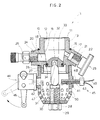
- a discharge valve for extinguishing fluid according to the invention designated as a whole with reference numeral 1, is described with the aid of the figures.
- the valve 1 can be installed on a tank 2.
- the tank 2 contains extinguishing fluid, for example fluid of the liquid halogen type.
- the tank 2 has a capacity of about 14 litres and has brackets 3, disposed in the upper wall thereof, for fixing to a roof or to the upper part of a supporting frame.
- the valve 1 is disposed in the lower wall of the tank 2 for delivery of the extinguishing fluid into the environment beneath.
- the valve 1 can obviously be installed on tanks with different shapes and capacities, such as, for example, tanks in the form of cylinders with a capacity of six litres and large tanks with a capacity of 25 litres.
- the valve 1 comprises a body 10 in nickel-plated brass.
- the body 10 has a substantially cylindrical mouth 11 terminating in an annular abutment surface 20 which extends radially.
- the mouth 11 has an outer thread 13 to engage with an inner thread of an outlet duct 14 ( Figure 1) provided in the lower part of the tank 2.
- a gasket 15 of the OR type is disposed between the outlet duct 14 of the tank and the mouth 13 of the valve and lies in the angle between the mouth 11 and the abutment surface 20.
- the body 10 In its bottom part the body 10 has a hollow cylindrical connector 26 coaxial to the mouth 11.
- the connector 26 has an outer thread for engagement with the inner thread of a discharge nozzle 27.
- the mouth 13 defines an inlet duct 12 that continues with a tapered narrowing duct 16 which communicates with an oblique duct 17 inside the connector for pressure gauge 23 and a radial duct 18 inside the connector 24 for charging valve 25.
- the sensitive part 22 of the pressure gauge 23, being situated inside the duct 17, can measure the pressure of the fluid inside the tank 2. In fact the fluid inside the tank 2 reaches the sensitive part 22 of the pressure gauge through the ducts 14, 12, 16 and 17.
- the charging valve 25 can be connected to an extinguishing fluid distributor.
- the extinguishing fluid from the distributor enters the tank 2 through the ducts 18, 16, 12 and 14.
- the discharge nozzle 27 comprises a substantially cylindrical body, hollow on the inside, open in its upper surface to receive the connector 26 of the valve body 10.
- the nozzle 27 has a threaded central hole 28 to receive the shank of a bolt 29.
- the bolt 29 is tightened, the upper end of the shank reaches a central area inside the nozzle 27.
- a bulb 30 is disposed in the upper part of the shank of the bolt 29.
- the bulb 30 is a heat sensor that is activated and breaks when the temperature reaches about 68°C.
- the bulb 30 has a point 31 with a smaller diameter than the body.
- a closing plate 30 is positioned above the bulb 30.
- the plate 32 has a cavity 33 which is positioned above the point 31 of the bulb.
- a gasket 34 of the OR type is interposed between the side wall of the plate 32 and the inner side wall of the body 10 of the valve. In this manner the extinguishing fluid provided within the ducts 12, 16 of the valve body 10 cannot enter into the nozzle 27.
- the nozzle 27 has two hubs 40, 41 in the side wall, disposed in diametrically opposite positions.
- the hubs 40, 41 define two apertures 42, 43 to receive a manual actuator 44 and an electrical "protractor" actuator 45, respectively.
- the manual actuator 44 has a lever 46 which protrudes outward from the valve 1 so as to be able to be operated manually by a user.
- the lever 46 pushes a small piston 47 disposed inside the aperture 42, radially with respect to the axis of the nozzle 27.
- the small piston 47 passes from a retracted position to an extracted position and strikes against the bulb 30 disposed axially in a central position in the nozzle 27, causing breakage thereof. In this manner the stop plate 32 supported by the bulb 30 falls inside the nozzle 27, allowing the extinguishing fluid to pass inside the body of the nozzle.
- the protractor actuator 45 contains an explosive capsule 48 inserted in the aperture 43. Explosion of the capsule 48 causes the bulb 30 to break and the stop plate 32 to fall inside the nozzle with the consequent discharge of the extinguishing fluid. Operation of the protractor 45 takes place by means of electrical cables 49 which receive a control signal given by the user by means of the push button of a switch or through a remote control. Operation of the protractor can of course be automatic and controlled from control station when certain threshold values are exceeded.
- valve intervenes through breakage of the bulb when the temperature reaches about 68°C, as stated previously.
- the nozzle 27 has thirty-four radial holes 50 for discharge of the extinguishing fluid, arranged in four rows A, B, C and D, disposed circumferentially on the side surface.
- Row A has 12 equidistant holes at an angle of 30°.
- Row B has 10 equidistant holes at an angle of 30° leaving out the two hubs 40 and 41.
- Row C has 6 equidistant holes at an angle of 30° leaving out the two hubs 40 and 41.
- Row D has 6 equidistant holes at an angle of 30° leaving out the two hubs 40 and 41.
- the nozzle 27 may be of the closed type and discharge will take place through one of the two apertures 40, 41, intended respectively for the manual actuator 44 and the protractor 45.
Landscapes
- Health & Medical Sciences (AREA)
- Public Health (AREA)
- Business, Economics & Management (AREA)
- Emergency Management (AREA)
- Lift Valve (AREA)
- Nozzles (AREA)
- Safety Valves (AREA)
- Fluid-Driven Valves (AREA)
- Electrical Discharge Machining, Electrochemical Machining, And Combined Machining (AREA)
Applications Claiming Priority (2)
| Application Number | Priority Date | Filing Date | Title |
|---|---|---|---|
| ITMI001384 | 2000-06-20 | ||
| IT2000MI001384A ITMI20001384A1 (it) | 2000-06-20 | 2000-06-20 | Valvola di scarica per la scarica di fluido estinguente. |
Publications (2)
| Publication Number | Publication Date |
|---|---|
| EP1166824A2 true EP1166824A2 (fr) | 2002-01-02 |
| EP1166824A3 EP1166824A3 (fr) | 2002-08-14 |
Family
ID=11445301
Family Applications (1)
| Application Number | Title | Priority Date | Filing Date |
|---|---|---|---|
| EP01112785A Withdrawn EP1166824A3 (fr) | 2000-06-20 | 2001-05-28 | Soupape de décharge pour l'éjection d'un fluide extincteur |
Country Status (2)
| Country | Link |
|---|---|
| EP (1) | EP1166824A3 (fr) |
| IT (1) | ITMI20001384A1 (fr) |
Cited By (2)
| Publication number | Priority date | Publication date | Assignee | Title |
|---|---|---|---|---|
| WO2005096985A1 (fr) * | 2004-04-06 | 2005-10-20 | Willem Mennega | Dispositif de distribution |
| US20190388720A1 (en) * | 2013-07-12 | 2019-12-26 | Fire Sprinkler Technologies Pty Ltd | Tool and Method for Draining a Fire Sprinkler System and a Fire Sprinkler |
Family Cites Families (9)
| Publication number | Priority date | Publication date | Assignee | Title |
|---|---|---|---|---|
| GB1399749A (en) * | 1971-07-12 | 1975-07-02 | Graviner Ltd | Fire extinguishers and fire extinguishing systems |
| FR2213642A5 (fr) * | 1973-01-10 | 1974-08-02 | Fabricat Entretien Materiel | |
| CH620128A5 (en) * | 1977-04-05 | 1980-11-14 | Cerberus Ag | Triggering device for a valve in a fire-extinguishing system |
| SE413579B (sv) * | 1977-10-20 | 1980-06-09 | Gw Sprinkler As | Vetskespridare for en eldsleckningsanleggning |
| SE413626B (sv) * | 1977-11-23 | 1980-06-16 | Bofors Ab | Sett och anordning for att utlosa en brandskyddssprinkler |
| US4436159A (en) * | 1981-05-01 | 1984-03-13 | Kidde, Inc. | Manual/electric activated squib actuated discharge valve for fire extinguishers |
| GB2214806B (en) * | 1988-02-04 | 1992-01-02 | Fire Fighting Enterprises | Frangible-bulb sprinklers |
| FR2704436B1 (fr) * | 1993-04-27 | 1995-07-21 | Eurofeu Sa | Dispositif de declenchement auxiliaire pour extincteur muni d'une vanne a ampoule en materiau thermocassable. |
| DE4428308C2 (de) * | 1994-08-10 | 1999-03-04 | Peter Dr Ing Lell | Sprinkleranlage |
-
2000
- 2000-06-20 IT IT2000MI001384A patent/ITMI20001384A1/it unknown
-
2001
- 2001-05-28 EP EP01112785A patent/EP1166824A3/fr not_active Withdrawn
Cited By (2)
| Publication number | Priority date | Publication date | Assignee | Title |
|---|---|---|---|---|
| WO2005096985A1 (fr) * | 2004-04-06 | 2005-10-20 | Willem Mennega | Dispositif de distribution |
| US20190388720A1 (en) * | 2013-07-12 | 2019-12-26 | Fire Sprinkler Technologies Pty Ltd | Tool and Method for Draining a Fire Sprinkler System and a Fire Sprinkler |
Also Published As
| Publication number | Publication date |
|---|---|
| ITMI20001384A0 (it) | 2000-06-20 |
| EP1166824A3 (fr) | 2002-08-14 |
| ITMI20001384A1 (it) | 2001-12-20 |
Similar Documents
| Publication | Publication Date | Title |
|---|---|---|
| US5570745A (en) | Relocatable sprinkler assemblage | |
| US10870028B2 (en) | Sprinkler system with a pre-action sprinkler head | |
| US12296211B2 (en) | Fire extinguisher manifold | |
| US11207555B2 (en) | Fire extinguishing and suppression system for vertical walls | |
| US12296207B2 (en) | Suppression and isolation system | |
| KR102141942B1 (ko) | 연기 흡입형 화재감지장치 | |
| US3464497A (en) | Automatic fire extinguisher | |
| JP2001514059A (ja) | 消火器 | |
| US5647438A (en) | Explosion suppressant dispersion nozzle | |
| EP1166824A2 (fr) | Soupape de décharge pour l'éjection d'un fluide extincteur | |
| US2827122A (en) | Fire extinguisher | |
| US4099573A (en) | Sprinkler head | |
| KR101720080B1 (ko) | 건식 스프링클러 헤드 | |
| GB2076652A (en) | Fire extinguisher discharge head | |
| DK2512607T3 (en) | FIRE-FIGHTING DEVICE FOR TRANSFORMING A LIQUID TO A LIQUID MIST | |
| US11189145B2 (en) | Air sampling smoke detector and method of ingesting air therein | |
| US6923265B2 (en) | Submerged thermally sensitive element for an automatic fire sprinkler | |
| CN222400102U (zh) | 一种耐用的消防检测喷烟枪和消防检测系统 | |
| KR101777990B1 (ko) | 소방 안전 점검 설비 | |
| KR102530286B1 (ko) | 공동주택의 소방용 화재 진화 시스템 | |
| KR101999487B1 (ko) | 소화장치 및 소화장치 연동 시스템 | |
| KR830000263Y1 (ko) | 적하식(吊下式) 소화장치 | |
| JPH07204290A (ja) | 予作動式スプリンクラー消火設備 | |
| WO1998028042A1 (fr) | Tete d'extincteur | |
| WO2005096985A1 (fr) | Dispositif de distribution |
Legal Events
| Date | Code | Title | Description |
|---|---|---|---|
| PUAI | Public reference made under article 153(3) epc to a published international application that has entered the european phase |
Free format text: ORIGINAL CODE: 0009012 |
|
| AK | Designated contracting states |
Kind code of ref document: A2 Designated state(s): AT BE CH CY DE DK ES FI FR GB GR IE IT LI LU MC NL PT SE TR |
|
| AX | Request for extension of the european patent |
Free format text: AL;LT;LV;MK;RO;SI |
|
| PUAL | Search report despatched |
Free format text: ORIGINAL CODE: 0009013 |
|
| AK | Designated contracting states |
Kind code of ref document: A3 Designated state(s): AT BE CH CY DE DK ES FI FR GB GR IE IT LI LU MC NL PT SE TR |
|
| AX | Request for extension of the european patent |
Free format text: AL;LT;LV;MK;RO;SI |
|
| AKX | Designation fees paid | ||
| REG | Reference to a national code |
Ref country code: DE Ref legal event code: 8566 |
|
| STAA | Information on the status of an ep patent application or granted ep patent |
Free format text: STATUS: THE APPLICATION IS DEEMED TO BE WITHDRAWN |
|
| 18D | Application deemed to be withdrawn |
Effective date: 20030215 |