EP1166841A2 - Entgasungsvorrichtung - Google Patents
Entgasungsvorrichtung Download PDFInfo
- Publication number
- EP1166841A2 EP1166841A2 EP01305545A EP01305545A EP1166841A2 EP 1166841 A2 EP1166841 A2 EP 1166841A2 EP 01305545 A EP01305545 A EP 01305545A EP 01305545 A EP01305545 A EP 01305545A EP 1166841 A2 EP1166841 A2 EP 1166841A2
- Authority
- EP
- European Patent Office
- Prior art keywords
- deaerator
- oil
- chamber
- chambers
- deaeration
- Prior art date
- Legal status (The legal status is an assumption and is not a legal conclusion. Google has not performed a legal analysis and makes no representation as to the accuracy of the status listed.)
- Withdrawn
Links
Images




Classifications
-
- F—MECHANICAL ENGINEERING; LIGHTING; HEATING; WEAPONS; BLASTING
- F16—ENGINEERING ELEMENTS AND UNITS; GENERAL MEASURES FOR PRODUCING AND MAINTAINING EFFECTIVE FUNCTIONING OF MACHINES OR INSTALLATIONS; THERMAL INSULATION IN GENERAL
- F16N—LUBRICATING
- F16N39/00—Arrangements for conditioning of lubricants in the lubricating system
- F16N39/002—Arrangements for conditioning of lubricants in the lubricating system by deaeration
-
- B—PERFORMING OPERATIONS; TRANSPORTING
- B01—PHYSICAL OR CHEMICAL PROCESSES OR APPARATUS IN GENERAL
- B01D—SEPARATION
- B01D19/00—Degasification of liquids
- B01D19/0042—Degasification of liquids modifying the liquid flow
- B01D19/0052—Degasification of liquids modifying the liquid flow in rotating vessels, vessels containing movable parts or in which centrifugal movement is caused
- B01D19/0057—Degasification of liquids modifying the liquid flow in rotating vessels, vessels containing movable parts or in which centrifugal movement is caused the centrifugal movement being caused by a vortex, e.g. using a cyclone, or by a tangential inlet
-
- B—PERFORMING OPERATIONS; TRANSPORTING
- B01—PHYSICAL OR CHEMICAL PROCESSES OR APPARATUS IN GENERAL
- B01D—SEPARATION
- B01D19/00—Degasification of liquids
- B01D19/0068—General arrangements, e.g. flowsheets
-
- F—MECHANICAL ENGINEERING; LIGHTING; HEATING; WEAPONS; BLASTING
- F16—ENGINEERING ELEMENTS AND UNITS; GENERAL MEASURES FOR PRODUCING AND MAINTAINING EFFECTIVE FUNCTIONING OF MACHINES OR INSTALLATIONS; THERMAL INSULATION IN GENERAL
- F16H—GEARING
- F16H57/00—General details of gearing
- F16H57/04—Features relating to lubrication or cooling or heating
- F16H57/0458—Oil-mist or spray lubrication; Means to reduce foam formation
- F16H57/0461—Means to reduce foam formation
-
- F—MECHANICAL ENGINEERING; LIGHTING; HEATING; WEAPONS; BLASTING
- F16—ENGINEERING ELEMENTS AND UNITS; GENERAL MEASURES FOR PRODUCING AND MAINTAINING EFFECTIVE FUNCTIONING OF MACHINES OR INSTALLATIONS; THERMAL INSULATION IN GENERAL
- F16H—GEARING
- F16H57/00—General details of gearing
- F16H57/04—Features relating to lubrication or cooling or heating
- F16H57/048—Type of gearings to be lubricated, cooled or heated
- F16H57/0487—Friction gearings
- F16H57/0489—Friction gearings with endless flexible members, e.g. belt CVTs
Definitions
- the present invention relates to a deaerator and to a lubrication system including such a deaerator.
- Oil may be used within a single machine for many purposes.
- the oil may be used to lubricate bearings and other rotating parts, to act as a coolant within the generator, and may also act as a control fluid within a speed conversion system used to ensure that a variable input speed is converted to a near constant generator speed.
- it is desirable that the oil contains little entrained air since air bubbles are compressible where as oil is not. This becomes particularly important when oil is being used as a pressurised control fluid since the presence of air bubbles within an actuator system can seriously degrade the system's control performance.
- US5085677 discloses a deaeration device in which a single cylindrical chamber is arranged vertically and has a tangential inlet duct in its lower portion for the introduction of pressurised oil and tangential outlet ducts in its upper portion for the removal of deaerated oil.
- An axially disposed dipper tube is provided in the upper portion of the chamber for the discharge of air from the chamber.
- a deaerator comprising first and second deaeration chambers, each chamber exhibiting substantially rotational symmetry about a respective axis, the chambers deriving a supply of pressurised fluid for deaeration from a shared inlet, and each being arranged such that a portion of the supply of pressurised fluid is introduced tangentially into the chamber.
- the chambers are substantially cylindrical. This makes for a simple manufacturing process.
- the chambers may depart from a strict cylindrical shape if this is deemed desirable and space permits.
- the radius of the chamber may increase in the vicinity of an outlet region in order to slow the oil down prior to discharge.
- the internal profile of the deaerator may be varied around the vicinity of the inlet aperture if it is desired to cause the surface of the oil during deaeration to vary from the parabaloid of revolution which it would assume during deaeration in a cylindrical deaerator.
- the first and second deaeration chambers are formed in a single housing.
- the chambers may be arranged in a side by side configuration with an inlet duct located in the region of the junction between the chambers.
- the inlet duct may contain a separation device, such as a knife edge, in order that the fluid flow from the inlet is directed into the first and second chambers.
- the oil in the chambers forms contra-rotating vortices.
- the contra rotating flows gives the designer freedom of choice to combine the flows such that the oil momentum combines or subtracts if desired, at the outlet of the deaerator.
- each deaerator chamber has a cutaway portion.
- the cutaway portions facing in separate directions.
- Chambers may be added within a single unit.
- three or four chambers may be formed together in a group and a common fluid feed line may be tapped off to each of the chambers in order to admit pressurised fluid into the chamber in a tangential direction near the wall and the base of each chamber.
- a deaeration system comprising a plurality of separation chambers arranged in parallel to receive a source of pressurised fluid for deaeration, wherein a portion of the flow from the source is introduced substantially tangentially into each separation chamber and each chamber has a centrally located air removal path.
- each chamber may be made smaller since the throughput of oil in each chamber, compared to a larger chamber is reduced.
- the reduction in radius of a chamber means that the centrifugal force acting on the oil within the chamber is increased.
- the flow rate through each chamber should be reduced otherwise the increase in centrifugal force which enhances separation could be defeated by the reduced time that the oil would spend in the chamber during the separation process.
- the generator shown in Figure 1 comprises a housing 1 which encloses a continuously variable transmission utilising a belt drive, generally designated 2, a low pressure pump 4, a high pressure pump 6, a generator, generally designated 8, and an oil system disposed throughout the housing 1.
- the belt drive 2 enables the variable speed of an input shaft 10 which receives a drive from a spool of a gas turbine engine to be converted to a near constant speed such that the generator 8 can be run at a near constant speed.
- a first shaft 12 of the belt drive mechanism carries a flange 14 which defines an inclined surface 16 against which a drive belt bears.
- the shaft 12 also carries a coaxially disposed movable flange 20 drivingly connected to the shaft 12 via a splined portion (not shown).
- the movable flange 20 defines a further inclined surface 22 facing towards the surface 16, which surfaces serve to define a V-shaped channel whose width can be varied by changing the axial position of the flange 20 with respect to the fixed flange 14.
- the flange 20 has a circularly symmetric wall 24 extending towards and co-operating with a generally cup shaped element 26 carried on the shaft 12 to define a first hydraulic chamber 28 therebetween which is in fluid flow communication via a control duct (not shown) with an associated control valve.
- a fixed flange 30 and a movable flange 32 are associated with a second shaft 36 and serve to define a second hydraulic control chamber 34.
- a steel segmented belt having a cross-section in the form of a trapezium, with the outer most surface being wider than the inner most surface is used to interconnect the first and second variable ratio pulleys formed between the pairs of fixed and movable flanges, respectively, in order to drivingly connect the flanges.
- each movable flange with respect to the associated fixed flange is controlled by the hydraulic actuators. Since the interconnecting belt is of a fixed width, moving the flanges closer together forces the belt to take a path of increased radial distance.
- the interconnecting belt has a fixed length, and consequently as one movable flange is moved towards its associated fixed flange, the other movable flange must move away from its associated fixed flange in order to ensure that the path from an arbitrary starting point, around one of the pulleys, to the second pulley, around the second pulley and back to the fixed arbitrary starting point remains a constant distance.
- a controller or control system (not shown) which controls both the drive ratio and the compressive load exerted on the belt. It is important that the controller can rapidly change the hydraulic pressures and fluid volumes within the hydraulic chambers 28 and 34, and this requires that the hydraulic fluid must have very little or no air entrained therein. This is because air bubbles are by their very nature compressible and the air bubbles will compress when an increase in hydraulic pressure is made in preference to movement of the actuating surfaces.
- the hydraulic system may require hydraulic pressures in the region of 100 bar. This requires the use of a high pressure pump in order to achieve this hydraulic pressure. The action of pumping fluid to this pressure warms the fluid, and as a result it is not possible, within the limited space available within an aircraft for these components, to utilise a dedicated supply of control fluid since only a small volume of fluid could be provided and this would suffer unacceptable heat rejection problems. Therefore, in order that the heating of the control fluid does not become a problem, the lubricating oil within the generator is also used as the control fluid for the continuously variable transmission. This solves the heat rejection problem, but does require the oil to be highly deaerated prior to its use within the belt control system. However, the oil is also sprayed onto bearings and gears in order to lubricate them and is also used within the rapidly rotating generator 8 as a cooling fluid. These uses allow air to be easily entrained within the oil.
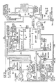
- FIG. 2 schematically illustrates the oil system within the power generation system.
- An oil reservoir 100 acts to contain de-aerated oil.
- the reservoir has a first outlet 102 connected to an inlet of the high pressure pump 6 and a second outlet 104 connected to an inlet of the low pressure pump 4.
- An outlet 106 of the high pressure pump 6 provides oil which is ducted towards a primary piston 110 formed by movable flange 20 and the cup shaped element 26 ( Figure 1) thereby defining the first hydraulic control chamber 28, and a secondary piston 112 (similar to the primary piston) which contains the second hydraulic control chamber 34.
- both the primary piston 110 and the secondary piston 112 can be regarded as being connected between a high pressure supply line 114 and a low pressure return line 116.
- the pressure in the high pressure line 114 is measured by a pressure sensor 118 and supplied to a controller (not shown).
- the controller uses a measurement of oil pressure, aero-engine drive speed and/or generator speed and electrical demand to schedule and/or control the hydraulic pressure acting in the primary and secondary pistons.
- the secondary piston 112 is connected directly to the high pressure line 114.
- the pressure within the high pressure line 114 can be controlled by spilling pressurised lubricant from the high pressure line 114 to the low pressure return line 116 via an electrically controlled pressure control valve 120 connected between the high pressure and low pressure lines, respectively.
- a normally closed pressure return valve 122 is connected between the fluid port to the secondary piston 112 and the low pressure return line 116.
- the valve 122 is normally closed, but is set to open at a predetermined pressure in order to protect the hydraulic system in the event of system over pressure.
- the primary piston 110 receives high pressure fluid from the high pressure line 114 via an electrically operated flow control valve 124.
- the valve 124 is in series with the pressure control valve 120 between the high pressure line 114 and the low pressure line 116, and the primary piston 110 is connected to the node between these valves.
- This configuration of valves means that the pressure control valve 120 can be used to simultaneously increase the pressure in both the primary and secondary pistons in order to prevent belt slippage, whereas the balance of flow rates through the control valve 124 and the pressure control valve 120 sets the relative positions of the primary and secondary pistons. Oil from the low pressure line 116 is returned to the sump 152.
- An outlet 140 of the low pressure pump 4 supplies oil via supply line 142 to oil cooling jets 144 for spraying oil onto the moving parts of the continuously variable transmission, to jets 146 for spraying oil onto the gear train interconnecting the transmission to the generator, to jets 148 for lubricating the windings and bearings within the generator and also along a cooling path 150 for cooling the stator within the generator.
- the generator 8 has a gravity drain to a dry sump 152.
- Oil collecting in the sump 152 is pumped out of the sump by a single scavenge pump 154.
- the output line from the scavenge pump connects with the low pressure return line 136 via an oil strainer 130, a remotely mounted oil cooler 132 and an oil filter 134.
- a pressure fill connector 156 is in fluid flow communication with the low pressure return line 194 in order to allow the oil system to be filled.
- An oil cooler by-pass valve 158 is connected between the output from the strainer 130 and the line 136 in order to by-pass the oil cooler and oil filter during cold start or in the event of cooler, filter or external line blockage.
- the oil by-pass valve is normally closed and set to open at a predetermined over pressure.
- a drain plug 170 is provided in the reservoir, similarly a drain plug 172 is provided for the sump and a pressure operated vent valve 174 is provided in the generator in order to relieve the excess pressure occurring within the generator.
- a manually operated vent valve 176 is provided to vent pressure from the generator.
- An automatic air inlet valve 178 is provided to allow air to enter the generator via an injector pump 196 to provide positive internal pressure.
- the oil in the return line 136 flows with a velocity of up to 6ms -1 . This flow is sufficient to enable the oil to be deaerated within a vortex aerator.
- Vortex deaerators work by exploiting the difference in density between the oil and an air bubble entrained therein.
- the oil under pressure, is forced through a restricted aperture in order to increase its velocity.
- the aperture is arranged to be tangential with the cylindrical wall of the aerator in order that the oil is spun into a helical path within the aerator.
- the rate of entry of oil into the aerator has to be matched by the rate of exit of oil from the aerator.
- This oil has a vertical motion superimposed on its rotating motion, the velocity of the vertical motion being that necessary to ensure that the flow rate from the deaerator matches the flow rate into the deaerator. From this it follows that, if the radius of the deaerator is halved, the axial velocity of oil up the wall of the deaerator is increased, approximately by a factor of 2, such that the product of separating force by separation time remains substantially invariant.
- the provision of a plurality of smaller diameter deaerators each handling a proportion of the total deaeration task provides for better deaeration of the oil than in the prior art.
- the level of deaeration is important within the context of speed control systems using continuously variable transmission having belt drive of the type described herein before.
- FIG. 3 schematically illustrates a suitable deaerator which can be placed within the oil reservoir 100.
- the deaerator comprises two cylinders 200 and 202 defined by cylindrical walls 204 and 206, respectively.
- the walls 204 and 206 abut and merge together in a central region 208.
- An inlet duct 210 extends horizontally from the base of the cylinders.
- the inlet duct is bifurcated by a knife edge such that it divides into two fluid flow paths.
- Each path tapers from a cylindrical to a rectangular cross-section, with the long axis of the rectangle extending vertically.
- the rectangular channel shape intersects with the circular cross-section of the inner of the chambers in order to define an injection region which is tangential with the walls of the chambers.
- fluid introduced at pressure through duct 210 is split equally into fluid flow paths and injected into the chambers 200 and 202 at increased velocity and tangentially in order to form a vortex.
- each wall 204 and 206 have semicircular portions cut out from the wall to define semicircular lips of reduced height.
- One of the lips is indicated generally as 212. As shown in Figure 3, the lips face away from each other. These lips provide a controlled discharge route for oil at the uppermost region of the deaerators.
- Each deaerator also has an axially positioned dip tube 214 and 216 which extends downward into the aerator and finishes at a plane just above the uppermost portion of the tangential channel.
- the dip tubes 214 and 216 extend above the upper surface of the aerator, and in use pass through and extend above a baffle plate.
- the position of the deaerator within the oil reservoir 100 is shown in greater detail in Figure 4.
- the deaerator 200 is shown sectioned through the line A-A' of Figure 3, and consequently the rectangular nature of the nozzle 220 is clearly shown as is the relative position of the dip tube 214, and the fact that its lower end 218 lies just above the uppermost portion of the channel 220 through which oil is introduced into the chamber.
- An upper end 222 of the dip tube vents into a plenum chamber 224 defined above a baffle plate 226.
- the plenum chamber vents to the generator via a duct 228.
- the reservoir includes a drain 230 and an overflow 232.
- the overflow is significant since it enables the oil system to be filled in a single operation.
- overflow 232 is opened and then oil is injected via connector 156 of Figure 2. This causes oil to flow from the injector up one arm of the low pressure return line through the strainer 130, the oil cooler 132 the filter 134 and into the reservoir via the line 136 and the vortex deaerator.
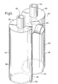
- FIG. 5 is a schematic representation of a modified twin vortex deaerator.
- the deaerator indicated generally as 300 is similar to the deaerator described with respect to Figure 3, except that it is now in an inverted configuration.
- the deaerator comprises two cylinders 302 and 304 defined by cylindrical walls 306 and 308, respectively.
- the walls 306 and 308 abut and merge together in a central region 310.
- An inlet duct 312 extends horizontally into an upper portion of the cylinders.
- the inlet duct is bifurcated by a knife edge such that it divides into two fluid flow paths. Each path tapers from a cylindrical to a rectangular cross section with the long axis of the rectangle extending vertically.
- the rectangular channel shape intersects with the circular cross section of the inner of the chambers in order to define an injection region which is tangential with the walls of the chambers.
- each cylinder is closed by a respective wall 320 and 322 through which an associated dip tube 324 and 326 extends.
- each wall 306 and 308 have semicircular portions removed therefrom such that, when the deaerator is disposed inside a oil reservoir with end wall 330 and 332 of the cylinders contacting a wall of the oil reservoir the semicircular portions serve to define oil exit paths such that oil can escape from the deaerator.
- Figure 6 schematically shows the modified deaerator in position within an oil reservoir.
- the oil reservoir is similar to that described with respect to Figure 4, and like reference numerals are used for like parts.
- the main significant difference is that the dip tube 324 is comparatively shorter than the corresponding dip tube 214 shown in Figure 4.
- the deaerator 306 is, in use, completely submerged in lubricant within the chamber 340. Lubricant fed in from the scavenge pump is injected via a vertically disposed aperture 342 positioned towards the upper wall 320 of the deaerator. Oil exits the deaerator via an exit aperture 344.
- Oil received from the scavenge pump will have been passed through an oil cooler and therefore it can be expected to be cooler than the oil already present in the oil reservoir (since heat will lead into the oil reservoir from the generator and gear box surrounding it) and consequently the oil will naturally tend to sink thereby displacing all the oil.
- the operation of the vortex deaerator and the oil reservoir is substantially as already hereinbefore described.
Landscapes
- Engineering & Computer Science (AREA)
- General Engineering & Computer Science (AREA)
- Chemical & Material Sciences (AREA)
- Chemical Kinetics & Catalysis (AREA)
- Mechanical Engineering (AREA)
- Oil, Petroleum & Natural Gas (AREA)
- General Details Of Gearings (AREA)
- Centrifugal Separators (AREA)
Applications Claiming Priority (2)
| Application Number | Priority Date | Filing Date | Title |
|---|---|---|---|
| GB0016179 | 2000-06-30 | ||
| GBGB0016179.4A GB0016179D0 (en) | 2000-06-30 | 2000-06-30 | Deaerator |
Publications (2)
| Publication Number | Publication Date |
|---|---|
| EP1166841A2 true EP1166841A2 (de) | 2002-01-02 |
| EP1166841A3 EP1166841A3 (de) | 2002-08-07 |
Family
ID=9894832
Family Applications (1)
| Application Number | Title | Priority Date | Filing Date |
|---|---|---|---|
| EP01305545A Withdrawn EP1166841A3 (de) | 2000-06-30 | 2001-06-26 | Entgasungsvorrichtung |
Country Status (3)
| Country | Link |
|---|---|
| US (1) | US20020007736A1 (de) |
| EP (1) | EP1166841A3 (de) |
| GB (1) | GB0016179D0 (de) |
Cited By (6)
| Publication number | Priority date | Publication date | Assignee | Title |
|---|---|---|---|---|
| US6575709B2 (en) * | 2000-06-30 | 2003-06-10 | Goodrich Control Systems | Pumps |
| EP2535097A1 (de) * | 2011-06-17 | 2012-12-19 | Hamilton Sundstrand Corporation | Luftabscheider und Leitungsanordnung |
| CN104033591A (zh) * | 2013-03-04 | 2014-09-10 | 通用汽车环球科技运作有限责任公司 | 用于对变速器中的流体进行除气的系统 |
| WO2015108803A1 (en) * | 2014-01-14 | 2015-07-23 | Caterpillar Inc. | Deaerator apparatus |
| EP2963249A1 (de) * | 2014-07-01 | 2016-01-06 | United Technologies Corporation | Gasturbinenmotor mit getriebefan und ölentlüfter |
| RU2606536C2 (ru) * | 2011-12-12 | 2017-01-10 | Кейтерпиллар Инк. | Диффузорное устройство для текучей среды и рабочая машина с таким устройством |
Families Citing this family (15)
| Publication number | Priority date | Publication date | Assignee | Title |
|---|---|---|---|---|
| JP4128085B2 (ja) * | 2002-05-22 | 2008-07-30 | 株式会社小松製作所 | 液体タンク |
| JP2004036169A (ja) * | 2002-07-02 | 2004-02-05 | Komatsu Ltd | 作業車両 |
| CA2701915C (en) * | 2006-10-20 | 2015-06-30 | The University Of Kentucky Research Foundation | Fluid scrubber and spray booth including the fluid scrubber |
| US7531026B2 (en) * | 2006-11-13 | 2009-05-12 | Ise Corporation | Deaeration device and method of use |
| US7985283B2 (en) * | 2008-04-09 | 2011-07-26 | GM Global Technology Operations LLC | System for de-aerating a hydraulic fluid in a transmission |
| US8230835B2 (en) * | 2009-03-10 | 2012-07-31 | Honeywell International Inc. | Emergency engine lubrication systems and methods |
| CN102313666A (zh) * | 2010-07-03 | 2012-01-11 | 聚光科技(杭州)股份有限公司 | 一种液体样品除泡器 |
| US9782695B2 (en) | 2014-02-11 | 2017-10-10 | Schaeffler Technologies AG & Co. KG | De-aeration device for a hydraulically actuated variable valve actuation system |
| US9795898B2 (en) * | 2015-03-31 | 2017-10-24 | Jci Cyclonics Ltd. | Cyclonic separator system |
| US10330131B2 (en) | 2016-03-24 | 2019-06-25 | Schaeffler Technologies AG & Co. KG | Hydraulic fluid de-aeration device |
| US20180036653A1 (en) * | 2016-08-03 | 2018-02-08 | Jci Cyclonic Technologies Ltd. | Dual cyclone separator |
| JP2018123743A (ja) * | 2017-01-31 | 2018-08-09 | アイシン精機株式会社 | 車両用オイル供給装置 |
| JP7312693B2 (ja) * | 2019-12-25 | 2023-07-21 | マーレジャパン株式会社 | 気泡分離器、および気泡分離器を備える自動車の流体回路 |
| CN115059645B (zh) * | 2022-08-19 | 2022-12-13 | 徐工集团工程机械股份有限公司科技分公司 | 一种具有强制除气结构的液压油箱 |
| US12352209B1 (en) * | 2024-06-25 | 2025-07-08 | Pratt & Whitney Canada Corp. | Aircraft engine fluid separation system and method |
Family Cites Families (6)
| Publication number | Priority date | Publication date | Assignee | Title |
|---|---|---|---|---|
| BE489468A (de) * | 1948-04-21 | |||
| GB894417A (en) * | 1959-01-28 | 1962-04-18 | Hermann Jaeckering | Centrifugal separators for separating or grading solid mixtures |
| GB8805755D0 (en) * | 1988-03-10 | 1988-04-07 | Shell Int Research | Apparatus for separation of solids from mixture of solids & fluid |
| GB2248562B (en) * | 1990-10-01 | 1994-08-24 | F E Beaumont Ltd | A chimney installation |
| EP0646380B1 (de) * | 1993-09-01 | 1997-06-25 | Fresenius AG | Luftabscheider |
| AUPP624298A0 (en) * | 1998-09-30 | 1998-10-22 | Alcos Technologies Pty Ltd | Cyclonic evaporator |
-
2000
- 2000-06-30 GB GBGB0016179.4A patent/GB0016179D0/en not_active Ceased
-
2001
- 2001-06-26 EP EP01305545A patent/EP1166841A3/de not_active Withdrawn
- 2001-06-29 US US09/893,409 patent/US20020007736A1/en not_active Abandoned
Cited By (14)
| Publication number | Priority date | Publication date | Assignee | Title |
|---|---|---|---|---|
| US6575709B2 (en) * | 2000-06-30 | 2003-06-10 | Goodrich Control Systems | Pumps |
| EP2535097A1 (de) * | 2011-06-17 | 2012-12-19 | Hamilton Sundstrand Corporation | Luftabscheider und Leitungsanordnung |
| US8444751B2 (en) | 2011-06-17 | 2013-05-21 | Hamilton Sundstrand Corporation | Deaerator and conduit assembly |
| RU2606536C2 (ru) * | 2011-12-12 | 2017-01-10 | Кейтерпиллар Инк. | Диффузорное устройство для текучей среды и рабочая машина с таким устройством |
| CN104033591A (zh) * | 2013-03-04 | 2014-09-10 | 通用汽车环球科技运作有限责任公司 | 用于对变速器中的流体进行除气的系统 |
| CN104033591B (zh) * | 2013-03-04 | 2017-04-26 | 通用汽车环球科技运作有限责任公司 | 用于对变速器中的流体进行除气的系统 |
| WO2015108803A1 (en) * | 2014-01-14 | 2015-07-23 | Caterpillar Inc. | Deaerator apparatus |
| EP2963249A1 (de) * | 2014-07-01 | 2016-01-06 | United Technologies Corporation | Gasturbinenmotor mit getriebefan und ölentlüfter |
| US9976490B2 (en) | 2014-07-01 | 2018-05-22 | United Technologies Corporation | Geared gas turbine engine with oil deaerator |
| US20180238242A1 (en) * | 2014-07-01 | 2018-08-23 | United Technologies Corporation | Geared gas turbine engine with oil deaerator |
| US20190063330A1 (en) * | 2014-07-01 | 2019-02-28 | United Technologies Corporation | Geared gas turbine engine with oil deaerator |
| EP3693564A1 (de) * | 2014-07-01 | 2020-08-12 | United Technologies Corporation | Verzahnter gasturbinenmotor mit ölentlüfter |
| US11725589B2 (en) | 2014-07-01 | 2023-08-15 | Raytheon Technologies Corporation | Geared gas turbine engine with oil deaerator |
| EP4575205A3 (de) * | 2014-07-01 | 2025-09-10 | RTX Corporation | Gasturbinenmotor mit getriebe und ölentlüfter |
Also Published As
| Publication number | Publication date |
|---|---|
| US20020007736A1 (en) | 2002-01-24 |
| GB0016179D0 (en) | 2000-08-23 |
| EP1166841A3 (de) | 2002-08-07 |
Similar Documents
| Publication | Publication Date | Title |
|---|---|---|
| EP1166841A2 (de) | Entgasungsvorrichtung | |
| US11073041B2 (en) | Jet engine | |
| US20170096910A1 (en) | Turbine Engine Oil Reservoir with Deaerator | |
| EP1167859A2 (de) | Ölanlage | |
| US11566563B2 (en) | Oil distribution system for an engine | |
| CN110462182B (zh) | 用于涡轮机的离心脱气器 | |
| US11692669B2 (en) | Oil tank filler cap integrated into the de-aerator | |
| SE456969B (sv) | Foerfarande foer avluftande av slutna vaetskecirkulationssystem samt anordning foer genomfoerande av foerfarandet | |
| CA3105211A1 (en) | Integral centrifugal degasser | |
| CN113018911B (zh) | 气泡分离器和包括气泡分离器的用于汽车的流体回路 | |
| CA2990903C (en) | Air-oil separation apparatus | |
| EP4067629A1 (de) | Öltank für flugzeugmotor | |
| US2747514A (en) | Scavenge line centrifuge | |
| SE1550684A1 (sv) | Apparatus for cleaning crank case gases | |
| US20020000479A1 (en) | Fluid reservoir | |
| US20250277458A1 (en) | Static de-aerator and lubricant system | |
| EP0423396A2 (de) | Vorrichtung zur Entfernung von Gasblasen aus einer Flüssigkeit | |
| JP2021042754A (ja) | 気泡分離器、および気泡分離器を備える自動車の流体回路 | |
| US8444751B2 (en) | Deaerator and conduit assembly | |
| RU209901U1 (ru) | Устройство воздухоотделителя | |
| EP4025321B1 (de) | Blasenseparator und flüssigkeitskreislauf mit blasenseparator für ein kraftfahrzeug | |
| RU2530968C1 (ru) | Маслосистема авиационного газотурбинного двигателя | |
| US20030146052A1 (en) | Oil system and a generator including such an oil system | |
| KR20180094956A (ko) | 유체 커플링 |
Legal Events
| Date | Code | Title | Description |
|---|---|---|---|
| PUAI | Public reference made under article 153(3) epc to a published international application that has entered the european phase |
Free format text: ORIGINAL CODE: 0009012 |
|
| AK | Designated contracting states |
Kind code of ref document: A2 Designated state(s): AT BE CH CY DE DK ES FI FR GB GR IE IT LI LU MC NL PT SE TR |
|
| AX | Request for extension of the european patent |
Free format text: AL;LT;LV;MK;RO;SI |
|
| PUAL | Search report despatched |
Free format text: ORIGINAL CODE: 0009013 |
|
| AK | Designated contracting states |
Kind code of ref document: A3 Designated state(s): AT BE CH CY DE DK ES FI FR GB GR IE IT LI LU MC NL PT SE TR |
|
| AX | Request for extension of the european patent |
Free format text: AL;LT;LV;MK;RO;SI |
|
| RIC1 | Information provided on ipc code assigned before grant |
Free format text: 7B 01D 19/00 A, 7B 04C 3/04 B, 7B 04C 5/28 B, 7F 16N 39/00 B |
|
| 17P | Request for examination filed |
Effective date: 20030124 |
|
| AKX | Designation fees paid |
Designated state(s): DE FR GB |
|
| STAA | Information on the status of an ep patent application or granted ep patent |
Free format text: STATUS: THE APPLICATION HAS BEEN WITHDRAWN |
|
| 18W | Application withdrawn |
Effective date: 20030714 |