EP1166875A2 - Rotor avec des outils à découpage, en particulier pour les déchiqueteurs - Google Patents
Rotor avec des outils à découpage, en particulier pour les déchiqueteurs Download PDFInfo
- Publication number
- EP1166875A2 EP1166875A2 EP01110067A EP01110067A EP1166875A2 EP 1166875 A2 EP1166875 A2 EP 1166875A2 EP 01110067 A EP01110067 A EP 01110067A EP 01110067 A EP01110067 A EP 01110067A EP 1166875 A2 EP1166875 A2 EP 1166875A2
- Authority
- EP
- European Patent Office
- Prior art keywords
- rotor
- support
- flat
- tool
- Prior art date
- Legal status (The legal status is an assumption and is not a legal conclusion. Google has not performed a legal analysis and makes no representation as to the accuracy of the status listed.)
- Withdrawn
Links
- 230000000284 resting effect Effects 0.000 claims 5
- 239000000463 material Substances 0.000 description 8
- 230000008878 coupling Effects 0.000 description 2
- 238000010168 coupling process Methods 0.000 description 2
- 238000005859 coupling reaction Methods 0.000 description 2
- 230000006866 deterioration Effects 0.000 description 2
- 230000035939 shock Effects 0.000 description 2
- 239000002699 waste material Substances 0.000 description 2
- 238000010521 absorption reaction Methods 0.000 description 1
- 238000009826 distribution Methods 0.000 description 1
- 238000005516 engineering process Methods 0.000 description 1
- 230000000670 limiting effect Effects 0.000 description 1
- 238000012423 maintenance Methods 0.000 description 1
- 238000003801 milling Methods 0.000 description 1
- 238000012986 modification Methods 0.000 description 1
- 230000004048 modification Effects 0.000 description 1
- 238000004064 recycling Methods 0.000 description 1
- 239000007779 soft material Substances 0.000 description 1
- 238000009827 uniform distribution Methods 0.000 description 1
- 238000003466 welding Methods 0.000 description 1
Images

Classifications
-
- B—PERFORMING OPERATIONS; TRANSPORTING
- B02—CRUSHING, PULVERISING, OR DISINTEGRATING; PREPARATORY TREATMENT OF GRAIN FOR MILLING
- B02C—CRUSHING, PULVERISING, OR DISINTEGRATING IN GENERAL; MILLING GRAIN
- B02C13/00—Disintegrating by mills having rotary beater elements ; Hammer mills
- B02C13/26—Details
- B02C13/28—Shape or construction of beater elements
- B02C13/2804—Shape or construction of beater elements the beater elements being rigidly connected to the rotor
-
- B—PERFORMING OPERATIONS; TRANSPORTING
- B02—CRUSHING, PULVERISING, OR DISINTEGRATING; PREPARATORY TREATMENT OF GRAIN FOR MILLING
- B02C—CRUSHING, PULVERISING, OR DISINTEGRATING IN GENERAL; MILLING GRAIN
- B02C18/00—Disintegrating by knives or other cutting or tearing members which chop material into fragments
- B02C18/06—Disintegrating by knives or other cutting or tearing members which chop material into fragments with rotating knives
- B02C18/14—Disintegrating by knives or other cutting or tearing members which chop material into fragments with rotating knives within horizontal containers
- B02C18/145—Disintegrating by knives or other cutting or tearing members which chop material into fragments with rotating knives within horizontal containers with knives spaced axially and circumferentially on the periphery of a cylindrical rotor unit
-
- B—PERFORMING OPERATIONS; TRANSPORTING
- B02—CRUSHING, PULVERISING, OR DISINTEGRATING; PREPARATORY TREATMENT OF GRAIN FOR MILLING
- B02C—CRUSHING, PULVERISING, OR DISINTEGRATING IN GENERAL; MILLING GRAIN
- B02C18/00—Disintegrating by knives or other cutting or tearing members which chop material into fragments
- B02C18/06—Disintegrating by knives or other cutting or tearing members which chop material into fragments with rotating knives
- B02C18/16—Details
- B02C18/18—Knives; Mountings thereof
Definitions
- the present invention relates to a rotor particularly for shredders.
- Shredders are now widely used especially in the field of disposal of municipal waste, waste materials and of recycling.
- the rotor can be of the smooth type or can be provided with circumferential grooves which usually have a V-shaped profile.
- rotors provided with circumferential grooves having a V-shaped profile are particularly suitable for shredding soft materials, owing to the tendency of such materials to accumulate at the back of the cutting inserts.
- the cutting inserts are usually associated by screws with the supporting element, which is accommodated in the grooves and is welded thereat.
- the supporting elements thus rest on the grooves and are joined thereto with a permanent coupling provided by welding.
- Constraints linked to the weldability of the material of the supporting element do not allow to use tempered or wear-resistant material for the element in order to avoid early deterioration of its dimensional and structural characteristics.
- the aim of the present invention is to provide a rotor particularly for shredders which solves or substantially reduces the problems of conventional rotors.
- an object of the present invention is to provide a rotor having tools and tool supporting elements which can absorb in an optimum manner the stresses to which they are subjected during use.
- Another object of the invention is to provide a rotor by virtue of which there are no constraints regarding the use of material to provide the tool holder.
- Another object of the invention is to provide a rotor in which the tool and the tool holder can be replaced and/or interchanged easily and rapidly.
- Another object is to provide a rotor which can be manufactured by means of known equipment and technologies and at low costs.
- a rotor with cutting tools particularly for shredders of the type provided, on their active surface, with circumferential grooves having a substantially V-shaped profile characterized in that it comprises at least one tool fixed detachably to a corresponding support which is in turn fixed detachably to the rotor, said support comprising a flat base portion and a back portion which rest on a complementarily shaped flat pocket provided in the rotor in the direction of an imaginary chord which lies on a plane being perpendicular to the rotation axis of the rotor.
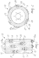
- a rotor with cutting elements particularly for shredding machines is generally designated by the reference numeral 10.
- the structure 10 comprises a rotor 11 on whose active surface there are a plurality of substantially V-shaped circumferential grooves which form in succession troughs 12 and crests 13.
- the rotor 11 is further provided with at least one and preferably a plurality of cutting tools 14.
- the tools 14 are plates provided with two mutually opposite surfaces which have a square plan shape and are much larger than the other surfaces; one surface 16a is flat and is designed to rest on a support which is generally designated by the reference numeral 17, and one surface 16b is concave and adapted to form four cutting edges 15, of which two, upon assembly, protrude partially from the dimensions of the rotor 11.
- the tools can be plates provided with two mutually opposite flat surfaces having a square plan shape which are much larger than the other surfaces or can be plates having a circular plan shape.
- the support 17 has a tapering upper portion 18, a flat base portion 19, a back portion 20 with rounded edges, and a front portion 21 for accommodating a tool 14.
- the tool 14 rests on the front portion 21 with the flat surface 16a and with two contiguous lateral surfaces 22.
- the tool 14 is arranged on a plane which is perpendicular to the lower portion 19 of the support 17, with its lateral surfaces 22 inclined at 45° with respect to the rotor axis.
- the tool 14 is fixed to the support 17 by means of a removable coupling, i.e., a screw 23, which passes through the tool 14 and the support 17 in corresponding through holes 24a and 24b, and a locking nut 25 which is arranged at the back portion 20 of the support 17.
- a removable coupling i.e., a screw 23, which passes through the tool 14 and the support 17 in corresponding through holes 24a and 24b, and a locking nut 25 which is arranged at the back portion 20 of the support 17.
- the tool 14 has two consecutive cutting edges, generally designated by the reference numeral 15a, which lie outside the dimensions of the rotor 11 and shred the material by cooperating with a contrast blade which is rigidly coupled to the frame of the shredder and is not shown in the figure but is in any case of a per se known type.
- the support 17 is arranged on the rotor 11 at a flat pocket generally designated by the reference numeral 26.
- the pocket 26 is formed by milling in the direction of an imaginary chord which lies on a plane being perpendicular to the longitudinal axis of the rotor 11.
- the pocket 26 comprises a first flat portion and a second flat portion, designated by the reference numerals 27 and 28 respectively, which are separate and are formed by a shoulder 29.
- the shoulder 29 is substantially U-shaped.
- the support 17 rests with the base portion 19 on the first portion 27 of the pocket 26 and with the back portion 20 on the shoulder 29.
- the support 17 is fixed to the rotor 11 by means of two screws 30 which pass through corresponding holes 31 of the support 17 and are arranged at right angles to the pocket 26.
- the second portion 28 of the flat pocket 26 allows to easily access the locking nut 25 for possible replacement of the tool 14.
- the support 17 Being accommodated in a seat formed by the first portion 27 of the pocket 26 and by the shoulder 29, the support 17 is capable of absorbing in an optimum manner the shocks to which it is subjected during use, further ensuring uniform impact distribution.
- the possibility to remove and/or replace easily the support 17 simply by removing two screws 30 ensures very short maintenance times and avoids problems linked to the replacement of conventional supports, which are welded to the rotor body, thus entailing the cutting and unwelding of said support.
- this support 17 can be made of tempered or wear-resistant material in order to avoid early deterioration of its dimensional and structural characteristics.
- the tool 14 is fixed by means of a through screw 23 which allows immediate interchangeability thereof.
- the materials and the dimensions, so long as they are compatible with the contingent use, may be any according to requirements.
Landscapes
- Engineering & Computer Science (AREA)
- Food Science & Technology (AREA)
- Crushing And Pulverization Processes (AREA)
- Polishing Bodies And Polishing Tools (AREA)
Applications Claiming Priority (2)
| Application Number | Priority Date | Filing Date | Title |
|---|---|---|---|
| ITPD20000116 IT1315442B1 (it) | 2000-05-09 | 2000-05-09 | Struttura di rotore a utensili taglienti particolarmente per macchinetrituratrici. |
| ITPD000116 | 2000-05-09 |
Publications (2)
| Publication Number | Publication Date |
|---|---|
| EP1166875A2 true EP1166875A2 (fr) | 2002-01-02 |
| EP1166875A3 EP1166875A3 (fr) | 2003-02-12 |
Family
ID=11451964
Family Applications (1)
| Application Number | Title | Priority Date | Filing Date |
|---|---|---|---|
| EP01110067A Withdrawn EP1166875A3 (fr) | 2000-05-09 | 2001-04-27 | Rotor avec des outils à découpage, en particulier pour les déchiqueteurs |
Country Status (2)
| Country | Link |
|---|---|
| EP (1) | EP1166875A3 (fr) |
| IT (1) | IT1315442B1 (fr) |
Cited By (3)
| Publication number | Priority date | Publication date | Assignee | Title |
|---|---|---|---|---|
| ITBO20090690A1 (it) * | 2009-10-23 | 2011-04-24 | C M G S P A | Perfezionamenti in macchine per triturare materiali vari come blocchi di plastica, residui di legno, cartonage e cosi' via. |
| US9144803B2 (en) | 2011-06-24 | 2015-09-29 | Vecoplan Llc | Shredder with multi-point cutters |
| EP2590749A4 (fr) * | 2010-07-07 | 2017-06-28 | BMH Technology Oy | Trépan à lames pour rotor de broyeur |
Family Cites Families (4)
| Publication number | Priority date | Publication date | Assignee | Title |
|---|---|---|---|---|
| DE29515768U1 (de) * | 1995-10-04 | 1995-12-07 | Holz-, Metall-, Abfall-, Recyclingtechnik Gmbh, 79576 Weil Am Rhein | Schneidwerkzeug für Zerkleinerungsmaschinen |
| DE29714130U1 (de) * | 1997-08-07 | 1997-10-09 | Unterwurzacher Patentverwertungsgesellschaft M.B.H., Kuchl | Zerkleinerungsvorrichtung |
| NL1009850C2 (nl) * | 1998-08-12 | 2000-02-15 | Visno Maschf B V | Inrichting voor het verkleinen en vermalen van grof materiaal. |
| JP2001079437A (ja) * | 1999-09-13 | 2001-03-27 | Ujiie Seisakusho:Kk | 回転カッタ及び切断処理装置 |
-
2000
- 2000-05-09 IT ITPD20000116 patent/IT1315442B1/it active
-
2001
- 2001-04-27 EP EP01110067A patent/EP1166875A3/fr not_active Withdrawn
Cited By (5)
| Publication number | Priority date | Publication date | Assignee | Title |
|---|---|---|---|---|
| ITBO20090690A1 (it) * | 2009-10-23 | 2011-04-24 | C M G S P A | Perfezionamenti in macchine per triturare materiali vari come blocchi di plastica, residui di legno, cartonage e cosi' via. |
| WO2011048030A1 (fr) * | 2009-10-23 | 2011-04-28 | C.M.G. S.P.A. | Améliorations apportées à des machines permettant de déchiqueter divers matériaux, tels que des blocs de plastique, des résidus ligneux, des emballages en carton, etc. |
| US20120199678A1 (en) * | 2009-10-23 | 2012-08-09 | Cassani Stefano | Improvements in machines for shredding various materials such as blocks of plastics, wood residues, cardboard packaging and so forth |
| EP2590749A4 (fr) * | 2010-07-07 | 2017-06-28 | BMH Technology Oy | Trépan à lames pour rotor de broyeur |
| US9144803B2 (en) | 2011-06-24 | 2015-09-29 | Vecoplan Llc | Shredder with multi-point cutters |
Also Published As
| Publication number | Publication date |
|---|---|
| ITPD20000116A1 (it) | 2001-11-09 |
| IT1315442B1 (it) | 2003-02-10 |
| EP1166875A3 (fr) | 2003-02-12 |
Similar Documents
| Publication | Publication Date | Title |
|---|---|---|
| JP4749340B2 (ja) | 回転式研削機及びカッター取付け構造 | |
| US8967515B2 (en) | Tool unit and cutting or punching tool for a comminution device, and a device equipped therewith | |
| CN103153469B (zh) | 粉碎装置的刀架 | |
| ES2298186T3 (es) | Diente de fresado para una maquina trituradora. | |
| KR101556832B1 (ko) | 밀링 커터 및 후방 돌기를 가지는 컷팅 삽입체 | |
| JP2014008505A (ja) | 連続したナイフを有する粉砕ロータを備えた粉砕装置 | |
| AU2012252274B2 (en) | Bottom grate of a crusher or drum chipper and method of producing the bottom grate | |
| CA1066038A (fr) | Porte-lames pour dechiqueteuse de grumes | |
| EP0761089B1 (fr) | Contre-couteau, spécialement pour couper du fourrage | |
| EP1166875A2 (fr) | Rotor avec des outils à découpage, en particulier pour les déchiqueteurs | |
| US20090189004A1 (en) | Comminuting device with counter-rotating rotors | |
| CN103153468B (zh) | 梳齿支持装置 | |
| US20090140091A1 (en) | Cutting Tool for Comminuting Devices | |
| ES2813087T3 (es) | Máquina trituradora y herramienta para utilizar en una máquina trituradora | |
| US20020047062A1 (en) | Granulator | |
| CN103374816A (zh) | 切刀 | |
| CA2929212C (fr) | Module dilacerateur destine a un appareil dilacerateur servant a dilacerer un materiau d'alimentation, dans un panier a couteau particulier | |
| ES2200461T3 (es) | Cuchillas mecanicas. | |
| ES2746050T3 (es) | Máquina trituradora | |
| KR101761192B1 (ko) | 볼트 및 이를 구비한 커터조립체 | |
| JPH11114437A (ja) | シュレッダ及びハンマミル用回転子 | |
| JP2000189824A (ja) | せん断破砕機 | |
| JP3137617B2 (ja) | 破砕機のロータ | |
| JPH09271684A (ja) | 破砕機用ハンマ | |
| JP3236940U (ja) | チッパー用粉砕デバイス及びチッパー |
Legal Events
| Date | Code | Title | Description |
|---|---|---|---|
| PUAI | Public reference made under article 153(3) epc to a published international application that has entered the european phase |
Free format text: ORIGINAL CODE: 0009012 |
|
| AK | Designated contracting states |
Kind code of ref document: A2 Designated state(s): AT BE CH CY DE DK ES FI FR GB GR IE IT LI LU MC NL PT SE TR |
|
| AX | Request for extension of the european patent |
Free format text: AL;LT;LV;MK;RO;SI |
|
| PUAL | Search report despatched |
Free format text: ORIGINAL CODE: 0009013 |
|
| AK | Designated contracting states |
Designated state(s): AT BE CH CY DE DK ES FI FR GB GR IE IT LI LU MC NL PT SE TR |
|
| AX | Request for extension of the european patent |
Extension state: AL LT LV MK RO SI |
|
| RIC1 | Information provided on ipc code assigned before grant |
Ipc: 7B 02C 18/14 B Ipc: 7B 02C 18/18 B Ipc: 7B 02C 13/06 B Ipc: 7B 02C 13/28 A |
|
| 17P | Request for examination filed |
Effective date: 20030721 |
|
| 17Q | First examination report despatched |
Effective date: 20030916 |
|
| AKX | Designation fees paid |
Designated state(s): DE |
|
| STAA | Information on the status of an ep patent application or granted ep patent |
Free format text: STATUS: THE APPLICATION HAS BEEN WITHDRAWN |
|
| 18W | Application withdrawn |
Effective date: 20040310 |