EP1166902A2 - Dispositif pour nettoyer des caisses - Google Patents
Dispositif pour nettoyer des caisses Download PDFInfo
- Publication number
- EP1166902A2 EP1166902A2 EP01115069A EP01115069A EP1166902A2 EP 1166902 A2 EP1166902 A2 EP 1166902A2 EP 01115069 A EP01115069 A EP 01115069A EP 01115069 A EP01115069 A EP 01115069A EP 1166902 A2 EP1166902 A2 EP 1166902A2
- Authority
- EP
- European Patent Office
- Prior art keywords
- conveyor
- transport
- guide
- boxes
- upward
- Prior art date
- Legal status (The legal status is an assumption and is not a legal conclusion. Google has not performed a legal analysis and makes no representation as to the accuracy of the status listed.)
- Granted
Links
- 238000004140 cleaning Methods 0.000 title claims abstract description 19
- 239000007788 liquid Substances 0.000 claims abstract description 5
- 230000007704 transition Effects 0.000 claims description 7
- 238000007654 immersion Methods 0.000 description 4
- 238000005406 washing Methods 0.000 description 4
- 239000000463 material Substances 0.000 description 2
- 238000000034 method Methods 0.000 description 2
- 239000007921 spray Substances 0.000 description 2
- 239000010935 stainless steel Substances 0.000 description 2
- 238000012546 transfer Methods 0.000 description 2
- 230000006978 adaptation Effects 0.000 description 1
- 239000000654 additive Substances 0.000 description 1
- 230000000712 assembly Effects 0.000 description 1
- 238000000429 assembly Methods 0.000 description 1
- 235000013361 beverage Nutrition 0.000 description 1
- 230000015572 biosynthetic process Effects 0.000 description 1
- 230000000903 blocking effect Effects 0.000 description 1
- 238000005260 corrosion Methods 0.000 description 1
- 230000007797 corrosion Effects 0.000 description 1
- 230000001419 dependent effect Effects 0.000 description 1
- 238000011161 development Methods 0.000 description 1
- 230000018109 developmental process Effects 0.000 description 1
- 239000013505 freshwater Substances 0.000 description 1
- 238000012986 modification Methods 0.000 description 1
- 230000004048 modification Effects 0.000 description 1
- 230000010355 oscillation Effects 0.000 description 1
- 239000007787 solid Substances 0.000 description 1
- 229910001220 stainless steel Inorganic materials 0.000 description 1
- XLYOFNOQVPJJNP-UHFFFAOYSA-N water Substances O XLYOFNOQVPJJNP-UHFFFAOYSA-N 0.000 description 1
Images



Classifications
-
- B—PERFORMING OPERATIONS; TRANSPORTING
- B08—CLEANING
- B08B—CLEANING IN GENERAL; PREVENTION OF FOULING IN GENERAL
- B08B9/00—Cleaning hollow articles by methods or apparatus specially adapted thereto
- B08B9/08—Cleaning containers, e.g. tanks
- B08B9/0861—Cleaning crates, boxes or the like
Definitions
- the invention relates to a device according to the preamble of claim 1.
- a device (DE 44 00 871-A1) is also known in which the cleaning boxes on a conveyor through the interior of a housing be moved on the handling of the boxes with different aqueous Treatment or cleaning media takes place and the u.a. of horizontal conveyor or Transport routes is formed, which in turn or upward in Form of jaw conveyors are interconnected.
- the object of the invention is to show a device for cleaning boxes, which enables intensive cleaning of boxes of different sizes allows.
- a device is according to the Claim 1 trained.
- the invention allows i.a. an adaptation of the Device or its conveyor on boxes of different sizes and / or Height. Different designs are available for the device according to the invention conceivable.
- At least one arranged above the transport level, in Transport direction (A) extending guide element for the boxes on one of the Transport plane facing away from the side provided, namely with a first adjustment or Lifting device to adjust the height of the distance that the Has guide element from the transport level, is adjustable, namely preferably from the outside of the housing.
- the at least one is in the conveying direction Transport route preceding the upward or reversing conveyor is provided in which the boxes one parallel to the transport plane and perpendicular to the Conveying direction axis are turned, with the transition between a box guide (32) is provided for the upward conveyor and the transport route, the at least one, for example formed by at least one slide rail Sliding element for the side of the boxes facing the transport plane forms over the the boxes slide from the upward conveyor onto the transport level of the transport route and that with one end extends at least to an exit of the upward conveyor and is arranged with another end in the region of the transport route, and the sliding element at one end by a second adjusting device is adjustable relative to the transport level.
- Transport or conveyor routes are formed, which are one by one Clamp jaw conveyors formed upward or reversing conveyors with each other are connected, the conveyor width by adjusting the distance between the two Elements of the respective jaw conveyor is changeable, a third Adjustment device is provided with the lateral guide railing at least one the conveyor lines are adjustable with the elements of the jaw conveyor.
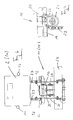
- the one shown in the figures and generally designated 1 there Cleaning machine is used to clean boxes 2 and 2a, which are used to hold Containers, for example bottles (box 2) or cans (box 2a) are intended.
- the machine 1 essentially consists of an elongated or cuboid housing 3, which has an interior or treatment room 4th encloses in which the for washing and cleaning the boxes 2 and 2a necessary functional elements and units (especially immersion bath and Spray nozzles) are housed.
- the interior 4 is not, for example illustrated, provided on one long side of the housing 3, i.e. Man - sized doors with large windows through which the way the Machine 1 can be monitored easily and clearly.
- this conveyor device consists of essentially of three arranged vertically above one another in the vertical direction horizontal conveyor lines 9 - 11, on which the boxes moved in the conveying direction A. are and of which the lowest conveyor section 9 is designed as an immersion bath in which the boxes 2 and 2a to be cleaned in a cleaning liquid to be submerged.
- the middle transport route 10 and the upper transport route 11 are each of independent, endlessly driven conveyor chains 12 ( Figure 6) formed, each with its upper, horizontal length a footprint for the boxes 2 and 2a form and the transport level TE of the transport route define.
- the conveyor lines 10 and 11 continue to have each on the long sides lateral guide railing 13, which extends in the horizontal direction along the concerned transport route extends parallel to the direction of conveyance A.
- Hinged belt chains designed conveyor belts 12 are each driven so that the necessary conveying direction A results for boxes 2 and 2a, i.e. at the for 1 selected representation on the transport route 10 from right to left and on the transport route 11 from left to right.
- a turning or Upward conveyors 14 and 15 are provided, in which the boxes 2 and 2a are turned be, so that in the illustrated embodiment, the boxes on their bottom are fed up the box inlet 6, which is designed as an immersion bath Run through transport route 9 in this orientation, then via the upward conveyor 14 turned, i.e. with the box floor lying on top of the transport route 10 are handed over and turned again from there via the upward conveyor 15, again with the floor below on the transport route 11 to the Box outlet 9 arrive.
- spray nozzles 16 for the respective Washing or treatment liquid water with cleaning additives as well Fresh water for rinsing, etc.
- the upward conveyors 14 and 15 are each designed as jaw conveyors, in which the boxes 2 and 2a are held laterally by clamping on clamping jaws, the driven on revolving and guided on frames or supports 43 Jaw bands 44 are provided (Fig. 7).
- Such jaw conveyors are known to the person skilled in the art.
- the boxes 2 and 2a have different Size and height, with the boxes 2 usual in the embodiment shown Bottle crates for holding beverage bottles and the crates 2a from one suitable material, for example trays made of plastic for holding Cans are.
- Adjustment device 18 is provided for each Guide railing 17 a separate one in the illustrated embodiment Adjustment device 18 is provided. This essentially consists of one upper, designed as a rod lifting rail 19, which is shown in the Embodiment formed by a C or U profile and above the associated one Guide rail 17 is arranged such that the open side of this profile after below, i.e. points in the direction of the guide rail 17.
- the lifting rail 19 with their longitudinal extent parallel to the associated guide rail 17 and together with this in the central plane M is in the longitudinal direction, i.e. in horizontal direction parallel to the conveying direction A by a predetermined stroke (Double arrow C) slidable.
- a frame 20 of the housing 3 several rollers 21 freely rotatable about axes perpendicular to the central plane M, and on flat arms 22 projecting downward from frame elements 20 Rollers 21 is the rail 19, between the arms 22 and thus through secured against slipping down sideways.
- each adjusting device 18 there are several chains designed as roller chains 23 each fastened with one end, in the embodiment shown in each adjusting device 18 a total of three chains at regular intervals such that there is a chain 23 in the region of each end of the rail 19 or the associated guide rail 17 and a chain 23 in the middle of each Rail 19 or guide rail 17 is located.
- Each chain 23 is with her upper end between the legs of the U or C profile of the lifting rail 19th held (attachment point 24) and via this attachment point 24 adjacent roller 21 guided so that each chain 23 down over this roller 21 hangs.
- Each chain 23 is still with its lower end at 25 at the top of the associated guide rail 17 attached.
- all chains 23 extend each lifting or Adjustment device 18 each in the same direction via its fastening point 24 adjacent role 21, specifically in the illustration selected for FIG. 1 starting from the upper attachment point 24 counterclockwise by about a quarter of the scope of the associated role 21. Furthermore, the arrangement is so hit that in the one end position of the stroke C, the lowest position of the Guide rail 17 corresponds to the upper attachment point 24 on the roller 21 or is in close proximity to this role while in the other Extreme position of the stroke C, the upper position of the guide rail 17th corresponds, the upper attachment point 24 from the associated roller 21 one has a greater distance. In both cases, the respective chain 23 is over the associated role 21 performed.
- the formation of the lifting rail 19 as a C or U profile and the attachment of the chains 23 inside this profile have the advantage that the lifting rail 19 on the rollers 21 rests and the chains 23 are also guided over the same rollers 21.
- the C-profile can also be another profile, for example a for the lifting rails 19 Solid profile or a tubular profile with a square or rectangular cross-section be used, this profile then in the region of the rollers 21 with a is open towards the bottom recess for the chains 23 such that in A U- or C-shaped cross section is obtained in the region of the recess. Still is it is possible to provide the rollers 21 with a circumferential groove for the chains 23, the respective lifting rail then lies laterally from this groove on the roller.
- the respective Lifting rail 19 in the direction of the double arrow C by turning one of the Outside of the housing 3 provided dial 27 shifted and thus the Height of the associated guide rail 17 can be set.
- a drive for example a cable 26
- the respective Lifting rail 19 in the direction of the double arrow C by turning one of the Outside of the housing 3 provided dial 27 shifted and thus the Height of the associated guide rail 17 can be set.
- a common actuator for example setting wheel 27 to operate.
- this setting can also by motor, for example by an electric motor or another motor Actuator or drive take place.
- the guide rails 17 are in the illustrated embodiment when the Boxes 2 and 2a come into contact with these guide rails with their Mass weight against the boxes and exist in the illustrated Embodiment with a hollow or tubular profile closed on the circumference square cross section.
- the joint 28 is designed so that there is a pivoting between the Allows guide rails 17 and 17a about an axis perpendicular to the center plane M.
- the joint 29 formed on the bearing 30 is designed so that it pivots an axis perpendicular to the central plane M and at the same time also a radial one Allows moving in the horizontal direction.
- the hinge 29 is a pin-slot joint.
- the guide rails 17a prevent bottle crates 2 or 2a at the beginning of the respective guide rail 17 by possibly Blocking against the end of this guide rail there, i.e. by the guide rails 17a become those in the respective conveyor section 9, 10 and 11 incoming boxes 2 and 2a thus reliably under the associated guide rail 17 headed.
- the guide rails 17a also stabilize the associated guide rail 17 is reached, in particular also against one unwanted oscillation around an axis parallel to the conveying direction A.
- the guide rails 17a also each consist of a tubular profile square cross section.
- the boxes 2, 2a which have a very different height can have, from the transport route 10 to the subsequent Upward conveyor 15 passed in a position that corresponds to the positioning of this Boxes on the transport route 10 corresponds to, i.e. the boxes are with their open Side in the area of the upward conveyor 15 lying outside with a radial distance from the central axis 31 of the semicircular path of movement
- Upward conveyor arranged (radial distance) corresponds to the distance that the Transport or conveying plane of the transport route 10 from this central axis 31 having.
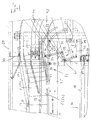
- an adjustable box guide 32 provided over which the boxes 2 and 2a with their underside sliding on the Conveyor belt or on the flat top chain 12 of the transport route 11 and through which a gentle and in particular also low-noise transfer of Boxes of smaller height, for example boxes 2a, are reached.
- the box guide 32 consists essentially of two of a tube profile formed slide rail 33, each at one end by means of a joint 34 a frame 35 of the transport route 11 are articulated, that is pivotable about a horizontal axis perpendicular to the central plane M or to the direction of transport A.
- the frame 35 forms the guide for the flat top chain 12 and the storage for the guide and deflection wheels of this chain.
- the joints 34 of the two slide rails 33 are arranged axially. With her free, curved ends extend the slide rails 33 into the upward conveyor 15 into it.
- the slide rails 33 are on both sides of the flat top chain 12 intended.
- Approximately in the middle are the two slide rails 33 on the underside a crossbar 36 connected with its longitudinal extent parallel to the axis of Joints 34 lies.
- a lever 38 is articulated at one end, the other end by means of a joint 39 is articulated on an arm 40 'of an angle lever 40.
- the angle lever 40 is by means of a joint 41 is articulated on a frame part 20 of the housing 3.
- the free end the other arm 40 "of the angle lever 40 is via a tension member 42 with the Lifting rail 19 connected to the adjustment device 18 with which the Height adjustment of the guide rail 17 of the underlying transport route 10 he follows.
- the lever 38 and the arms 40 'and 42 "of the angle lever 40 lie in one plane parallel to the central plane M.
- the joints 37, 39 and 41 lie with their joint axes perpendicular to this median plane.
- the arrangement is still such that when Adjustment of the lifting rail 19 for the guide rail 17 of the transport route 10 in In order to lower this guide rail 17, the two slide rails 33 around the Joints 34 are pivoted with their free ends upwards or at one Raising the mentioned guide rail 17 swiveling the slide rails 33 downwards.
- the setting of the box guide 32 thus takes place via the common setting element for the height adjustment of the guide rail 17 of the box guide 32 in Transport direction A preceding transport route 10.
- This adjustment is carried out via spindles 45 can be operated via a common drive, for example via a manual one Drive on the outside of the housing 3.
- a width adjustment at least the Transport routes 10 and 11 or the guide rail 13 there can be reached each guide railing 13 at both ends via a lever arrangement 46 with a Frame element 43 is drivingly connected.
- the lever arrangement 46 consists of a lever 47, which over that of the respective Transport route 10 or 11 facing away from the outside of the guide railing 13 obliquely stands out and at one end by means of a hinge 48 on the guide rail and the other end by means of a joint 49 on a frame part 20 of the housing 3 is articulated. In the middle is the lever 47 via a joint 50 with one end Control lever 51 connected, the other end via a hinge 52 with the Frame part 43 is articulated.
- the joint axes of the joints 48, 49, 50 and 52 are vertical axes, respectively.
- the guide rails 17, 17a and the elements of the Adjustment device 18 are in particular the guide rails 17, 17a and the elements of the Adjustment device 18, the box guide 32 and the elements of Lever assemblies 46 made of corrosion-resistant material, preferably made of stainless steel or corrosion-resistant steel.
- the roles 21 of the Adjustment devices 18 are preferably made of a suitable plastic.
Landscapes
- Engineering & Computer Science (AREA)
- Mechanical Engineering (AREA)
- Washing And Drying Of Tableware (AREA)
- Cleaning In General (AREA)
- Apparatus For Disinfection Or Sterilisation (AREA)
- Cleaning By Liquid Or Steam (AREA)
- Framework For Endless Conveyors (AREA)
- Control Of Driving Devices And Active Controlling Of Vehicle (AREA)
Applications Claiming Priority (2)
| Application Number | Priority Date | Filing Date | Title |
|---|---|---|---|
| DE20011170U | 2000-06-30 | ||
| DE20011170U DE20011170U1 (de) | 2000-06-30 | 2000-06-30 | Vorrichtung zum Reinigen von Kästen |
Publications (3)
| Publication Number | Publication Date |
|---|---|
| EP1166902A2 true EP1166902A2 (fr) | 2002-01-02 |
| EP1166902A3 EP1166902A3 (fr) | 2003-07-09 |
| EP1166902B1 EP1166902B1 (fr) | 2006-08-02 |
Family
ID=7943226
Family Applications (1)
| Application Number | Title | Priority Date | Filing Date |
|---|---|---|---|
| EP01115069A Expired - Lifetime EP1166902B1 (fr) | 2000-06-30 | 2001-06-21 | Dispositif pour nettoyer des caisses |
Country Status (3)
| Country | Link |
|---|---|
| EP (1) | EP1166902B1 (fr) |
| AT (1) | ATE334752T1 (fr) |
| DE (2) | DE20011170U1 (fr) |
Cited By (1)
| Publication number | Priority date | Publication date | Assignee | Title |
|---|---|---|---|---|
| CN118543614A (zh) * | 2023-02-24 | 2024-08-27 | 克朗斯股份公司 | 用于清洁容器的装置和用于操作该装置的方法 |
Family Cites Families (7)
| Publication number | Priority date | Publication date | Assignee | Title |
|---|---|---|---|---|
| US2744531A (en) * | 1951-12-17 | 1956-05-08 | Dole Eng Co James | Container washing apparatus |
| JPH07112894B2 (ja) * | 1986-10-31 | 1995-12-06 | 株式会社小松製作所 | タ−ンオ−バ装置 |
| DE4038239C2 (de) | 1990-11-30 | 1993-11-25 | Kettner Verpackungsmaschf | Vorrichtung zum Wenden von Mehrweggebinden |
| DE4400871C2 (de) * | 1993-09-19 | 2000-11-02 | Ludwig Bohrer | Vorrichtung zum Waschen bzw. Reinigen von Flaschenkästen |
| DE19542457C1 (de) | 1995-11-14 | 1997-04-03 | Bohrer Maschinenbau Gmbh | Anlage zum Reinigen von Industriebehältern |
| JPH09295610A (ja) * | 1996-05-02 | 1997-11-18 | Shin Etsu Polymer Co Ltd | 長尺物の整列装置 |
| DE10017290C2 (de) | 2000-04-07 | 2002-04-18 | Holzmann Wilhelm | Vorrichtung und Verfahren zur Reinigung von Transportbehältern |
-
2000
- 2000-06-30 DE DE20011170U patent/DE20011170U1/de not_active Expired - Lifetime
-
2001
- 2001-06-21 DE DE50110587T patent/DE50110587D1/de not_active Expired - Lifetime
- 2001-06-21 AT AT01115069T patent/ATE334752T1/de not_active IP Right Cessation
- 2001-06-21 EP EP01115069A patent/EP1166902B1/fr not_active Expired - Lifetime
Cited By (2)
| Publication number | Priority date | Publication date | Assignee | Title |
|---|---|---|---|---|
| CN118543614A (zh) * | 2023-02-24 | 2024-08-27 | 克朗斯股份公司 | 用于清洁容器的装置和用于操作该装置的方法 |
| EP4420801A1 (fr) * | 2023-02-24 | 2024-08-28 | Krones AG | Dispositif de nettoyage de récipients et procédé de fonctionnement du dispositif |
Also Published As
| Publication number | Publication date |
|---|---|
| EP1166902B1 (fr) | 2006-08-02 |
| EP1166902A3 (fr) | 2003-07-09 |
| DE20011170U1 (de) | 2001-03-01 |
| DE50110587D1 (de) | 2006-09-14 |
| ATE334752T1 (de) | 2006-08-15 |
Similar Documents
| Publication | Publication Date | Title |
|---|---|---|
| EP0721808B1 (fr) | Machine de nettoyage de récipients | |
| DE3789149T2 (de) | Fördereinrichtung. | |
| DE2943769C2 (fr) | ||
| EP1059225B1 (fr) | Procédé et appareillage pour convoyer des carosseries de véhicule à travers un bain de traitement | |
| EP0485937A1 (fr) | Dispositif de groupement | |
| EP1383696A1 (fr) | Dispositif transporteur pour acheminer des pieces d'usinage a travers une zone de traitement en vue du traitement de surface desdites pieces d'usinage | |
| DE3016940A1 (de) | Vorrichtung zum ausrichten aufrechtstehender gefaesse mit unrundem querschnitt | |
| DE10210942B4 (de) | Anlage zum Behandeln, insbesondere zum kataphoretischen Tauchlackieren, von Gegenständen, insbesondere von Fahrzeugkarosserien | |
| DE3137623C1 (fr) | ||
| DE4400871C2 (de) | Vorrichtung zum Waschen bzw. Reinigen von Flaschenkästen | |
| DE19513221A1 (de) | Reinigungsmaschine für Gefäße | |
| EP1166902B1 (fr) | Dispositif pour nettoyer des caisses | |
| DE4330702A1 (de) | Verstellbare Geländerstütze sowie Förderstrecke mit verstellbarem Geländer | |
| DE4027433A1 (de) | Verfahren und einrichtung zum drehen eines gegenstandes | |
| EP1059223A1 (fr) | Berceaux pour le transport de pièces à travailler, en particulier de carosseries de véhicules, et dispositif de rotation pour retourner ces berceaux | |
| DE19542457C1 (de) | Anlage zum Reinigen von Industriebehältern | |
| EP2342150B1 (fr) | Convoyeur sans fin avec dispositif pour nettoyer le convoyeur | |
| DE2531507C2 (de) | Vorrichtung zum Sortieren und Klassieren lebender Fische | |
| DE60100214T2 (de) | Schwenkstation für die Fördervorrichtung einer Behandlungsanlage | |
| DE2825741A1 (de) | Vorrichtung zum ein- und aushaengen von stoffballen o.dgl. | |
| CH645142A5 (en) | Apparatus for the retention treatment of a broad-guided textile web | |
| DE10331982B4 (de) | Anlage zum Reinigen von Kästen, insbesondere Flaschenkästen | |
| DE8909050U1 (de) | Maschine zum Reinigen von Flaschenkästen | |
| DE8435932U1 (de) | Vorrichtung zum waschen von flaschenkaesten | |
| DE20112237U1 (de) | Vorrichtung zum Reinigen von Flaschenkästen |
Legal Events
| Date | Code | Title | Description |
|---|---|---|---|
| PUAI | Public reference made under article 153(3) epc to a published international application that has entered the european phase |
Free format text: ORIGINAL CODE: 0009012 |
|
| AK | Designated contracting states |
Kind code of ref document: A2 Designated state(s): AT BE CH CY DE DK ES FI FR GB GR IE IT LI LU MC NL PT SE TR |
|
| AX | Request for extension of the european patent |
Free format text: AL;LT;LV;MK;RO;SI |
|
| PUAL | Search report despatched |
Free format text: ORIGINAL CODE: 0009013 |
|
| AK | Designated contracting states |
Designated state(s): AT BE CH CY DE DK ES FI FR GB GR IE IT LI LU MC NL PT SE TR |
|
| AX | Request for extension of the european patent |
Extension state: AL LT LV MK RO SI |
|
| 17P | Request for examination filed |
Effective date: 20030808 |
|
| AKX | Designation fees paid |
Designated state(s): AT BE CH CY DE DK ES FI FR GB GR IE IT LI LU MC NL PT SE TR |
|
| GRAP | Despatch of communication of intention to grant a patent |
Free format text: ORIGINAL CODE: EPIDOSNIGR1 |
|
| GRAS | Grant fee paid |
Free format text: ORIGINAL CODE: EPIDOSNIGR3 |
|
| GRAA | (expected) grant |
Free format text: ORIGINAL CODE: 0009210 |
|
| AK | Designated contracting states |
Kind code of ref document: B1 Designated state(s): AT BE CH CY DE DK ES FI FR GB GR IE IT LI LU MC NL PT SE TR |
|
| PG25 | Lapsed in a contracting state [announced via postgrant information from national office to epo] |
Ref country code: IT Free format text: LAPSE BECAUSE OF FAILURE TO SUBMIT A TRANSLATION OF THE DESCRIPTION OR TO PAY THE FEE WITHIN THE PRESCRIBED TIME-LIMIT;WARNING: LAPSES OF ITALIAN PATENTS WITH EFFECTIVE DATE BEFORE 2007 MAY HAVE OCCURRED AT ANY TIME BEFORE 2007. THE CORRECT EFFECTIVE DATE MAY BE DIFFERENT FROM THE ONE RECORDED. Effective date: 20060802 Ref country code: IE Free format text: LAPSE BECAUSE OF FAILURE TO SUBMIT A TRANSLATION OF THE DESCRIPTION OR TO PAY THE FEE WITHIN THE PRESCRIBED TIME-LIMIT Effective date: 20060802 Ref country code: NL Free format text: LAPSE BECAUSE OF FAILURE TO SUBMIT A TRANSLATION OF THE DESCRIPTION OR TO PAY THE FEE WITHIN THE PRESCRIBED TIME-LIMIT Effective date: 20060802 Ref country code: FI Free format text: LAPSE BECAUSE OF FAILURE TO SUBMIT A TRANSLATION OF THE DESCRIPTION OR TO PAY THE FEE WITHIN THE PRESCRIBED TIME-LIMIT Effective date: 20060802 Ref country code: GB Free format text: LAPSE BECAUSE OF FAILURE TO SUBMIT A TRANSLATION OF THE DESCRIPTION OR TO PAY THE FEE WITHIN THE PRESCRIBED TIME-LIMIT Effective date: 20060802 |
|
| REG | Reference to a national code |
Ref country code: GB Ref legal event code: FG4D Free format text: NOT ENGLISH |
|
| REG | Reference to a national code |
Ref country code: CH Ref legal event code: EP |
|
| REG | Reference to a national code |
Ref country code: IE Ref legal event code: FG4D Free format text: LANGUAGE OF EP DOCUMENT: GERMAN |
|
| REF | Corresponds to: |
Ref document number: 50110587 Country of ref document: DE Date of ref document: 20060914 Kind code of ref document: P |
|
| PG25 | Lapsed in a contracting state [announced via postgrant information from national office to epo] |
Ref country code: DK Free format text: LAPSE BECAUSE OF FAILURE TO SUBMIT A TRANSLATION OF THE DESCRIPTION OR TO PAY THE FEE WITHIN THE PRESCRIBED TIME-LIMIT Effective date: 20061102 Ref country code: SE Free format text: LAPSE BECAUSE OF FAILURE TO SUBMIT A TRANSLATION OF THE DESCRIPTION OR TO PAY THE FEE WITHIN THE PRESCRIBED TIME-LIMIT Effective date: 20061102 |
|
| PG25 | Lapsed in a contracting state [announced via postgrant information from national office to epo] |
Ref country code: ES Free format text: LAPSE BECAUSE OF FAILURE TO SUBMIT A TRANSLATION OF THE DESCRIPTION OR TO PAY THE FEE WITHIN THE PRESCRIBED TIME-LIMIT Effective date: 20061113 |
|
| NLV1 | Nl: lapsed or annulled due to failure to fulfill the requirements of art. 29p and 29m of the patents act | ||
| PG25 | Lapsed in a contracting state [announced via postgrant information from national office to epo] |
Ref country code: PT Free format text: LAPSE BECAUSE OF FAILURE TO SUBMIT A TRANSLATION OF THE DESCRIPTION OR TO PAY THE FEE WITHIN THE PRESCRIBED TIME-LIMIT Effective date: 20070102 |
|
| GBV | Gb: ep patent (uk) treated as always having been void in accordance with gb section 77(7)/1977 [no translation filed] |
Effective date: 20060802 |
|
| REG | Reference to a national code |
Ref country code: IE Ref legal event code: FD4D |
|
| EN | Fr: translation not filed | ||
| PLBE | No opposition filed within time limit |
Free format text: ORIGINAL CODE: 0009261 |
|
| STAA | Information on the status of an ep patent application or granted ep patent |
Free format text: STATUS: NO OPPOSITION FILED WITHIN TIME LIMIT |
|
| 26N | No opposition filed |
Effective date: 20070503 |
|
| BERE | Be: lapsed |
Owner name: BOHRER, LUDWIG Effective date: 20070630 |
|
| PG25 | Lapsed in a contracting state [announced via postgrant information from national office to epo] |
Ref country code: MC Free format text: LAPSE BECAUSE OF NON-PAYMENT OF DUE FEES Effective date: 20070630 |
|
| REG | Reference to a national code |
Ref country code: CH Ref legal event code: PL |
|
| PG25 | Lapsed in a contracting state [announced via postgrant information from national office to epo] |
Ref country code: BE Free format text: LAPSE BECAUSE OF NON-PAYMENT OF DUE FEES Effective date: 20070630 |
|
| PG25 | Lapsed in a contracting state [announced via postgrant information from national office to epo] |
Ref country code: CH Free format text: LAPSE BECAUSE OF NON-PAYMENT OF DUE FEES Effective date: 20070630 Ref country code: FR Free format text: LAPSE BECAUSE OF FAILURE TO SUBMIT A TRANSLATION OF THE DESCRIPTION OR TO PAY THE FEE WITHIN THE PRESCRIBED TIME-LIMIT Effective date: 20070511 Ref country code: GR Free format text: LAPSE BECAUSE OF FAILURE TO SUBMIT A TRANSLATION OF THE DESCRIPTION OR TO PAY THE FEE WITHIN THE PRESCRIBED TIME-LIMIT Effective date: 20061103 Ref country code: LI Free format text: LAPSE BECAUSE OF NON-PAYMENT OF DUE FEES Effective date: 20070630 |
|
| PG25 | Lapsed in a contracting state [announced via postgrant information from national office to epo] |
Ref country code: AT Free format text: LAPSE BECAUSE OF NON-PAYMENT OF DUE FEES Effective date: 20070621 |
|
| PG25 | Lapsed in a contracting state [announced via postgrant information from national office to epo] |
Ref country code: FR Free format text: LAPSE BECAUSE OF FAILURE TO SUBMIT A TRANSLATION OF THE DESCRIPTION OR TO PAY THE FEE WITHIN THE PRESCRIBED TIME-LIMIT Effective date: 20060802 |
|
| PG25 | Lapsed in a contracting state [announced via postgrant information from national office to epo] |
Ref country code: LU Free format text: LAPSE BECAUSE OF NON-PAYMENT OF DUE FEES Effective date: 20070621 Ref country code: CY Free format text: LAPSE BECAUSE OF FAILURE TO SUBMIT A TRANSLATION OF THE DESCRIPTION OR TO PAY THE FEE WITHIN THE PRESCRIBED TIME-LIMIT Effective date: 20060802 |
|
| PG25 | Lapsed in a contracting state [announced via postgrant information from national office to epo] |
Ref country code: TR Free format text: LAPSE BECAUSE OF FAILURE TO SUBMIT A TRANSLATION OF THE DESCRIPTION OR TO PAY THE FEE WITHIN THE PRESCRIBED TIME-LIMIT Effective date: 20060802 |
|
| PGFP | Annual fee paid to national office [announced via postgrant information from national office to epo] |
Ref country code: DE Payment date: 20180731 Year of fee payment: 18 |
|
| REG | Reference to a national code |
Ref country code: DE Ref legal event code: R119 Ref document number: 50110587 Country of ref document: DE |
|
| PG25 | Lapsed in a contracting state [announced via postgrant information from national office to epo] |
Ref country code: DE Free format text: LAPSE BECAUSE OF NON-PAYMENT OF DUE FEES Effective date: 20200101 |