EP1166926A2 - Verfahren zum Formen von biokompatiblen Komponenten - Google Patents
Verfahren zum Formen von biokompatiblen Komponenten Download PDFInfo
- Publication number
- EP1166926A2 EP1166926A2 EP01122088A EP01122088A EP1166926A2 EP 1166926 A2 EP1166926 A2 EP 1166926A2 EP 01122088 A EP01122088 A EP 01122088A EP 01122088 A EP01122088 A EP 01122088A EP 1166926 A2 EP1166926 A2 EP 1166926A2
- Authority
- EP
- European Patent Office
- Prior art keywords
- flexible container
- stock
- biocompatible
- container
- biocompatible component
- Prior art date
- Legal status (The legal status is an assumption and is not a legal conclusion. Google has not performed a legal analysis and makes no representation as to the accuracy of the status listed.)
- Granted
Links
- 238000000034 method Methods 0.000 title claims abstract description 58
- 239000000560 biocompatible material Substances 0.000 claims abstract description 19
- 238000010438 heat treatment Methods 0.000 claims abstract description 11
- 239000000843 powder Substances 0.000 claims description 35
- 239000000463 material Substances 0.000 claims description 31
- 239000011248 coating agent Substances 0.000 claims description 17
- 238000000576 coating method Methods 0.000 claims description 17
- 239000007921 spray Substances 0.000 claims description 14
- 239000010935 stainless steel Substances 0.000 claims description 10
- 229910001220 stainless steel Inorganic materials 0.000 claims description 10
- 229910052710 silicon Inorganic materials 0.000 claims description 6
- 239000010703 silicon Substances 0.000 claims description 6
- 238000007789 sealing Methods 0.000 claims description 5
- 229910052782 aluminium Inorganic materials 0.000 claims description 4
- XAGFODPZIPBFFR-UHFFFAOYSA-N aluminium Chemical compound [Al] XAGFODPZIPBFFR-UHFFFAOYSA-N 0.000 claims description 4
- 230000004888 barrier function Effects 0.000 claims description 4
- 239000011888 foil Substances 0.000 claims description 4
- 229920000728 polyester Polymers 0.000 claims description 4
- 229920002635 polyurethane Polymers 0.000 claims description 4
- 239000004814 polyurethane Substances 0.000 claims description 4
- 230000009477 glass transition Effects 0.000 claims description 2
- 230000002708 enhancing effect Effects 0.000 claims 1
- 238000000465 moulding Methods 0.000 claims 1
- XKRFYHLGVUSROY-UHFFFAOYSA-N Argon Chemical compound [Ar] XKRFYHLGVUSROY-UHFFFAOYSA-N 0.000 description 16
- -1 polyethylene Polymers 0.000 description 14
- 239000004698 Polyethylene Substances 0.000 description 13
- 229920000573 polyethylene Polymers 0.000 description 13
- 239000011324 bead Substances 0.000 description 11
- 239000007789 gas Substances 0.000 description 11
- RVTZCBVAJQQJTK-UHFFFAOYSA-N oxygen(2-);zirconium(4+) Chemical compound [O-2].[O-2].[Zr+4] RVTZCBVAJQQJTK-UHFFFAOYSA-N 0.000 description 11
- 229920002492 poly(sulfone) Polymers 0.000 description 11
- 229910001928 zirconium oxide Inorganic materials 0.000 description 11
- YMWUJEATGCHHMB-UHFFFAOYSA-N Dichloromethane Chemical compound ClCCl YMWUJEATGCHHMB-UHFFFAOYSA-N 0.000 description 9
- 239000004699 Ultra-high molecular weight polyethylene Substances 0.000 description 9
- 229920000785 ultra high molecular weight polyethylene Polymers 0.000 description 9
- 229910052786 argon Inorganic materials 0.000 description 8
- 238000001816 cooling Methods 0.000 description 8
- 210000000629 knee joint Anatomy 0.000 description 7
- IJGRMHOSHXDMSA-UHFFFAOYSA-N Atomic nitrogen Chemical compound N#N IJGRMHOSHXDMSA-UHFFFAOYSA-N 0.000 description 6
- 230000008901 benefit Effects 0.000 description 6
- 239000002131 composite material Substances 0.000 description 6
- 229920001169 thermoplastic Polymers 0.000 description 6
- 239000004416 thermosoftening plastic Substances 0.000 description 6
- 230000003247 decreasing effect Effects 0.000 description 5
- 230000001419 dependent effect Effects 0.000 description 5
- 239000002657 fibrous material Substances 0.000 description 5
- XLYOFNOQVPJJNP-UHFFFAOYSA-N water Chemical compound O XLYOFNOQVPJJNP-UHFFFAOYSA-N 0.000 description 5
- 229920000049 Carbon (fiber) Polymers 0.000 description 4
- RYGMFSIKBFXOCR-UHFFFAOYSA-N Copper Chemical compound [Cu] RYGMFSIKBFXOCR-UHFFFAOYSA-N 0.000 description 4
- 239000004696 Poly ether ether ketone Substances 0.000 description 4
- 239000004917 carbon fiber Substances 0.000 description 4
- 229910052802 copper Inorganic materials 0.000 description 4
- 239000010949 copper Substances 0.000 description 4
- 239000012530 fluid Substances 0.000 description 4
- 210000004394 hip joint Anatomy 0.000 description 4
- 239000011261 inert gas Substances 0.000 description 4
- 229920002530 polyetherether ketone Polymers 0.000 description 4
- 210000002303 tibia Anatomy 0.000 description 4
- 210000000689 upper leg Anatomy 0.000 description 4
- 229910045601 alloy Inorganic materials 0.000 description 3
- 239000000956 alloy Substances 0.000 description 3
- 238000002425 crystallisation Methods 0.000 description 3
- 230000008025 crystallization Effects 0.000 description 3
- 239000001307 helium Substances 0.000 description 3
- 229910052734 helium Inorganic materials 0.000 description 3
- SWQJXJOGLNCZEY-UHFFFAOYSA-N helium atom Chemical compound [He] SWQJXJOGLNCZEY-UHFFFAOYSA-N 0.000 description 3
- 229910052754 neon Inorganic materials 0.000 description 3
- GKAOGPIIYCISHV-UHFFFAOYSA-N neon atom Chemical compound [Ne] GKAOGPIIYCISHV-UHFFFAOYSA-N 0.000 description 3
- 229910052757 nitrogen Inorganic materials 0.000 description 3
- 229920006260 polyaryletherketone Polymers 0.000 description 3
- 230000008569 process Effects 0.000 description 3
- 239000011347 resin Substances 0.000 description 3
- 229920005989 resin Polymers 0.000 description 3
- 229910000684 Cobalt-chrome Inorganic materials 0.000 description 2
- 229910000883 Ti6Al4V Inorganic materials 0.000 description 2
- RTAQQCXQSZGOHL-UHFFFAOYSA-N Titanium Chemical compound [Ti] RTAQQCXQSZGOHL-UHFFFAOYSA-N 0.000 description 2
- 238000000137 annealing Methods 0.000 description 2
- 238000005422 blasting Methods 0.000 description 2
- 230000015556 catabolic process Effects 0.000 description 2
- 230000008859 change Effects 0.000 description 2
- 238000002144 chemical decomposition reaction Methods 0.000 description 2
- 239000010952 cobalt-chrome Substances 0.000 description 2
- 230000006835 compression Effects 0.000 description 2
- 238000007906 compression Methods 0.000 description 2
- 238000007596 consolidation process Methods 0.000 description 2
- 230000001276 controlling effect Effects 0.000 description 2
- 230000005786 degenerative changes Effects 0.000 description 2
- 238000006731 degradation reaction Methods 0.000 description 2
- 230000006866 deterioration Effects 0.000 description 2
- 238000009826 distribution Methods 0.000 description 2
- 230000001747 exhibiting effect Effects 0.000 description 2
- 239000003292 glue Substances 0.000 description 2
- 239000012943 hotmelt Substances 0.000 description 2
- 230000003993 interaction Effects 0.000 description 2
- 229920001684 low density polyethylene Polymers 0.000 description 2
- 239000004702 low-density polyethylene Substances 0.000 description 2
- 238000003754 machining Methods 0.000 description 2
- 230000007246 mechanism Effects 0.000 description 2
- 239000002245 particle Substances 0.000 description 2
- 239000004800 polyvinyl chloride Substances 0.000 description 2
- 229920000915 polyvinyl chloride Polymers 0.000 description 2
- 238000012545 processing Methods 0.000 description 2
- 239000000126 substance Substances 0.000 description 2
- 230000003746 surface roughness Effects 0.000 description 2
- 238000001356 surgical procedure Methods 0.000 description 2
- 229920002994 synthetic fiber Polymers 0.000 description 2
- 239000010936 titanium Substances 0.000 description 2
- 229910052719 titanium Inorganic materials 0.000 description 2
- 238000012546 transfer Methods 0.000 description 2
- 238000004506 ultrasonic cleaning Methods 0.000 description 2
- 229920013683 Celanese Polymers 0.000 description 1
- 229910001069 Ti alloy Inorganic materials 0.000 description 1
- 229910008253 Zr2O3 Inorganic materials 0.000 description 1
- 239000000853 adhesive Substances 0.000 description 1
- 230000001070 adhesive effect Effects 0.000 description 1
- 230000015572 biosynthetic process Effects 0.000 description 1
- 239000010941 cobalt Substances 0.000 description 1
- 229910017052 cobalt Inorganic materials 0.000 description 1
- GUTLYIVDDKVIGB-UHFFFAOYSA-N cobalt atom Chemical compound [Co] GUTLYIVDDKVIGB-UHFFFAOYSA-N 0.000 description 1
- 238000010276 construction Methods 0.000 description 1
- 239000012809 cooling fluid Substances 0.000 description 1
- 238000005520 cutting process Methods 0.000 description 1
- 238000010586 diagram Methods 0.000 description 1
- 229920001971 elastomer Polymers 0.000 description 1
- RTZKZFJDLAIYFH-UHFFFAOYSA-N ether Substances CCOCC RTZKZFJDLAIYFH-UHFFFAOYSA-N 0.000 description 1
- 239000000835 fiber Substances 0.000 description 1
- 239000002783 friction material Substances 0.000 description 1
- 239000013529 heat transfer fluid Substances 0.000 description 1
- 210000001624 hip Anatomy 0.000 description 1
- 239000007943 implant Substances 0.000 description 1
- 230000002427 irreversible effect Effects 0.000 description 1
- 239000007788 liquid Substances 0.000 description 1
- 238000011068 loading method Methods 0.000 description 1
- 238000004519 manufacturing process Methods 0.000 description 1
- 238000002844 melting Methods 0.000 description 1
- 230000008018 melting Effects 0.000 description 1
- 229910052751 metal Inorganic materials 0.000 description 1
- 239000002184 metal Substances 0.000 description 1
- 229910001092 metal group alloy Inorganic materials 0.000 description 1
- 239000002480 mineral oil Substances 0.000 description 1
- 235000010446 mineral oil Nutrition 0.000 description 1
- 238000012986 modification Methods 0.000 description 1
- 230000004048 modification Effects 0.000 description 1
- 239000003921 oil Substances 0.000 description 1
- 239000002861 polymer material Substances 0.000 description 1
- 238000005381 potential energy Methods 0.000 description 1
- 230000005855 radiation Effects 0.000 description 1
- 230000009467 reduction Effects 0.000 description 1
- 230000001105 regulatory effect Effects 0.000 description 1
- HBMJWWWQQXIZIP-UHFFFAOYSA-N silicon carbide Chemical compound [Si+]#[C-] HBMJWWWQQXIZIP-UHFFFAOYSA-N 0.000 description 1
- 229910010271 silicon carbide Inorganic materials 0.000 description 1
- 238000005245 sintering Methods 0.000 description 1
- 238000001228 spectrum Methods 0.000 description 1
- 238000004544 sputter deposition Methods 0.000 description 1
- 230000001954 sterilising effect Effects 0.000 description 1
- 238000004659 sterilization and disinfection Methods 0.000 description 1
- 238000003860 storage Methods 0.000 description 1
Images


Classifications
-
- A—HUMAN NECESSITIES
- A61—MEDICAL OR VETERINARY SCIENCE; HYGIENE
- A61F—FILTERS IMPLANTABLE INTO BLOOD VESSELS; PROSTHESES; DEVICES PROVIDING PATENCY TO, OR PREVENTING COLLAPSING OF, TUBULAR STRUCTURES OF THE BODY, e.g. STENTS; ORTHOPAEDIC, NURSING OR CONTRACEPTIVE DEVICES; FOMENTATION; TREATMENT OR PROTECTION OF EYES OR EARS; BANDAGES, DRESSINGS OR ABSORBENT PADS; FIRST-AID KITS
- A61F2/00—Filters implantable into blood vessels; Prostheses, i.e. artificial substitutes or replacements for parts of the body; Appliances for connecting them with the body; Devices providing patency to, or preventing collapsing of, tubular structures of the body, e.g. stents
- A61F2/02—Prostheses implantable into the body
- A61F2/30—Joints
- A61F2/30721—Accessories
- A61F2/30734—Modular inserts, sleeves or augments, e.g. placed on proximal part of stem for fixation purposes or wedges for bridging a bone defect
-
- A—HUMAN NECESSITIES
- A61—MEDICAL OR VETERINARY SCIENCE; HYGIENE
- A61F—FILTERS IMPLANTABLE INTO BLOOD VESSELS; PROSTHESES; DEVICES PROVIDING PATENCY TO, OR PREVENTING COLLAPSING OF, TUBULAR STRUCTURES OF THE BODY, e.g. STENTS; ORTHOPAEDIC, NURSING OR CONTRACEPTIVE DEVICES; FOMENTATION; TREATMENT OR PROTECTION OF EYES OR EARS; BANDAGES, DRESSINGS OR ABSORBENT PADS; FIRST-AID KITS
- A61F2/00—Filters implantable into blood vessels; Prostheses, i.e. artificial substitutes or replacements for parts of the body; Appliances for connecting them with the body; Devices providing patency to, or preventing collapsing of, tubular structures of the body, e.g. stents
- A61F2/02—Prostheses implantable into the body
- A61F2/30—Joints
- A61F2/30767—Special external or bone-contacting surface, e.g. coating for improving bone ingrowth
-
- B—PERFORMING OPERATIONS; TRANSPORTING
- B22—CASTING; POWDER METALLURGY
- B22F—WORKING METALLIC POWDER; MANUFACTURE OF ARTICLES FROM METALLIC POWDER; MAKING METALLIC POWDER; APPARATUS OR DEVICES SPECIALLY ADAPTED FOR METALLIC POWDER
- B22F3/00—Manufacture of workpieces or articles from metallic powder characterised by the manner of compacting or sintering; Apparatus specially adapted therefor ; Presses and furnaces
- B22F3/12—Both compacting and sintering
- B22F3/14—Both compacting and sintering simultaneously
- B22F3/15—Hot isostatic pressing
-
- B—PERFORMING OPERATIONS; TRANSPORTING
- B22—CASTING; POWDER METALLURGY
- B22F—WORKING METALLIC POWDER; MANUFACTURE OF ARTICLES FROM METALLIC POWDER; MAKING METALLIC POWDER; APPARATUS OR DEVICES SPECIALLY ADAPTED FOR METALLIC POWDER
- B22F7/00—Manufacture of composite layers, workpieces, or articles, comprising metallic powder, by sintering the powder, with or without compacting wherein at least one part is obtained by sintering or compression
- B22F7/002—Manufacture of composite layers, workpieces, or articles, comprising metallic powder, by sintering the powder, with or without compacting wherein at least one part is obtained by sintering or compression of porous nature
-
- B—PERFORMING OPERATIONS; TRANSPORTING
- B29—WORKING OF PLASTICS; WORKING OF SUBSTANCES IN A PLASTIC STATE IN GENERAL
- B29C—SHAPING OR JOINING OF PLASTICS; SHAPING OF MATERIAL IN A PLASTIC STATE, NOT OTHERWISE PROVIDED FOR; AFTER-TREATMENT OF THE SHAPED PRODUCTS, e.g. REPAIRING
- B29C43/00—Compression moulding, i.e. applying external pressure to flow the moulding material; Apparatus therefor
- B29C43/006—Pressing and sintering powders, granules or fibres
-
- B—PERFORMING OPERATIONS; TRANSPORTING
- B29—WORKING OF PLASTICS; WORKING OF SUBSTANCES IN A PLASTIC STATE IN GENERAL
- B29C—SHAPING OR JOINING OF PLASTICS; SHAPING OF MATERIAL IN A PLASTIC STATE, NOT OTHERWISE PROVIDED FOR; AFTER-TREATMENT OF THE SHAPED PRODUCTS, e.g. REPAIRING
- B29C43/00—Compression moulding, i.e. applying external pressure to flow the moulding material; Apparatus therefor
- B29C43/02—Compression moulding, i.e. applying external pressure to flow the moulding material; Apparatus therefor of articles of definite length, i.e. discrete articles
- B29C43/10—Isostatic pressing, i.e. using non-rigid pressure-exerting members against rigid parts or dies
-
- B—PERFORMING OPERATIONS; TRANSPORTING
- B29—WORKING OF PLASTICS; WORKING OF SUBSTANCES IN A PLASTIC STATE IN GENERAL
- B29C—SHAPING OR JOINING OF PLASTICS; SHAPING OF MATERIAL IN A PLASTIC STATE, NOT OTHERWISE PROVIDED FOR; AFTER-TREATMENT OF THE SHAPED PRODUCTS, e.g. REPAIRING
- B29C43/00—Compression moulding, i.e. applying external pressure to flow the moulding material; Apparatus therefor
- B29C43/02—Compression moulding, i.e. applying external pressure to flow the moulding material; Apparatus therefor of articles of definite length, i.e. discrete articles
- B29C43/10—Isostatic pressing, i.e. using non-rigid pressure-exerting members against rigid parts or dies
- B29C43/12—Isostatic pressing, i.e. using non-rigid pressure-exerting members against rigid parts or dies using bags surrounding the moulding material or using membranes contacting the moulding material
-
- B—PERFORMING OPERATIONS; TRANSPORTING
- B29—WORKING OF PLASTICS; WORKING OF SUBSTANCES IN A PLASTIC STATE IN GENERAL
- B29C—SHAPING OR JOINING OF PLASTICS; SHAPING OF MATERIAL IN A PLASTIC STATE, NOT OTHERWISE PROVIDED FOR; AFTER-TREATMENT OF THE SHAPED PRODUCTS, e.g. REPAIRING
- B29C43/00—Compression moulding, i.e. applying external pressure to flow the moulding material; Apparatus therefor
- B29C43/02—Compression moulding, i.e. applying external pressure to flow the moulding material; Apparatus therefor of articles of definite length, i.e. discrete articles
- B29C43/14—Compression moulding, i.e. applying external pressure to flow the moulding material; Apparatus therefor of articles of definite length, i.e. discrete articles in several steps
-
- B—PERFORMING OPERATIONS; TRANSPORTING
- B30—PRESSES
- B30B—PRESSES IN GENERAL
- B30B11/00—Presses specially adapted for forming shaped articles from material in particulate or plastic state, e.g. briquetting presses, tabletting presses
- B30B11/001—Presses specially adapted for forming shaped articles from material in particulate or plastic state, e.g. briquetting presses, tabletting presses using a flexible element, e.g. diaphragm, urged by fluid pressure; Isostatic presses
-
- C—CHEMISTRY; METALLURGY
- C23—COATING METALLIC MATERIAL; COATING MATERIAL WITH METALLIC MATERIAL; CHEMICAL SURFACE TREATMENT; DIFFUSION TREATMENT OF METALLIC MATERIAL; COATING BY VACUUM EVAPORATION, BY SPUTTERING, BY ION IMPLANTATION OR BY CHEMICAL VAPOUR DEPOSITION, IN GENERAL; INHIBITING CORROSION OF METALLIC MATERIAL OR INCRUSTATION IN GENERAL
- C23C—COATING METALLIC MATERIAL; COATING MATERIAL WITH METALLIC MATERIAL; SURFACE TREATMENT OF METALLIC MATERIAL BY DIFFUSION INTO THE SURFACE, BY CHEMICAL CONVERSION OR SUBSTITUTION; COATING BY VACUUM EVAPORATION, BY SPUTTERING, BY ION IMPLANTATION OR BY CHEMICAL VAPOUR DEPOSITION, IN GENERAL
- C23C4/00—Coating by spraying the coating material in the molten state, e.g. by flame, plasma or electric discharge
- C23C4/18—After-treatment
-
- A—HUMAN NECESSITIES
- A61—MEDICAL OR VETERINARY SCIENCE; HYGIENE
- A61F—FILTERS IMPLANTABLE INTO BLOOD VESSELS; PROSTHESES; DEVICES PROVIDING PATENCY TO, OR PREVENTING COLLAPSING OF, TUBULAR STRUCTURES OF THE BODY, e.g. STENTS; ORTHOPAEDIC, NURSING OR CONTRACEPTIVE DEVICES; FOMENTATION; TREATMENT OR PROTECTION OF EYES OR EARS; BANDAGES, DRESSINGS OR ABSORBENT PADS; FIRST-AID KITS
- A61F2/00—Filters implantable into blood vessels; Prostheses, i.e. artificial substitutes or replacements for parts of the body; Appliances for connecting them with the body; Devices providing patency to, or preventing collapsing of, tubular structures of the body, e.g. stents
- A61F2/02—Prostheses implantable into the body
- A61F2/30—Joints
- A61F2/3094—Designing or manufacturing processes
-
- A—HUMAN NECESSITIES
- A61—MEDICAL OR VETERINARY SCIENCE; HYGIENE
- A61F—FILTERS IMPLANTABLE INTO BLOOD VESSELS; PROSTHESES; DEVICES PROVIDING PATENCY TO, OR PREVENTING COLLAPSING OF, TUBULAR STRUCTURES OF THE BODY, e.g. STENTS; ORTHOPAEDIC, NURSING OR CONTRACEPTIVE DEVICES; FOMENTATION; TREATMENT OR PROTECTION OF EYES OR EARS; BANDAGES, DRESSINGS OR ABSORBENT PADS; FIRST-AID KITS
- A61F2/00—Filters implantable into blood vessels; Prostheses, i.e. artificial substitutes or replacements for parts of the body; Appliances for connecting them with the body; Devices providing patency to, or preventing collapsing of, tubular structures of the body, e.g. stents
- A61F2/02—Prostheses implantable into the body
- A61F2/30—Joints
- A61F2/32—Joints for the hip
- A61F2/36—Femoral heads ; Femoral endoprostheses
- A61F2/3662—Femoral shafts
- A61F2/367—Proximal or metaphyseal parts of shafts
-
- A—HUMAN NECESSITIES
- A61—MEDICAL OR VETERINARY SCIENCE; HYGIENE
- A61F—FILTERS IMPLANTABLE INTO BLOOD VESSELS; PROSTHESES; DEVICES PROVIDING PATENCY TO, OR PREVENTING COLLAPSING OF, TUBULAR STRUCTURES OF THE BODY, e.g. STENTS; ORTHOPAEDIC, NURSING OR CONTRACEPTIVE DEVICES; FOMENTATION; TREATMENT OR PROTECTION OF EYES OR EARS; BANDAGES, DRESSINGS OR ABSORBENT PADS; FIRST-AID KITS
- A61F2/00—Filters implantable into blood vessels; Prostheses, i.e. artificial substitutes or replacements for parts of the body; Appliances for connecting them with the body; Devices providing patency to, or preventing collapsing of, tubular structures of the body, e.g. stents
- A61F2/02—Prostheses implantable into the body
- A61F2/30—Joints
- A61F2/38—Joints for elbows or knees
-
- A—HUMAN NECESSITIES
- A61—MEDICAL OR VETERINARY SCIENCE; HYGIENE
- A61F—FILTERS IMPLANTABLE INTO BLOOD VESSELS; PROSTHESES; DEVICES PROVIDING PATENCY TO, OR PREVENTING COLLAPSING OF, TUBULAR STRUCTURES OF THE BODY, e.g. STENTS; ORTHOPAEDIC, NURSING OR CONTRACEPTIVE DEVICES; FOMENTATION; TREATMENT OR PROTECTION OF EYES OR EARS; BANDAGES, DRESSINGS OR ABSORBENT PADS; FIRST-AID KITS
- A61F2/00—Filters implantable into blood vessels; Prostheses, i.e. artificial substitutes or replacements for parts of the body; Appliances for connecting them with the body; Devices providing patency to, or preventing collapsing of, tubular structures of the body, e.g. stents
- A61F2/02—Prostheses implantable into the body
- A61F2/30—Joints
- A61F2002/30001—Additional features of subject-matter classified in A61F2/28, A61F2/30 and subgroups thereof
- A61F2002/30003—Material related properties of the prosthesis or of a coating on the prosthesis
- A61F2002/3006—Properties of materials and coating materials
- A61F2002/30065—Properties of materials and coating materials thermoplastic, i.e. softening or fusing when heated, and hardening and becoming rigid again when cooled
-
- A—HUMAN NECESSITIES
- A61—MEDICAL OR VETERINARY SCIENCE; HYGIENE
- A61F—FILTERS IMPLANTABLE INTO BLOOD VESSELS; PROSTHESES; DEVICES PROVIDING PATENCY TO, OR PREVENTING COLLAPSING OF, TUBULAR STRUCTURES OF THE BODY, e.g. STENTS; ORTHOPAEDIC, NURSING OR CONTRACEPTIVE DEVICES; FOMENTATION; TREATMENT OR PROTECTION OF EYES OR EARS; BANDAGES, DRESSINGS OR ABSORBENT PADS; FIRST-AID KITS
- A61F2210/00—Particular material properties of prostheses classified in groups A61F2/00 - A61F2/26 or A61F2/82 or A61F9/00 or A61F11/00 or subgroups thereof
- A61F2210/0071—Particular material properties of prostheses classified in groups A61F2/00 - A61F2/26 or A61F2/82 or A61F9/00 or A61F11/00 or subgroups thereof thermoplastic
-
- A—HUMAN NECESSITIES
- A61—MEDICAL OR VETERINARY SCIENCE; HYGIENE
- A61F—FILTERS IMPLANTABLE INTO BLOOD VESSELS; PROSTHESES; DEVICES PROVIDING PATENCY TO, OR PREVENTING COLLAPSING OF, TUBULAR STRUCTURES OF THE BODY, e.g. STENTS; ORTHOPAEDIC, NURSING OR CONTRACEPTIVE DEVICES; FOMENTATION; TREATMENT OR PROTECTION OF EYES OR EARS; BANDAGES, DRESSINGS OR ABSORBENT PADS; FIRST-AID KITS
- A61F2310/00—Prostheses classified in A61F2/28 or A61F2/30 - A61F2/44 being constructed from or coated with a particular material
- A61F2310/00389—The prosthesis being coated or covered with a particular material
- A61F2310/00395—Coating or prosthesis-covering structure made of metals or of alloys
- A61F2310/00407—Coating made of titanium or of Ti-based alloys
-
- A—HUMAN NECESSITIES
- A61—MEDICAL OR VETERINARY SCIENCE; HYGIENE
- A61F—FILTERS IMPLANTABLE INTO BLOOD VESSELS; PROSTHESES; DEVICES PROVIDING PATENCY TO, OR PREVENTING COLLAPSING OF, TUBULAR STRUCTURES OF THE BODY, e.g. STENTS; ORTHOPAEDIC, NURSING OR CONTRACEPTIVE DEVICES; FOMENTATION; TREATMENT OR PROTECTION OF EYES OR EARS; BANDAGES, DRESSINGS OR ABSORBENT PADS; FIRST-AID KITS
- A61F2310/00—Prostheses classified in A61F2/28 or A61F2/30 - A61F2/44 being constructed from or coated with a particular material
- A61F2310/00389—The prosthesis being coated or covered with a particular material
- A61F2310/00395—Coating or prosthesis-covering structure made of metals or of alloys
- A61F2310/00413—Coating made of cobalt or of Co-based alloys
-
- B—PERFORMING OPERATIONS; TRANSPORTING
- B22—CASTING; POWDER METALLURGY
- B22F—WORKING METALLIC POWDER; MANUFACTURE OF ARTICLES FROM METALLIC POWDER; MAKING METALLIC POWDER; APPARATUS OR DEVICES SPECIALLY ADAPTED FOR METALLIC POWDER
- B22F2998/00—Supplementary information concerning processes or compositions relating to powder metallurgy
- B22F2998/10—Processes characterised by the sequence of their steps
-
- B—PERFORMING OPERATIONS; TRANSPORTING
- B22—CASTING; POWDER METALLURGY
- B22F—WORKING METALLIC POWDER; MANUFACTURE OF ARTICLES FROM METALLIC POWDER; MAKING METALLIC POWDER; APPARATUS OR DEVICES SPECIALLY ADAPTED FOR METALLIC POWDER
- B22F2999/00—Aspects linked to processes or compositions used in powder metallurgy
-
- B—PERFORMING OPERATIONS; TRANSPORTING
- B29—WORKING OF PLASTICS; WORKING OF SUBSTANCES IN A PLASTIC STATE IN GENERAL
- B29C—SHAPING OR JOINING OF PLASTICS; SHAPING OF MATERIAL IN A PLASTIC STATE, NOT OTHERWISE PROVIDED FOR; AFTER-TREATMENT OF THE SHAPED PRODUCTS, e.g. REPAIRING
- B29C2791/00—Shaping characteristics in general
- B29C2791/001—Shaping in several steps
-
- B—PERFORMING OPERATIONS; TRANSPORTING
- B29—WORKING OF PLASTICS; WORKING OF SUBSTANCES IN A PLASTIC STATE IN GENERAL
- B29K—INDEXING SCHEME ASSOCIATED WITH SUBCLASSES B29B, B29C OR B29D, RELATING TO MOULDING MATERIALS OR TO MATERIALS FOR MOULDS, REINFORCEMENTS, FILLERS OR PREFORMED PARTS, e.g. INSERTS
- B29K2023/00—Use of polyalkenes or derivatives thereof as moulding material
- B29K2023/04—Polymers of ethylene
- B29K2023/06—PE, i.e. polyethylene
- B29K2023/0658—PE, i.e. polyethylene characterised by its molecular weight
- B29K2023/0683—UHMWPE, i.e. ultra high molecular weight polyethylene
-
- B—PERFORMING OPERATIONS; TRANSPORTING
- B29—WORKING OF PLASTICS; WORKING OF SUBSTANCES IN A PLASTIC STATE IN GENERAL
- B29K—INDEXING SCHEME ASSOCIATED WITH SUBCLASSES B29B, B29C OR B29D, RELATING TO MOULDING MATERIALS OR TO MATERIALS FOR MOULDS, REINFORCEMENTS, FILLERS OR PREFORMED PARTS, e.g. INSERTS
- B29K2101/00—Use of unspecified macromolecular compounds as moulding material
- B29K2101/12—Thermoplastic materials
-
- B—PERFORMING OPERATIONS; TRANSPORTING
- B29—WORKING OF PLASTICS; WORKING OF SUBSTANCES IN A PLASTIC STATE IN GENERAL
- B29K—INDEXING SCHEME ASSOCIATED WITH SUBCLASSES B29B, B29C OR B29D, RELATING TO MOULDING MATERIALS OR TO MATERIALS FOR MOULDS, REINFORCEMENTS, FILLERS OR PREFORMED PARTS, e.g. INSERTS
- B29K2105/00—Condition, form or state of moulded material or of the material to be shaped
- B29K2105/04—Condition, form or state of moulded material or of the material to be shaped cellular or porous
-
- B—PERFORMING OPERATIONS; TRANSPORTING
- B29—WORKING OF PLASTICS; WORKING OF SUBSTANCES IN A PLASTIC STATE IN GENERAL
- B29K—INDEXING SCHEME ASSOCIATED WITH SUBCLASSES B29B, B29C OR B29D, RELATING TO MOULDING MATERIALS OR TO MATERIALS FOR MOULDS, REINFORCEMENTS, FILLERS OR PREFORMED PARTS, e.g. INSERTS
- B29K2105/00—Condition, form or state of moulded material or of the material to be shaped
- B29K2105/06—Condition, form or state of moulded material or of the material to be shaped containing reinforcements, fillers or inserts
- B29K2105/12—Condition, form or state of moulded material or of the material to be shaped containing reinforcements, fillers or inserts of short lengths, e.g. chopped filaments, staple fibres or bristles
-
- B—PERFORMING OPERATIONS; TRANSPORTING
- B29—WORKING OF PLASTICS; WORKING OF SUBSTANCES IN A PLASTIC STATE IN GENERAL
- B29K—INDEXING SCHEME ASSOCIATED WITH SUBCLASSES B29B, B29C OR B29D, RELATING TO MOULDING MATERIALS OR TO MATERIALS FOR MOULDS, REINFORCEMENTS, FILLERS OR PREFORMED PARTS, e.g. INSERTS
- B29K2105/00—Condition, form or state of moulded material or of the material to be shaped
- B29K2105/25—Solid
- B29K2105/251—Particles, powder or granules
-
- B—PERFORMING OPERATIONS; TRANSPORTING
- B29—WORKING OF PLASTICS; WORKING OF SUBSTANCES IN A PLASTIC STATE IN GENERAL
- B29K—INDEXING SCHEME ASSOCIATED WITH SUBCLASSES B29B, B29C OR B29D, RELATING TO MOULDING MATERIALS OR TO MATERIALS FOR MOULDS, REINFORCEMENTS, FILLERS OR PREFORMED PARTS, e.g. INSERTS
- B29K2995/00—Properties of moulding materials, reinforcements, fillers, preformed parts or moulds
- B29K2995/0037—Other properties
- B29K2995/0089—Impact strength or toughness
-
- B—PERFORMING OPERATIONS; TRANSPORTING
- B29—WORKING OF PLASTICS; WORKING OF SUBSTANCES IN A PLASTIC STATE IN GENERAL
- B29L—INDEXING SCHEME ASSOCIATED WITH SUBCLASS B29C, RELATING TO PARTICULAR ARTICLES
- B29L2031/00—Other particular articles
- B29L2031/753—Medical equipment; Accessories therefor
- B29L2031/7532—Artificial members, protheses
Definitions
- the present invention relates generally to biomedical implant devices, and more particularly to a method for forming biocompatible components.
- a natural joint in the human body such as a knee joint may undergo degenerative changes due to a variety of etiologies. When these degenerative changes become advanced and are irreversible, it may ultimately become necessary to replace the natural joint with a prosthetic joint.
- a prosthetic joint often includes several biocompatible components which are formed from high strength synthetic materials. These materials are not only able to accommodate the various loading conditions that the prosthetic joint may encounter, but are also biocompatible with the human body.
- An example of such high strength synthetic materials is ultra-high molecular weight polyethylene which is often used when there is relative movement between the adjacent metallic surface of a prosthetic joint.
- Biocompatible components which are made from ultra-high molecular weight polyethylene are often formed using one of two different techniques.
- a relatively precise amount of polyethylene powder is placed between two halves of a die which are then simultaneously compressed and heated. After the powder is densified using standard sintering techniques, the die is allowed to cool. The biocompatible component is then removed from the die and is sterilized in a manner well-known to those skilled in the art.
- a substantially completely consolidated polyethylene stock is first formed and then the biocompatible component is machined from the substantially completely consolidated stock.
- the substantially completely consolidated stock is extruded by placing polyethylene powder in a cylindrical chamber having an opening of a particular shape at one end of the chamber.
- A'hydraulically operated piston located at the other end of the cylinder is then used to compress the polyethylene powder.
- the force exerted by the piston on the polyethylene powder causes the powder to compact.
- Heat is also applied to solidify the powder as it moves through the cylinder.
- polyethylene powder is placed between two flat plates which are compressed while heat is applied. As this occurs, the polyethylene powder is densified so as to form the substantially completely consolidated stock.
- biocompatible components While these two techniques for forming biocompatible components are effective, they nevertheless have certain disadvantages. With respect to the first technique described above, it will be appreciated that only one biocompatible component can be made at one time. Accordingly, this technique is relatively inefficient in terms of the amount of time required to make the biocompatible component. With respect to the second technique in which the biocompatible component is formed from a substantially completely consolidated stock, the resulting consolidated stock may often require a stress relief operation or an annealing operation prior to machining. In addition, when polyethylene stock is formed by heating polyethylene powder between two plates acting under pressure, the resulting may have density gradients or voids due to the relatively nonuniform pressure applied to the powder across the plates.
- An advantage of the present invention is to provide a method for forming biocompatible components using a multiple-step technique which can produce biocompatible components relatively quickly at a reduced cost.
- a further advantage of the present invention is to provide a method for forming biocompatible components which produces a stock of consolidated ultra-high molecular weight polyethylene which can be machined without being subjected to a stress relief or annealing operation.
- Another advantage of the present invention is to provide a method for forming biocompatible components which does not substantially increase the crystallization of the stock used to form the biocompatible component.
- a further advantage of the present invention is to provide a method for forming biocompatible components which uses both a cold isostatic pressure treatment as well as a hot isostatic pressure treatment.
- a further advantage of the present invention is to provide a method for forming biocompatible components which enhances the bonding between the composite materials from which the biocompatible component is made.
- a further advantage of the present invention is to provide a method for forming biocompatible components which facilitates the adhesion of a porous metal coating.
- the present invention provides a method for forming biocompatible components from a powder such as ultra-high molecular weight polyethylene.
- the method includes enclosing the powder in a first container and subjecting the first container to a cold isostatic pressure treatment which forms an incompletely consolidated stock from the powder.
- the incompletely consolidated stock is removed from the first container and is placed in a second container which is then located within a hot isostatic press and is subjected to a hot isostatic pressure treatment.
- the hot isostatic press treatment forms the relatively completely consolidated stock from the incompletely consolidated stock.
- the relatively completely consolidated stock is then machined into a biocompatible component.
- a knee joint prosthesis which is generally designated by the numeral 10.
- the knee joint prosthesis 10 is functionally depicted as being secured to a tibia 12 and a femur 14 of a surgically resected knee joint, with the tibia 12 and femur 14 being shown in phantom.
- the knee joint prosthesis 10 is shown to include a femoral component 16 having a bearing surface 18.
- the femoral component 16 is secured to the femur 14 by means of an inferiorly extending femoral stem 20 inserted into a matching bore created within the femur 14 in a manner well-known to those skilled in the art.
- the knee joint prosthesis 10 is further shown to include a tibial component 22 that is secured to the tibia 12 by means of an interiorly extending tibial stem 24 inserted into a matching bore created within the tibia 12 in a similar manner as that described above.
- the tibial component 22 includes a platform-like tibial tray 26 which is used to support a tibial bearing 28 constructed by the method of the present invention.
- the tibial bearing 28 is formed to be symmetrically oriented about the sagittal plane. In operation, the tibial bearing 28 provides a bearing surface 30 that is operable to accept a rotatable, low friction contact relationship with the bearing surface 18 of the femoral component 16.
- the tibial bearing 28 is formed of a low friction material having enhanced wear resistance properties.
- the tibial bearing 28 is machined from a substantially completely consolidated stock that is molded from an ultra-high molecular weight polyethylene powder having a molecular weight of from about 3 million to about 6 million.
- the ultra-high molecular weight polyethylene powder may be any powder conforming to ASTM F-648, though preferable powders include Hifax 1900 resin available from Himont and GUR 405 or 415 resin available from Hoechst Celanese. It will be understood, however, that other suitable materials may be used to form a stock from which a tibial bearing 28 may be machined.
- the formation of articles from this method can be accomplished using other polymer materials in powder form, preferably having a molecular weight of from about 3 million to about 6 million.
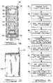
- the specific method used to form the tibial bearing 28 includes several steps which are more fully described below. However, several of these steps involve the use of either a cold isostatic press or a hot isostatic press. Accordingly, the structure and operation of the cold isostatic press and the hot isostatic press will now be described.
- a cold isostatic press 32 which includes a pressure chamber 34 that has an upper cover 36.
- the upper cover 36 includes a threaded closure 38 that enhances a sealed condition within the pressure chamber 34 when the pressure chamber 34 is pressurized.
- the length of the pressure chamber 34 is approximately 24-30 inches and the diameter of the pressure chamber 34 is approximately 12 inches.
- the pressure chamber 34 is substantially surrounded by an annular wall 40 which is operable to define the pressure chamber 34, and has a thickness which is sufficient to contain the pressure within the pressure chamber 34.
- the cold isostatic press 32 further includes a pressure inlet line 42 and a pressure relief line 44.
- the pressure inlet line 42 and pressure relief line 44 are preferably tubular passageways each regulated by a pressure control mechanism (not shown) that are operable to accommodate a pressurized transfer of a gas or liquid fluid from an external source (not shown) into and out of the pressure chamber 34.
- the cold isostatic press 32 is preferably designed to operate at pressures capable of compacting the powder to about 60-80% of its desired final density, with the preferable range being between 65-75%.
- the cold isostatic press 32 may be that which is available from National Forge, Andover, Massachusetts, or Models IP6-24-60 and IP8-36-60 which are available from ABB Autoclave Systems, Inc. of Columbus, Ohio. However, other suitable cold isostatic presses may be used.
- the hot isostatic press 46 will now be described with reference to FIG. 3.
- the hot isostatic press 46 is shown to include a pressure chamber 48 which is defined in part by an annular wall 50, the thickness of which is between about 6 inches and about 3 inches.
- the pressure chamber 48 is about 18 inches in diameter and is about 53 inches in length.
- the hot isostatic press 46 further includes a lower closure 52 and upper closure 54 which are threadedly attached to the annular wall 50 by matching buttress threads 56 and 58. It is to be understood, however, that a pin locking mechanism may also be employed for securing the lower closure 52 and upper closure 54 to the annular wall 50.
- the lower closure 52 and upper closure 54 are operable to maintain a heated and pressurized condition within the pressure chamber 48 during the hot isostatic pressure treatment described below.
- the hot isostatic press 46 further includes a plurality of heating elements 60 that are operable to generate thermal energy within the pressure chamber 48.
- the hot isostatic press 46 may include another heating means, such as a solution jacket adjacent to the pressure chamber 48, that is operable to contain a hot fluid for providing thermal energy to the pressure chamber 48.
- the hot isostatic press 46 is also shown to include a cooling jacket 62 which comprises a plurality of coils encircling the annular wall 50.
- the cooling jacket 62 is operable to contain a suitable heat transfer fluid for removing thermal energy from the hot isostatic press 46 by a transfer of thermal energy into the cooling fluid. It will be understood, however, that the cooling function accomplished by the cooling jacket 62 can be performed by another cooling means disposed at a different location within the hot isostatic press 46, such as within the pressure chamber 48 or between the pressure chamber 48 and the annular wall 50.
- the hot isostatic press 46 further includes a heat shield 64 which is located between the annular wall 50 and the heating elements 60.
- the heat shield 64 is operable to limit heat losses from within the pressure chamber 48 and to assist in controlling the temperature within the pressure chamber 48.
- the hot isostatic press 46 also includes a pressure system (not shown) of a type well-known to those skilled in the art that is operable to pressurize the pressure chamber 48.
- the pressure system also communicates with the pressure chamber 48 by means of a pressure input/output line 68 that is connected to an inert gas source and compressor of a type well-known to those skilled in the art.
- the inert gas is argon, though nitrogen, helium and neon gases may also be used.
- the hot isostatic press 46 further includes a power distribution system (not shown) of a type well-known to those skilled in the art.
- the power distribution system is used for controlling the heat and pressure within the pressure chamber 48.
- the electrical energy required by the heating elements 60 is provided in this embodiment by an electrical power line 72 that is connected to an electrical power source (not shown).
- the hot isostatic press 46 is operable to change the temperature within the pressure chamber 48 from an initial room temperature of from about 60° F to about 70° F to an operating temperature of from about 365° F to about 420° F. In addition, the hot isostatic press 46 is also operable to change the pressure within the pressure chamber 48 from approximately atmospheric pressure to an operating pressure of preferably from about 7,500 pounds per square inch to about 10,000 pounds per square inch.
- the hot isostatic press 46 may be one of several well-known to those skilled in the art, such as Model HP6-30, available from Iso-Spectrum, Inc. of Columbus, Ohio. Other suitable hot isostatic presses are available from National Forge of Andover, Massachusetts. However, other suitable hot isostatic presses may be used.
- an ultra-high molecular weight polyethylene powder is introduced into a first container 98 (see FIG. 3) so as to substantially fill the first container 98.
- the first container 98 is preferably both flexible and collapsible, and is made from a material that has sufficient strength to contain the powder over the operating pressure ranges during the cold isostatic pressure treatment without exhibiting any physical deterioration, chemical degradation or chemical interaction with the powder disposed therein. It is also preferred that the first container 98 be made of a material that will not adhere to the powder at any time during the cold isostatic pressure treatment.
- the first container 98 is a cylindrical polyurethane container of dimensions approximately 6 inches in diameter, 18 inches in length, and has a wall thickness of approximately one-half inch to three-fourths inch.
- the first container 98 is sealed by means of a plug 100 that is inserted into a matching port 102 at one end of the first container 98.
- the plug 100 is secured to the first container 98 by means of an adhesive, such as a hot melt glue, located on the top of the interface of the plug 100 and the matching port 102.
- the plug 100 of the first container 98 preferably includes an evacuation/de-airing tube 104.
- the evacuation/de-airing tube 104 is operable to be connected to an evacuation pump (not shown) and subsequently sealed by any suitable means prior to the cold isostatic pressure treatment.
- the size and shape of the first container 98 will vary depending upon the desired size and shape of the consolidated stock being formed. It will also be noted that other suitable materials may be used to form the first container 98 and that other suitable means may be used for substantially sealing and evacuating the first container 98. For example, a flexible and collapsible rubber material may be employed for constructing the first container 98. When constructed of polyurethane, the first container 98 may be reused provided it is not subjected to extended periods of high temperature.
- the first container 98 is sealed in the manner described above.
- the first container 98 is then substantially evacuated and then the evacuation/de-airing tube 104 is sealed by any suitable means such as by a clamp 106.
- the first container 98 is then located within the pressure chamber 34 of the cold isostatic press 32.
- the pressure chamber 34 is substantially sealed at step 84 to enclose the first container 98 by threading the upper cover 36 onto the matching threads 38 disposed upon the annular wall 40.
- the first container 98 is then subjected to a cold isostatic pressure treatment as indicated by the step 86 during which a uniform pressure is applied to the first container 98.
- the pressure applied to the first container 98 is developed by introducing a pressurized fluid into the pressure chamber 34.
- This pressurized fluid may be water, mineral oil or other oils having similar compressive properties, as well as inert gases such as argon, nitrogen, helium and neon.
- the pressure chamber 34 may be partially filled with water while the pressurized gas may be used to fill the remainder of the pressure chamber 34.
- the pressure within the pressure chamber 34 is preferably increased as quickly as possible from approximately atmospheric pressure to a pressure sufficient to form the powder into an incompletely consolidated stock that can be manipulable for further processing without substantial degradation.
- Suitable maximum pressures range from 1100 psi to 10,000 psi which are generally sufficient to compact the powder to 60-80% of its final density. Below this range the incompletely consolidated stock is structurally unstable and above this range gases may become trapped within the incompletely consolidated stock during evacuation of the first container 98.
- the maximum pressure applied to the first container 98 is approximately 1500 psi, and the typical length of time for increasing the pressure to this level may be approximately 2 to 5 minutes.
- maximum pressure applied to the first container 98 is dependent upon several factors including the size of the first container 98, the amount of powder within the first container 98, the size of the resulting stock needed to manufacture the tibial bearing 28 and the size of the pressure chamber 34. The pressure is preferably held at the maximum pressure for approximately one minute, though longer times can be used.
- the pressure is slowly reduced so as to allow the resulting incompletely consolidated stock to relax within the first container 98 without yielding to outward internal pressure which can cause the incompletely consolidated stock to lose integrity.
- the pressure is preferably released over a period of from approximately 10 to approximately 30 minutes, although longer times can be used.
- the cold isostatic press treatment enhances a uniform density within the incompletely consolidated stock and reduces internal stresses from appearing within the material being formed during the subsequent hot isostatic pressure treatment.
- the shape of the incompletely consolidated stock is in large part dependent upon the shape of the first container 98.
- the incompletely consolidated stock resulting from the cold isostatic press treatment is typically compacted to a preferred density of about 70% of its desired final density following the hot isostatic pressure treatment.
- the second container 108 is preferably a collapsible container made from a material that has sufficient strength to contain the incompletely consolidated stock over the temperature and pressure ranges encountered in the hot isostatic press treatment without exhibiting any physical deterioration, chemical degradation or chemical interaction with the incompletely consolidated stock. It is also preferred that the second container 108 be made of a material that will not adhere to the incompletely consolidated stock at any time during the hot isostatic pressure treatment.
- the second container 108 is a foilized heat sealable bag that has an external surface formed from a layer of an aluminum foil with a polyester vapor barrier, and has an internal surface formed from a heat-sealable, low density polyethylene layer on its internal surface.
- the second container 108 may typically be approximately 18 inches in length, approximately 12 inches in width and have a wall thickness of between approximately 2-3 mils.
- the second container 108 may be made from other suitable materials as well.
- the second container 108 preferably includes an evacuation tube 110 that is operable to be connected to a vacuum pump (not shown).
- the evacuation tube 110 is placed in the second container 108 and then a heat sealer is used to seal that region of the second container 108 which is not immediately adjacent to the evacuation tube 110. Hot melt glue is then placed around the region of the second container 108 which is adjacent to the evacuation tube 110.
- the size and shape of the second container 108 will vary depending upon the desired size and shape of the consolidated stock being formed. It will also be noted that other suitable materials may be used for the second container 108 and that other suitable means may be used for sealing and evacuating the second container 108.
- the second container 108 is evacuated in similar fashion to the evacuation of the first container 98 as indicated by the step 90.
- a heat sealer is then used to substantially enclose the second container 108 at a region below the evacuation tube 110.
- the evacuation tube 110 may then be removed from the second container 108.
- the second container 108 is then placed into the pressure chamber 48 of the hot isostatic press 46 as indicated by the step 92 of the present invention.
- the lower closure 52 and the upper closure 54 of the hot isostatic press 46 are then closed to substantially enclose the second container 108 within the hot isostatic press 46.
- the incompletely consolidated stock undergoes the hot isostatic pressure treatment.
- the pressure within the pressure chamber 48 is initially raised to approximately 24 psi while the temperature of the hot isostatic press 46 is raised between 365°F and 420°F. Below this range the incompletely . consolidate stock does not melt and above this range the polyethylene may degrade.
- the temperature of the hot isostatic press is raised to between 365° - 385°F to minimize the possibility that degradation will occur. Most preferably, the temperature is raised to 365°F. Once 365°C is reached, the temperature of the hot isostatic press 46 is raised as quickly as possible and may typically heat between one to three hours.
- the pressure, within the pressure vessel 46 is also increased over a 1-2 hours period to a pressure preferably between about 7,500 to about 10,000 psi.
- the maximum pressure may range from about 3,000 psi to about 40,000 psi.
- pressures below 3,000 psi or above 40,000 psi tend to cause consolidation errors to occur or may cause the resulting completely consolidated stock to have an undesirable crystalline structure.
- the preferred maximum pressure between 7,500 psi and 10,000 psi is dependent upon several factors including the size, shape and construction of the second container, the dimensions of the pressure chamber 48 and the desired final diameter of the resulting completely consolidated stock.
- the duration of the hot isostatic pressure treatment may also depend on the size of the resulting completely consolidated stock. For example, smaller diameters of the completely consolidated stock (e.g., 1-1/2 inches) typically require less time to become fully compacted, while larger diameters of completely consolidated stock, such as 4 inches, typically require more time to become fully cured. In addition, the use of the lowest satisfactory pressure is desirable as it would tend to prolong equipment life.
- An inert gas such as argon is preferably used in the hot isostatic press 46 as the pressure medium.
- Alternative selections for the pressure medium include nitrogen, helium and neon gases, although these gases can be chemically reactive under certain conditions.
- dwell times are dependent upon the desired final diameter of the consolidated stock being produced, and range from approximately 45 minutes to several hours or more. For example, typical desired dwell times may be approximately 45 minutes to approximately 1 hour for a 1 inch diameter consolidated stock, approximately 2 hours for a 2-1/2 inch diameter consolidated stock, and approximately 5 hours for a 4 inch diameter consolidated stock.
- the hot isostatic press 46 is allowed to cool to room temperature. After the temperature of the hot isostatic press 46 cools to approximately 100°F, the pressure within the pressure chamber 48 is gradually decreased to approximately atmospheric pressure over a period of time that is dependent upon the desired final diameter of the consolidated stock being produced. In this regard, the pressure for larger diameters of consolidated stock may be reduced more slowly because they may typically have a larger internal compression and larger potential energy that are more likely to release upon removal of pressure. For example, a 1 hour pressure release time is preferred for a 4 inch diameter consolidated stock, while a 20 minute pressure release time may be sufficient for a 1-1/2 inch diameter consolidated stock. After the release time has elapsed, the pressure chamber 48 is then opened and the second container 108 is removed from the pressure chamber 48.
- the consolidated stock is removed from the second container 108 and is machined at step 96 under methods well-known to those skilled in the art to produce the desired product, such as the tibial bearing 28, acetabular cup replacement or other biocompatible component.
- the tibial bearing 28 is then sterilized in a manner well-known to those skilled in the art.
- the hot isostatic press 46 may be also used to enhance the adhesion between materials which form a composite biocompatible component.
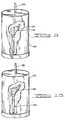
- a biocompatible component 112 representing a femoral hip stem of a hip joint prosthesis is shown.
- the biocompatible component 112 is preferably formed of a biocompatible thermoplastic having a biocompatible fibrous material disposed therein.
- the biocompatible thermoplastic may be polysulfone, poly ether ether ketone (PEEK), or poly aryl ether ketone (PAEK), though other suitable materials may be used.
- the amount and orientation of the biocompatible fibrous material within the biocompatible component 112 is selected to achieve the desired structural modulus for the biocompatible component.
- the biocompatible fibrous material may be either continuous or chopped fibers, though other suitable materials may be used.
- a sheet of the biocompatible thermoplastic such as polysulfone is first formed into two portions, each portion having a shape generally corresponding to one-half of the biocompatible component 112. Each portion of the biocompatible thermoplastic is then placed within the container 114 with the biocompatible fibrous material disposed between the portions.
- the container 114 is preferably made from copper or stainless steel. However, other suitable materials such as high temperature silicon, which does adhere to the polysulfone, may also be used.
- the container 114 is then filled with zirconium oxide beads (i.e., Zr 2 O 3 ) and is then evacuated using the evacuation tube 115 which is then sealed.
- zirconium oxide beads do not have to be used when the container 114 is made from a very pliable material such as high temperature silicon.
- the container 114 is then placed in the hot isostatic press 46 and is subjected to the hot isostatic pressure treatment in a manner similar to that described above.
- the maximum temperature of the isostatic pressure treatment is preferably slightly above the melting temperature of the biocompatible thermoplastic.
- the pressure applied and the duration of the hot isostatic pressure treatment should be sufficient to cause the biocompatible thermoplastic to encapsulate the biocompatible fibrous material.
- the temperature will fall within the range of 400 - 440°F while the pressure will be greater than between 5000 psi and 7500 psi, and most preferably greater than 7500 psi. It will be understood by those skilled in the art, however, that the temperature, pressure and duration of the hot isostatic pressure treatment will depend upon the specific materials being used.
- the isostatic press 46 may also be used to reduce the voids in a stock of biocompatible composite material prior to being machined into a biocompatible component.
- a biocompatible material stock 116 is shown as being disposed within a container 118.
- the biocompatible material stock 116 may be made from polysulfone, poly ether ether ketone (PEEK), or poly arly ether ketone (PAEK), though other suitable materials may be used.
- the container 118 may be a stainless steel or a copper container. However, the container may also be a stainless steel heat treat bag of the type which is available from Sentry Company, Foxboro, Massachusetts, other suitable containers may be used.
- the biocompatible material stock 116 is first placed within the container 118 and then the container 118 is filled with zirconium oxide beads. It will be appreciated, however, that zirconium oxide beads do not have to be used if the container 118 is made from a pliable material such as a heat treat bag.
- the container 118 is then sealed. A vacuum is then drawn on the container 118 through the evacuation tube 119 and then the evacuation tube 119 is then sealed by closing a valve connected to the evacuation tube 119.
- the container 118, with the biocompatible stock material 116 located therein, is placed in the isostatic press 46 and the temperature and pressure of the isostatic press 46 are raised to such an extent that the voids formed within the biocompatible stock material 116 are reduced.
- the temperature to which the hot isostatic press 46 is raised will be substantially that of the glass transition temperature of the resin of the biocompatible stock material 116, while the pressure applied by the hot isostatic press 46 is as high as reasonably possible.
- the temperature will fall within the range of 400 - 440°F while the pressure will be greater than between 5000 psi and 7500 psi, and most preferably greater than 7500 psi.
- other suitable temperatures and pressures may be used.
- the isostatic press 46 may also be used to enhance the adhesion of a porous coating on a biocompatible component formed from a composite material.
- the biocompatible component 120 includes a porous coated surface 122 which is used to facilitate adhesion of the biocompatible component immediately after surgery.
- the porous coated surface 122 may be applied by a plasma spray operation and may comprise an alloy of Ti-6Al-4V, commercially pure titanium, a cobalt chrome alloy or other biocompatible materials.
- the porous coated surface 122 is first applied to the biocompatible component 120 by a plasma spray operation.
- the biocompatible component 120 is then placed in a container 124 and then the container 124 is filled with zirconium oxide beads.
- the container 124 is then sealed and then is evacuated through the evacuation tube 125.
- the container 124 is preferably made of stainless steel or copper. However, other suitable materials such as high temperature silicon, which does not adhere to the component 120 may also be used. It will be appreciated, however, that zirconium oxide beads do not have to be used if the container 124 is made from a pliable material such as high temperature silicon.
- the container 124, with the biocompatible component 120 inside, is then placed in a hot isostatic press 46 which is then operated in a manner similar to that described above.
- the temperature will fall within the range of 400 - 440°F while the pressure will be greater than between 5000 psi and 7500 psi, and most preferably greater than 7500 psi.
- the adhesion of the porous coated surface 122 to the biocompatible component 120 is improved.
- the hot isostatic press 46 may also be used to enhance adhesion of porous coated pads on a biocompatible component.
- the biocompatible component 126 includes a plurality of porous coated pads 128 which are used to facilitate fixation of the biocompatible component 126 immediately after surgery.
- the porous coated pads 128 may be made from a titanium alloy such as Ti-6Al-4V, commercially pure titanium, a cobalt chrome alloy or other biocompatible metal alloys. While the porous coating on the porous coated pads 128 may be applied by a flame spray, plasma spray or sputtering techniques, it will be appreciated that other suitable methods may be used.
- the regions on the biocompatible component 126 where the porous coated pads 128 are to be placed are first coated with methylene chloride to partially dissolve those regions at the biocompatible component 126.
- the porous coated pads 128 are then applied to the biocompatible component 126 and are temporarily secured thereto.
- the biocompatible component 126, together with the porous coated pads 128, are then placed in the container 130 and then the container 130 is filled with zirconium oxide beads.
- the container may be made from stainless steel or copper, though other suitable materials may be used.
- pliable materials such as high temperature silicon which is able to withstand the operating temperatures and pressures may be used which do not necessarily require the use of zirconium oxide beads.
- the container 130 is placed in the hot isostatic press 46 which is then operated in a manner similar to that described above.
- the temperature will fall within the range of 400 - 440°F while the pressure will be greater than between 5000 psi and 7500 psi, and most preferably greater than 7500 psi.
- the porous coated pads 128 are relatively securely attached to the biocompatible component 126.
- Polyethylene powder having a molecular weight of approximately 3 million and conforming to ASTM F 648-84 is introduced into a first container formed from polyurethane of approximately 6 inches in diameter, 18 inches in length, and of approximately one-half inch wall thickness.
- the first container is substantially sealed and substantially evacuated, and is then placed in the cold isostatic press 32.
- the cold isostatic press is then closed, and the pressure therein is increased by introducing pressurized water into the pressure vessel to approximately 1500 psi over approximately a 2 minute period.
- the pressure is then maintained within the cold isostatic press for approximately 1 minute, and is then decreased to atmospheric pressure over approximately a 10 minute period.
- the cold isostatic press is then opened and the first container is removed and opened to reveal a cylindrical incompletely consolidated stock of dimensions 5-1/2 inches in diameter and 14 inches in length.
- the incompletely consolidated stock is then placed in a second container.
- the second container is formed from an aluminum foil layer with a polyester vapor barrier on its external surface and a heat-sealable, low density polyethylene layer on its internal surface.
- the second container is approximately 18 inches in length, 12 inches in width and has a wall thickness of 2-3 mils.
- the second container is then evacuated and sealed.
- the second container is then placed in the hot isostatic press and then the hot isostatic press is closed.
- the temperature of the hot isostatic press is then increased from room temperature to 400°F over approximately a 1 hour period.
- pressurized argon gas is introduced into the pressure chamber of the hot isostatic press to increase the internal pressure from atmospheric pressure to 10,000 pounds per square inch over approximately a 3 hour period.
- the temperature.and pressure within the hot isostatic press are maintained for approximately 5 hours. The temperature is then allowed to decrease to 100°F over approximately a 4 hour period. At the same time, the pressure within the hot isostatic press is decreased to atmospheric pressure over a 30 minute period.
- the hot isostatic press is opened and the second container is removed. The second container is then opened to reveal a relatively completely consolidated stock which resembles a cylinder having dimensions of 4 inches in diameter and 12 inches in length. The relatively completely consolidated stock is tested to have a crystallinity of 45%-60%. The consolidated stock is subsequently machined to form a tibial bearing which is then packaged and then exposed 2.5 megarads of radiation from a cobalt source for sterilization.
- Two portions of polysulfone approximately 5 mils in thickness are vacuum formed into a shape which resembles each half of a biocompatible component in the form of a hip joint prosthesis described above.
- Each portion of the polysulfone representing the halves of the biocompatible component is then placed in a stainless steel container with continuous carbon fibers disposed between the portions.
- the container is placed in the hot isostatic press and then the hot isostatic press is closed.
- the temperature of the hot isostatic press is then increased from room temperature to approximately 410° F. over approximately a one hour period.
- pressurized argon gas is introduced into the pressure chamber of the hot isostatic press to increase the internal pressure from atmospheric pressure to 7500 psi over approximately a three-hour period.
- the temperature and pressure within the hot isostatic press are maintained for approximately a thirty minute period. The temperature is then allowed to decrease to room temperature after which the pressure is released. After the pressure has been released and the hot isostatic press has been cooled to room temperature, the hot isostatic press is opened and the container is removed. The container is then opened to reveal a biocompatible component in which the polysulfone has encapsulated the carbon fibers.
- a biocompatible component in the form of a hip joint prosthesis described above is initially formed from continuous carbon fibers which are encapsulated by polysulfone. Methylene chloride is applied to the upper portion of the biocompatible component so as to partially dissolve the polysulfone. After portions of the polysulfone have been melted, a plurality of porous coated pads described above are applied to the region of the biocompatible component to which methylene chloride is applied. The biocompatible component with the porous coated pads attached is then placed in a stainless steel container of the type described above which is then filled with zirconium oxide beads. After the container is evacuated and sealed, the container is placed in a hot isostatic press and then the hot isostatic press is closed.
- the temperature of the hot isostatic press is then increased from room temperature to approximately 410°F over approximately a one hour period.
- pressurized argon gas is introduced into the pressure chamber of the hot isostatic press to increase the internal pressure from atmospheric pressure to 5000 psi over an approximately a one hour period.
- the temperature in the pressure of hot isostatic press are maintained for approximately 45 minutes.
- the pressure is then allowed to decrease over approximately a four-hour period, while the temperature within the hot isostatic press is decreased to ambient over a thirty minute period.
- the hot isostatic press is open and the container is removed. The second container is then opened to reveal the biocompatible component with the porous coated pads relatively securely attached.
- a biocompatible material stock in the form of a slab is placed within a stainless steel container which is then formed with zirconium oxide beads.
- the slab is approximately 1.5 inches thick and is 10 in length and 10 in width.
- the container together with the biocompatible material stock is placed in a hot isostatic press.
- the temperature of the hot isostatic press is then increased from room temperature to approximately 430°F over approximately a .75 hour time period.
- pressurized argon gas is introduced into the hot isostatic press to increase the internal pressure from atmospheric to approximately 7500 psi over approximately a one hour time period.
- the temperature and pressure of the isostatic press are maintained for approximately .75 hours.
- the temperature is then reduced to room temperature after which the pressure is released.
- the hot isostatic press is opened and the container is removed. The container is then opened to reveal a slab of biocompatible material stock in which the voids are reduced.
- a biocompatible component in the form of a stem of a hip joint prosthesis described above is initially formed from carbon fibers which are encapsulated by a polysulfone.
- the biocompatible component is then ultrasonic cleaned in water to remove surface containments.
- the biocompatible component is then subjected to a grit blasting operation.
- the portions of the biocompatible component which are not to receive the porous coating are initially covered with polyvinyl chloride tape.
- the biocompatible component is then placed in front of grit blaster operating at 40 psi with a 1/2 inch nozzle using a 16 grit silicon carbide particles. By grit blasting the biocompatible component, a roughen surface is formed in the region which is exposed to the particles.
- the polyvinyl chloride tape is then removed from the biocompatible component.
- a 1/16" drill bit may be used to form the roughened surface.
- the drill bit may be randomly disposed against the portion of the biocompatible component where the roughened surface is to be formed thereby generating a plurality of holes. This process is continued until the desired surface roughness is obtained.
- a dove-tail cutter may also be used to form the roughened surface.
- a dove-tail cutter having a cutting surface of a maximum of 1/32" in diameter may be disposed against the surface of the biocompatible component which is to be roughened and then the axis of rotation of the cutter is moved in a circular fashion. The dove-tail cutter is then removed from the biocompatible component and then disposed against another portion of the surface of the biocompatible component. This process is repeated until the desired surface roughness is obtained.
- the biocompatible component is then cleaned in a second ultrasonic cleaning operation.
- the portions of the biocompatible component which are not to receive the porous coating are then covered with heat tape which is resistant to the high temperature which are to be generated during the plasma spray operation. Care is taken so that the portions of the biocompatible component which are covered by the porous coating are not physically contacted after the second ultrasonic cleaning operation until the porous coating is applied.
- the storage rack which is used to transport the biocompatible component to the plasma spray chamber supports the biocompatible component only at those areas which are not to be coated with porous coating.
- the biocompatible component is then placed in a plasma spray chamber in such a manner that portions of the biocompatible component which receives the porous coating is not touched.
- the spray chamber is initially evacuated to approximately 10 millitorr and then backfilled with argon gas to a pressure slightly above atmospheric.
- the plasma spray is then applied to the biocompatible component for a period of approximately 20 seconds.
- the biocompatible component is placed in front of the exhaust fan of the spray chamber for approximately 1 minute. This process of applying the plasma spray and then cooling the biocompatible component is repeated approximately 8 times.
- the biocompatible component is then removed from the spray chamber and then sandpaper is used to remove loose material from the biocompatible component.
- the biocompatible component is washed in a water jet operating at 900 psi to remove additional residue.
- the biocompatible component is then placed in a stainless steel container of the type described above which is then filled with zirconium oxide beads.
- the container is then evacuated and sealed.
- the container, together with the biocompatible component, is then placed in a hot isostatic press and then the hot isostatic press is closed.
- the temperature of the hot isostatic press is then increased from room temperature to approximately 430°F and while the pressure is increased to 7500 psi.
- the temperature and pressure of the hot isostatic press are maintained for approximately 45 minutes.
- the temperature of the hot isostatic press is then allowed to cool to approximately 100°F over a one hour time period and then the pressure of the hot isostatic press is decreased to atmospheric over a thirty-minute time period.
- the hot isostatic press is then cooled to room temperature after which the hot isostatic press and the container is removed.
- the container is then opened to reveal a biocompatible component with the porous coated surface relatively securely attached.
- a preheating step may be used to preheat the incompletely consolidated stock prior to placing the consolidated stock in the hot isostatic press.
- the various containers may be of different sizes and of different materials.
- filters such as paper towels may be located within the various evacuation tubes.
Landscapes
- Engineering & Computer Science (AREA)
- Mechanical Engineering (AREA)
- Health & Medical Sciences (AREA)
- Chemical & Material Sciences (AREA)
- Public Health (AREA)
- Veterinary Medicine (AREA)
- Oral & Maxillofacial Surgery (AREA)
- Transplantation (AREA)
- Biomedical Technology (AREA)
- Heart & Thoracic Surgery (AREA)
- Vascular Medicine (AREA)
- Life Sciences & Earth Sciences (AREA)
- Animal Behavior & Ethology (AREA)
- General Health & Medical Sciences (AREA)
- Orthopedic Medicine & Surgery (AREA)
- Cardiology (AREA)
- Manufacturing & Machinery (AREA)
- Physics & Mathematics (AREA)
- Materials Engineering (AREA)
- Composite Materials (AREA)
- Fluid Mechanics (AREA)
- Plasma & Fusion (AREA)
- Chemical Kinetics & Catalysis (AREA)
- Metallurgy (AREA)
- Organic Chemistry (AREA)
- Materials For Medical Uses (AREA)
- Prostheses (AREA)
- Casting Or Compression Moulding Of Plastics Or The Like (AREA)
Applications Claiming Priority (3)
| Application Number | Priority Date | Filing Date | Title |
|---|---|---|---|
| US08/006,747 US5466530A (en) | 1993-01-21 | 1993-01-21 | Biocompatible components fabricated from a substantially consolidated stock of material |
| EP19940907414 EP0680290B1 (de) | 1993-01-21 | 1994-01-21 | Verfahren zum formen von biokompatiblen komponenten |
| US6747 | 1998-01-13 |
Related Parent Applications (1)
| Application Number | Title | Priority Date | Filing Date |
|---|---|---|---|
| EP19940907414 Division EP0680290B1 (de) | 1993-01-21 | 1994-01-21 | Verfahren zum formen von biokompatiblen komponenten |
Publications (3)
| Publication Number | Publication Date |
|---|---|
| EP1166926A2 true EP1166926A2 (de) | 2002-01-02 |
| EP1166926A3 EP1166926A3 (de) | 2002-05-22 |
| EP1166926B1 EP1166926B1 (de) | 2005-08-17 |
Family
ID=21722374
Family Applications (1)
| Application Number | Title | Priority Date | Filing Date |
|---|---|---|---|
| EP01122088A Expired - Lifetime EP1166926B1 (de) | 1993-01-21 | 1994-01-21 | Verfahren zum Formen von biokompatiblen Komponenten |
Country Status (4)
| Country | Link |
|---|---|
| EP (1) | EP1166926B1 (de) |
| JP (1) | JP2004106557A (de) |
| AT (1) | ATE219980T1 (de) |
| DE (2) | DE69434464T2 (de) |
Cited By (1)
| Publication number | Priority date | Publication date | Assignee | Title |
|---|---|---|---|---|
| CN117140901A (zh) * | 2023-10-19 | 2023-12-01 | 宁津县华泰高耐磨工程塑料有限公司 | 一种陶瓷填料的超高分子量聚乙烯复合棒材及加工装置 |
Families Citing this family (1)
| Publication number | Priority date | Publication date | Assignee | Title |
|---|---|---|---|---|
| CN115966709A (zh) * | 2021-10-09 | 2023-04-14 | 罗伯特·博世有限公司 | 用于燃料电池的双极板及其制备方法 |
Family Cites Families (11)
| Publication number | Priority date | Publication date | Assignee | Title |
|---|---|---|---|---|
| US4187210A (en) * | 1973-12-14 | 1980-02-05 | E. I. Du Pont De Nemours And Company | Homogeneous, highly-filled, polyolefin composites |
| US4644942A (en) * | 1981-07-27 | 1987-02-24 | Battelle Development Corporation | Production of porous coating on a prosthesis |
| US4619792A (en) * | 1983-06-03 | 1986-10-28 | Raytheon Company | Process for making an optically transmissive body |
| US5201766A (en) * | 1985-09-11 | 1993-04-13 | Smith & Nephew Richards Inc. | Prosthetic device with porous matrix and method of manufacture |
| US4744943A (en) * | 1986-12-08 | 1988-05-17 | The Dow Chemical Company | Process for the densification of material preforms |
| US4854496A (en) * | 1987-01-16 | 1989-08-08 | Dynamet, Inc. | Porous metal coated implant and method for producing same |
| CA2005002C (en) * | 1988-12-20 | 2003-01-28 | William M. Goldberger | Improved method for electroconsolidation of a preformed particulate workpiece |
| US5051218A (en) * | 1989-02-10 | 1991-09-24 | The Regents Of The University Of California | Method for localized heating and isostatically pressing of glass encapsulated materials |
| US5030402A (en) * | 1989-03-17 | 1991-07-09 | Zachariades Anagnostis E | Process for producing a new class of ultra-high-molecular-weight polyethylene orthopaedic prostheses with enhanced mechanical properties |
| US5037928A (en) * | 1989-10-24 | 1991-08-06 | E. I. Du Pont De Nemours And Company | Process of manufacturing ultrahigh molecular weight linear polyethylene shaped articles |
| US5066454A (en) * | 1990-06-20 | 1991-11-19 | Industrial Materials Technology, Inc. | Isostatic processing with shrouded melt-away mandrel |
-
1994
- 1994-01-21 AT AT94907414T patent/ATE219980T1/de active
- 1994-01-21 DE DE69434464T patent/DE69434464T2/de not_active Expired - Lifetime
- 1994-01-21 DE DE69430900T patent/DE69430900T2/de not_active Expired - Lifetime
- 1994-01-21 EP EP01122088A patent/EP1166926B1/de not_active Expired - Lifetime
-
2003
- 2003-12-03 JP JP2003405076A patent/JP2004106557A/ja not_active Withdrawn
Cited By (1)
| Publication number | Priority date | Publication date | Assignee | Title |
|---|---|---|---|---|
| CN117140901A (zh) * | 2023-10-19 | 2023-12-01 | 宁津县华泰高耐磨工程塑料有限公司 | 一种陶瓷填料的超高分子量聚乙烯复合棒材及加工装置 |
Also Published As
| Publication number | Publication date |
|---|---|
| EP1166926B1 (de) | 2005-08-17 |
| ATE219980T1 (de) | 2002-07-15 |
| DE69434464T2 (de) | 2006-07-13 |
| JP2004106557A (ja) | 2004-04-08 |
| DE69434464D1 (de) | 2005-09-22 |
| DE69430900D1 (de) | 2002-08-08 |
| DE69430900T2 (de) | 2002-11-14 |
| EP1166926A3 (de) | 2002-05-22 |
Similar Documents
| Publication | Publication Date | Title |
|---|---|---|
| US5505984A (en) | Method for forming biocompatible components using an isostatic press | |
| US5830396A (en) | Method for processing thermoplastics, thermosets and elastomers | |
| EP1421918B1 (de) | Prothesenvorrichtung und Verfahren zur Herstellung derselben | |
| US20080178998A1 (en) | Crosslinked polymeric composite for orthopaedic implants | |
| US5807407A (en) | Medical implant device and method for making same | |
| CA2313928C (en) | Method of manufacturing an articulating bearing surface for an orthopaedic implant | |
| EP0681845B1 (de) | Verbund-Polymer-Implantat und Verfahren zur Herstellung desselben | |
| US5201766A (en) | Prosthetic device with porous matrix and method of manufacture | |
| RU2211008C2 (ru) | Протезные устройства из полиэтилена сверхвысокой молекулярной массы, обработанного облучением и плавлением | |
| EP1676548B1 (de) | Verfahren zur Herstellung eines orthopädischen Trägerteils | |
| CA2419326C (en) | Method of making an orthopaedic implant having a porous metal surface | |
| CA2311631C (en) | Net shaped and crosslinked articulating bearing surface for an orthopaedic implant | |
| US4854496A (en) | Porous metal coated implant and method for producing same | |
| EP0562038B1 (de) | Verfahren zum herstellen von fortschrittlichen verbundkonstruktionen und hergestellte produkte | |
| EP0963824B1 (de) | Verfahren zur Herstellung vernetzter, geformter Kunststofflager | |
| EP1166926B1 (de) | Verfahren zum Formen von biokompatiblen Komponenten | |
| JP4752039B2 (ja) | 放射線および溶解処理済み超高分子量ポリエチレンプロテーゼおよびそれを用いた医療用物品 | |
| JP5073626B2 (ja) | 放射線および溶融処理済み超高分子量ポリエチレンプロテーゼデバイス | |
| EP1413414B1 (de) | Verfahren zur Herstellung vernetzter geformter Kunststofflager | |
| CA2615068C (en) | Radiation and melt treated ultra high molecular weight polyethylene prosthetic devices | |
| KR20260066658A (ko) | 보철용 임플란트 제조 방법 및 그에 의해 얻어진 보철용 임플란트 | |
| JPH03253503A (ja) | 導電物質の高密度焼結方法 |
Legal Events
| Date | Code | Title | Description |
|---|---|---|---|
| PUAI | Public reference made under article 153(3) epc to a published international application that has entered the european phase |
Free format text: ORIGINAL CODE: 0009012 |
|
| 17P | Request for examination filed |
Effective date: 20010914 |
|
| AC | Divisional application: reference to earlier application |
Ref document number: 680290 Country of ref document: EP |
|
| AK | Designated contracting states |
Kind code of ref document: A2 Designated state(s): AT BE CH DE DK ES FR GB GR IE IT LI LU MC NL PT SE |
|
| PUAL | Search report despatched |
Free format text: ORIGINAL CODE: 0009013 |
|
| RIN1 | Information on inventor provided before grant (corrected) |
Inventor name: ENGLAND, GARRY LEE Inventor name: HIGGINS, JOEL C. |
|
| AKX | Designation fees paid |
Designated state(s): CH DE FR GB LI SE |
|
| 17Q | First examination report despatched |
Effective date: 20030512 |
|
| GRAP | Despatch of communication of intention to grant a patent |
Free format text: ORIGINAL CODE: EPIDOSNIGR1 |
|
| GRAS | Grant fee paid |
Free format text: ORIGINAL CODE: EPIDOSNIGR3 |
|
| GRAA | (expected) grant |
Free format text: ORIGINAL CODE: 0009210 |
|
| AC | Divisional application: reference to earlier application |
Ref document number: 0680290 Country of ref document: EP Kind code of ref document: P |
|
| AK | Designated contracting states |
Kind code of ref document: B1 Designated state(s): CH DE FR GB LI SE |
|
| REG | Reference to a national code |
Ref country code: GB Ref legal event code: FG4D |
|
| REG | Reference to a national code |
Ref country code: CH Ref legal event code: EP |
|
| REF | Corresponds to: |
Ref document number: 69434464 Country of ref document: DE Date of ref document: 20050922 Kind code of ref document: P |
|
| REG | Reference to a national code |
Ref country code: CH Ref legal event code: NV Representative=s name: R. A. EGLI & CO. PATENTANWAELTE |
|
| REG | Reference to a national code |
Ref country code: SE Ref legal event code: TRGR |
|
| ET | Fr: translation filed | ||
| PLBE | No opposition filed within time limit |
Free format text: ORIGINAL CODE: 0009261 |
|
| STAA | Information on the status of an ep patent application or granted ep patent |
Free format text: STATUS: NO OPPOSITION FILED WITHIN TIME LIMIT |
|
| 26N | No opposition filed |
Effective date: 20060518 |
|
| PGFP | Annual fee paid to national office [announced via postgrant information from national office to epo] |
Ref country code: SE Payment date: 20130129 Year of fee payment: 20 Ref country code: GB Payment date: 20130125 Year of fee payment: 20 Ref country code: DE Payment date: 20130129 Year of fee payment: 20 Ref country code: FR Payment date: 20130211 Year of fee payment: 20 Ref country code: CH Payment date: 20130125 Year of fee payment: 20 |
|
| REG | Reference to a national code |
Ref country code: DE Ref legal event code: R071 Ref document number: 69434464 Country of ref document: DE |
|
| REG | Reference to a national code |
Ref country code: CH Ref legal event code: PL |
|
| REG | Reference to a national code |
Ref country code: GB Ref legal event code: PE20 Expiry date: 20140120 |
|
| REG | Reference to a national code |
Ref country code: SE Ref legal event code: EUG |
|
| PG25 | Lapsed in a contracting state [announced via postgrant information from national office to epo] |
Ref country code: DE Free format text: LAPSE BECAUSE OF EXPIRATION OF PROTECTION Effective date: 20140122 Ref country code: GB Free format text: LAPSE BECAUSE OF EXPIRATION OF PROTECTION Effective date: 20140120 |