EP1166932A1 - Spindel in einer Werkzeugmaschine - Google Patents
Spindel in einer Werkzeugmaschine Download PDFInfo
- Publication number
- EP1166932A1 EP1166932A1 EP01113246A EP01113246A EP1166932A1 EP 1166932 A1 EP1166932 A1 EP 1166932A1 EP 01113246 A EP01113246 A EP 01113246A EP 01113246 A EP01113246 A EP 01113246A EP 1166932 A1 EP1166932 A1 EP 1166932A1
- Authority
- EP
- European Patent Office
- Prior art keywords
- spindle according
- crown
- spindle
- guide
- segments
- Prior art date
- Legal status (The legal status is an assumption and is not a legal conclusion. Google has not performed a legal analysis and makes no representation as to the accuracy of the status listed.)
- Granted
Links
Images


Classifications
-
- B—PERFORMING OPERATIONS; TRANSPORTING
- B23—MACHINE TOOLS; METAL-WORKING NOT OTHERWISE PROVIDED FOR
- B23B—TURNING; BORING
- B23B31/00—Chucks; Expansion mandrels; Adaptations thereof for remote control
- B23B31/02—Chucks
- B23B31/24—Chucks characterised by features relating primarily to remote control of the gripping means
- B23B31/26—Chucks characterised by features relating primarily to remote control of the gripping means using mechanical transmission through the working-spindle
- B23B31/261—Chucks characterised by features relating primarily to remote control of the gripping means using mechanical transmission through the working-spindle clamping the end of the toolholder shank
- B23B31/265—Chucks characterised by features relating primarily to remote control of the gripping means using mechanical transmission through the working-spindle clamping the end of the toolholder shank by means of collets
-
- Y—GENERAL TAGGING OF NEW TECHNOLOGICAL DEVELOPMENTS; GENERAL TAGGING OF CROSS-SECTIONAL TECHNOLOGIES SPANNING OVER SEVERAL SECTIONS OF THE IPC; TECHNICAL SUBJECTS COVERED BY FORMER USPC CROSS-REFERENCE ART COLLECTIONS [XRACs] AND DIGESTS
- Y10—TECHNICAL SUBJECTS COVERED BY FORMER USPC
- Y10T—TECHNICAL SUBJECTS COVERED BY FORMER US CLASSIFICATION
- Y10T408/00—Cutting by use of rotating axially moving tool
- Y10T408/94—Tool-support
- Y10T408/95—Tool-support with tool-retaining means
- Y10T408/953—Clamping jaws
-
- Y—GENERAL TAGGING OF NEW TECHNOLOGICAL DEVELOPMENTS; GENERAL TAGGING OF CROSS-SECTIONAL TECHNOLOGIES SPANNING OVER SEVERAL SECTIONS OF THE IPC; TECHNICAL SUBJECTS COVERED BY FORMER USPC CROSS-REFERENCE ART COLLECTIONS [XRACs] AND DIGESTS
- Y10—TECHNICAL SUBJECTS COVERED BY FORMER USPC
- Y10T—TECHNICAL SUBJECTS COVERED BY FORMER US CLASSIFICATION
- Y10T409/00—Gear cutting, milling, or planing
- Y10T409/30—Milling
- Y10T409/309352—Cutter spindle or spindle support
- Y10T409/309408—Cutter spindle or spindle support with cutter holder
- Y10T409/309464—Cutter spindle or spindle support with cutter holder and draw bar
-
- Y—GENERAL TAGGING OF NEW TECHNOLOGICAL DEVELOPMENTS; GENERAL TAGGING OF CROSS-SECTIONAL TECHNOLOGIES SPANNING OVER SEVERAL SECTIONS OF THE IPC; TECHNICAL SUBJECTS COVERED BY FORMER USPC CROSS-REFERENCE ART COLLECTIONS [XRACs] AND DIGESTS
- Y10—TECHNICAL SUBJECTS COVERED BY FORMER USPC
- Y10T—TECHNICAL SUBJECTS COVERED BY FORMER US CLASSIFICATION
- Y10T82/00—Turning
- Y10T82/25—Lathe
- Y10T82/2552—Headstock
- Y10T82/2562—Spindle and bearings
-
- Y—GENERAL TAGGING OF NEW TECHNOLOGICAL DEVELOPMENTS; GENERAL TAGGING OF CROSS-SECTIONAL TECHNOLOGIES SPANNING OVER SEVERAL SECTIONS OF THE IPC; TECHNICAL SUBJECTS COVERED BY FORMER USPC CROSS-REFERENCE ART COLLECTIONS [XRACs] AND DIGESTS
- Y10—TECHNICAL SUBJECTS COVERED BY FORMER USPC
- Y10T—TECHNICAL SUBJECTS COVERED BY FORMER US CLASSIFICATION
- Y10T82/00—Turning
- Y10T82/25—Lathe
- Y10T82/2585—Tool rest
- Y10T82/2589—Quick release tool or holder clamp
Definitions
- the invention relates to a spindle in a machine tool with an axis, with a receptacle lying in the axis for a shaft of a tool holder and with a clamping mechanism for axially fixing the shaft in the receptacle, wherein the clamping mechanism has an axially displaceable mandrel as well at least one arranged on a circumference of the mandrel Segment contains that with axial displacement of the mandrel by means of one acting between the mandrel and the segments first guide between a first and a second radial Operating position is axially movable and in the first Operating position, the shaft is positively fixed in the holder.
- a spindle with such a clamping mechanism is known for example from machining centers of the "FZ" type series Applicant.
- the tool holder is included its outer cone in a complementary inner conical receptacle of the spindle head.
- a mandrel of the clamping mechanism then dips into a corresponding receptacle in the shaft of the Tool holder.
- the mandrel is arranged axially Drawbar axially movable.
- the mandrel is in an advanced position Operating position.
- On the outer circumference of the mandrel are over the Several segments arranged around the circumference. The segments are running at the front end into a thickened head that turns into this operating position is located radially inside.
- the invention is based on the object, a To further develop the spindle of the type mentioned at the beginning that the above problems are avoided.
- the spindle of the type mentioned at the beginning is intended to securely engage the tool holder in the Spindle reached and there should be damage to the elements of the tensioning mechanism can be avoided.
- This task is the spindle of the type mentioned solved according to the invention in that a second guide is provided is by means of which the at least one segment in the second Operating position and in any intermediate position between the first and the second operating position kept defined becomes.
- the second tour ensures that all segments are always in a defined position, including and straight in the two operating positions, the radial end positions correspond. In this way it is ensured that a new tool holder always under defined conditions can be inserted with its shaft into the spindle can and there after a short search of the spindle holder with the Coupling speed also the positive connection between Sliding block and groove is made so that the tool holder is not only clamped in the correct angular position but also a reliable non-positive connection in the area of the conical seat between the shaft and the receptacle.
- the at least one segment extends along the axis, the first guide at both axial ends and the second guide only engages at one axial end of the segment.
- This measure has the advantage that the second leadership on the necessary minimum can be limited and thereby an inexpensive and structurally simple solution is possible.
- This measure has the advantage that the elements of the second Guide can be moved backwards into the spindle, so that no disturbing installations are required in the front area are.
- the guides are designed as inclined guides, wherein the at least one segment is preferably one in radial section has a substantially circular arc shape and the diagonal guides are formed by conical bevels.
- such a crown provides that they have a cylindrical portion holding the spring and has a plurality of axially protruding shoes, on which the first conical bevels are formed.
- first / second Slant opposite to the third / fourth Is inclined it is further preferred if the first / second Slant opposite to the third / fourth Is inclined.
- This measure has the advantage of being directed differently Forces the desired mounting of the elements in the Intermediate positions and safe in the second operating position can be guaranteed.
- the sleeve is axially fixed.
- This measure has the advantage that a particularly simple sequence of movements arises because there is no separate one for the second tour Power source or power dissipation is required there rather, it is sufficient if the sleeve is supported on the spindle can.
- 10 as a whole denotes a spindle one Machine tool, for example a machining center, how to run program controlled drilling, milling and other work is used.
- the spindle 10 includes one Spindle head 12 according to the embodiment shown points below. However, this is not to be understood as limiting because machine tools with a horizontal-axis spindle are also known are.
- a tool holder 14 is held in the spindle head 12, of which 1 and 2 only the upper end is indicated by dash-dotted lines is. Serves to retract and hold the tool holder 14 a collet 16, which has a mandrel 18 at the lower end.
- the mandrel 18 has a first at its lower end Recording 20, in which a pin 22 of the tool holder 14 engages.
- the tool holder 14 has a shaft with a at the upper end Outer cone, the outer cone 30 is the conical outer peripheral surface a neck 32 forms.
- the neck 32 is with one Provide undercut 33.
- the spindle head 12 is on his provide a third receptacle at the downward end, which is formed by an inner cone 34.
- the collet 16 is in its rear region 40 with a Provided internal thread 42 into which a pull rod 41 is screwed is.
- All of the aforementioned elements are essentially rotationally symmetrical formed with respect to an axis 46 of the Spindle 10.
- the pull rod 44 can in the direction of the axis 46 in a known per se Moved way, as indicated by an arrow 48.
- the mandrel 18 is somewhat at its lower end in FIGS. 1 and 2 thickened, with a first in the transition area to thickening Slant 50 is attached. Runs from the first slope 50 the collet 16 then in the axial direction upwards in a cylindrical portion 52 to then over a second Taper 54 again.
- Segments 60 on. Segments of this type are known per se. In practice, a plurality of such segments are placed over the Provided circumference of the mandrel 18 evenly distributed.
- the segments 60 are thickened at their lower end Provide head 62. On the inside is a third slope 64 formed, which are complementary to the first slope 50 is.
- the segments 60 then close upward a middle section 65 which is radially relatively thin is trained.
- the middle section 65 follows then at the top a guide section 66, which in turn is radially thicker is designed.
- the guide section 66 is in Fig. 3 on an enlarged scale and presented in perspective to help understand the invention to facilitate.
- the guide section 66 accordingly has a fourth bevel 68 on the outside of the segments 60 and in the illustrated embodiment in the axial direction extends upwards and outwards.
- a fifth bevel 70 is complementary to the housing of the spindle head 12 is formed.
- a sixth slope 72 is at the top of the guide section 66 provided, this sixth slope 72 opposite to the fourth slope 68, i.e. directed upwards and inwards is.
- a crown 80 To fix the segments 60 in the circumferential direction and to their axial guidance is in the rear area of the receiving opening of the Spindle head 12 also provided a crown 80.
- the crown 80 is provided on its circumference with axial slots into which the Guide sections 66 of the segments 60 engage and partially run in it.
- the crown 80 is upward with a cylindrical section 82 provided that in a complementary bore 84 on upper end of the receiving opening of the spindle head 12 runs.
- the crown 80 is axially downward by a plurality of first shoes 86 formed.
- a return spring 88 is axial Direction between the back of the first shoes 86 and a pot 90 held the top of the receiving bore forms in the spindle head 12.
- the first shoes 86 with a ninth are axially downward Provide slope 92, which is complementary to the sixth slope 72 is trained.
- the crown 80 is still in the axial region a sleeve 96 which is axially fixed up against the pot 90th supported.
- the sleeve 96 is down with a plurality of provided second shoes 98, the tenth down Have slope 100.
- the tenth slope 100 is complementary to the seventh slope 76.
- the sleeve 96 is located radially inside and the crown 80 radially outside.
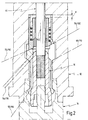
- FIG. 1 shows the state the spindle 10, in which the tool holder 14 has not yet been clamped is. Rather, the tool holder 14 is only loose inserted from below into the receiving opening of the spindle head 12 until the tool holder 14 and the spindle head 12 lie against each other in the radial plane 36.
- This pulling motion causes the segments 60 to be axially relative move to mandrel 18.
- the segments 60 are namely axially movable relative to the mandrel 18.
- the thickened heads 62 slide of the segments 60 on the guidance of the slopes 50/64 on the thickened lower end of the mandrel 18 and thus radially outward.
- the thickened heads Place 62 in the undercut 33 and thus the tool holder 14 in the spindle head 12.
- the segments 60 are also at their axially upper End moved radially outwards.
- this is achieved by that the mandrel 18 with the second slope 54 on his axially rear end on the eighth slope 78 at the bottom and inner end of the guide section 66 runs and the guide section 66 simultaneously with its bottom and outside, fourth slope 68 to the fifth slope 70 in the housing of the spindle head 12.
- the spindle 10 is now in the second operating position 2, in which the tool holder 14 firmly in the Spindle head 12 is clamped.
- an intermediate position can remain an additional one Leadership provided both in the first operating position 1 as in all intermediate positions acts up to the second operating position according to FIG. 2.
- This further guidance is composed by the seventh slope 76 formed with the tenth slope 100.
Landscapes
- Engineering & Computer Science (AREA)
- Mechanical Engineering (AREA)
- Gripping On Spindles (AREA)
Abstract
Description
- Fig. 1
- einen Axialschnitt durch ein Ausführungsbeispiel einer erfindungsgemäßen Spindel, in einer ersten Betriebsstellung, in der sich ein Spannmechanismus der Anordnung im ungespannten Zustand befindet;
- Fig. 2
- eine Darstellung, ähnlich Fig. 1, jedoch für eine zweite Betriebsstellung, in der ein Werkzeughalter in die Spindel eingespannt ist;
- Fig. 3
- im vergrößerten Maßstab und als perspektivische Ansicht ein Detail aus einem Segment, wie es bei der Spindel gemäß Fig. 1 und 2 verwendet wird.
Claims (17)
- Spindel in einer Werkzeugmaschine mit einer Achse (46), mit einer in der Achse (46) liegenden Aufnahme (34) für einen Schaft (30) eines Werkzeughalters (14), und mit einem Spannmechanismus zum axialen Fixieren des Schaftes (30) in der Aufnahme (34), wobei der Spannmechanismus einen axial verschiebbaren Spanndorn (18) sowie mindestens ein auf einem Umfang des Spanndorns (18) angeordnetes Segment (60) enthält, das bei axialer Verschiebung des Spanndorns (18) mittels einer zwischen dem Spanndorn (18) und den Segmenten (60) wirkenden ersten Führung (50/64, 54/78, 68/70, 72/92) zwischen einer ersten und einer zweiten radialen Betriebsstellung radial bewegbar ist und in der ersten Betriebsstellung den Schaft (30) formschlüssig in der Aufnahme (34) fixiert, dadurch gekennzeichnet, daß eine zweite Führung (76/100) vorgesehen ist, mittels der das mindestens eine Segment (60) in der zweiten Betriebsstellung sowie in jeder Zwischenposition zwischen der ersten und der zweiten Betriebsstellung definiert gehalten wird.
- Spindel nach Anspruch 1, dadurch gekennzeichnet, daß das mindestens eine Segment (60) sich entlang der Achse (46) erstreckt, daß die erste Führung (50/64, 54/78, 68/70, 72/92) an beiden axialen Enden und die zweite Führung (76/100) nur an einem axialen Ende des Segments (60) angreift.
- Spindel nach Anspruch 2, dadurch gekennzeichnet, daß die zweite Führung (76/100) am von der Aufnahme (34) weg weisenden axialen Ende des mindestens einen Segments (60) angreift.
- Spindel nach einem oder mehreren der Ansprüche 1 bis 3, dadurch gekennzeichnet, daß die erste Führung (50/64, 54/78, 68/70, 72/92) in der zweiten Betriebsstellung nur am von der Aufnahme (34) weg weisenden axialen Ende des mindestens einen Segments (60) angreift.
- Spindel nach einem oder mehreren der Ansprüche 1 bis 4, dadurch gekennzeichnet, daß die Führungen (50/64, 54/78, 68/70, 72/92; 76/100) als Schrägführungen ausgebildet sind.
- Spindel nach Anspruch 5, dadurch gekennzeichnet, daß das mindestens eine Segment (60) eine im Radialschnitt im wesentlichen kreisbogenförmige Gestalt aufweist und daß die Schrägführungen (50/64, 54/78, 68/70, 72/92; 76/100) durch konischen Schrägen (50, 54, 64, 68, 70, 72, 76, 78, 92, 100) gebildet werden.
- Spindel nach einem oder mehreren der Ansprüche 1 bis 6, dadurch gekennzeichnet, daß eine Mehrzahl von Segmenten (60) über einen Außenumfang des Spanndorns (18) verteilt angeordnet ist.
- Spindel nach Anspruch 7, dadurch gekennzeichnet, daß die Segmente (60) an ihrem von der Aufnahme (34) abgewandten Ende in einer gemeinsamen Krone (80) gehalten sind, und daß die Krone (80) mit ersten konischen Schrägen (92) versehen ist, die mit zweiten konischen Schrägen (72) an den Segmenten (60) als Bestandteil der ersten Führung (50/64, 54/78, 68/70, 72/92) zusammenarbeiten.
- Spindel nach Anspruch 8, dadurch gekennzeichnet, daß die Krone (80) beim axialen Verschieben des Spanndorns (18) gegen die Kraft einer Feder (88) axial verspannt wird.
- Spindel nach Anspruch 9, dadurch gekennzeichnet, daß die Feder (88) in der zweiten Betriebsstellung entspannt ist.
- Spindel nach Anspruch 9 oder 10, dadurch gekennzeichnet, daß die Krone (80) einen die Feder (88) haltenden, zylindrischen Abschnitt (82) sowie eine Mehrzahl von axial vorstehenden Schuhen (86) aufweist, an denen die ersten konischen Schrägen (92) angeformt sind.
- Spindel nach einem oder mehreren der Ansprüche 8 bis 11, dadurch gekennzeichnet, daß im axialen Bereich der Krone (80) eine zur Krone (80) koaxial ausgebildete Hülse (96) angeordnet ist und daß die Hülse (96) mit dritten konischen Schrägen (100) versehen ist, die mit vierten konischen Schrägen (76) an den Segmenten (60) als zweite Führung (76/100) zusammenarbeiten.
- Spindel nach Anspruch 12, dadurch gekennzeichnet, daß die erste/zweite Schräge (92/72) entgegengesetzt zur dritten/vierten Schräge (100/76) geneigt ist.
- Spindel nach Anspruch 12 oder 13, dadurch gekennzeichnet, daß die Hülse (96) axial fest angeordnet ist.
- Spindel nach einem oder mehreren der Ansprüche 12 bis 14, dadurch gekennzeichnet, daß die Krone (80) sich radial außen und die Hülse (96) sich radial innen befindet.
- Spindel nach Anspruch 15, dadurch gekennzeichnet, daß die Krone (80) in einer Bohrung (84) der Spindel (10) geführt ist.
- Spindel nach einem oder mehreren der Ansprüch 12 bis 14, dadurch gekennzeichnet, daß die Krone sich radial innen und die Hülse sich radial außen befindet.
Applications Claiming Priority (2)
| Application Number | Priority Date | Filing Date | Title |
|---|---|---|---|
| DE10031027A DE10031027B4 (de) | 2000-06-26 | 2000-06-26 | Spannmechanismus für eine Spindel in einer Werkzeugmaschine |
| DE10031027 | 2000-06-26 |
Publications (2)
| Publication Number | Publication Date |
|---|---|
| EP1166932A1 true EP1166932A1 (de) | 2002-01-02 |
| EP1166932B1 EP1166932B1 (de) | 2007-03-28 |
Family
ID=7646805
Family Applications (1)
| Application Number | Title | Priority Date | Filing Date |
|---|---|---|---|
| EP01113246A Expired - Lifetime EP1166932B1 (de) | 2000-06-26 | 2001-05-31 | Spindel in einer Werkzeugmaschine |
Country Status (5)
| Country | Link |
|---|---|
| US (1) | US6481940B2 (de) |
| EP (1) | EP1166932B1 (de) |
| JP (1) | JP4676093B2 (de) |
| DE (2) | DE10031027B4 (de) |
| ES (1) | ES2281387T3 (de) |
Cited By (4)
| Publication number | Priority date | Publication date | Assignee | Title |
|---|---|---|---|---|
| EP1955796A1 (de) * | 2007-02-12 | 2008-08-13 | Ott-Jakob Spanntechnik GmbH | Spannvorrichtung |
| WO2014020135A1 (de) * | 2012-08-02 | 2014-02-06 | Haimer Gmbh | Auswucht- oder messadapter |
| US20230102601A1 (en) * | 2021-09-30 | 2023-03-30 | Precision Machinery Research & Development Center | Tool changing mechanism having function of controlling loosening and pulling tool |
| EP4190472A1 (de) * | 2021-12-03 | 2023-06-07 | Franz Haimer Maschinenbau KG | Spannvorrichtung zum spannen eines bauteils an einem maschinenelement einer bearbeitungsmaschine |
Families Citing this family (23)
| Publication number | Priority date | Publication date | Assignee | Title |
|---|---|---|---|---|
| DE10159611C1 (de) * | 2001-12-05 | 2003-05-28 | Ott Jakob Spanntech Gmbh & Co | Spannvorrichtung |
| US20030206780A1 (en) * | 2002-01-02 | 2003-11-06 | Hsi-Kuan Chen | Spindle assembly for a machine tool |
| DE10338610B4 (de) * | 2003-08-22 | 2015-05-07 | MAPAL Fabrik für Präzisionswerkzeuge Dr. Kress KG | Schnittstelle |
| DE10342951B3 (de) * | 2003-09-17 | 2005-04-28 | Ott Jakob Spanntech Gmbh & Co | Spannvorrichtung |
| US7137632B2 (en) * | 2003-10-27 | 2006-11-21 | Hardinge Inc. | Force limiting workpiece holding device |
| CZ298422B6 (cs) * | 2003-12-09 | 2007-09-26 | Západoceská Univerzita V Plzni | Zpusob upínání a uvolnování nástroje s dutým strmým kuželem HSK a zarízení k uskutecnování tohoto zpusobu |
| DE102004029043A1 (de) | 2004-06-14 | 2006-01-05 | Chiron-Werke Gmbh & Co Kg | Werkzeugmaschine und Verfahren zum Wechsel von Werkzeugen an dieser Werkzeugmaschine |
| DE102005016870A1 (de) * | 2005-04-07 | 2006-10-12 | Kaltenbach & Voigt Gmbh | Medizinisches, insbesondere dentalmedizinisches, Handstück mit einer lösbaren Kupplung für einen Werkzeughalter |
| DE102005016869A1 (de) * | 2005-04-07 | 2006-10-12 | Kaltenbach & Voigt Gmbh | Medizinisches Handstück mit einer Spannzange |
| DE202005014350U1 (de) * | 2005-09-09 | 2005-11-10 | Haimer Gmbh | Werkzeughalter zur Schrumpfbefestigung von Werkzeugen |
| DE102007016490B4 (de) * | 2007-04-05 | 2016-12-29 | Narr Beteiligungs Gmbh | Handhabungsvorrichtung |
| DE102007044114B4 (de) | 2007-09-16 | 2010-06-17 | Chiron-Werke Gmbh & Co. Kg | Werkzeugmaschine |
| DE102008022826A1 (de) * | 2008-05-07 | 2009-11-12 | Röhm Gmbh | Spannkopf |
| DE102008054251B3 (de) * | 2008-10-24 | 2010-04-08 | Chiron-Werke Gmbh & Co. Kg | Verfahren zur Überwachung der Anlage bei einem Werkzeughalter |
| KR101044344B1 (ko) | 2009-05-20 | 2011-06-29 | 박상민 | 툴 클램핑 장치 |
| DE102009037617B3 (de) | 2009-08-14 | 2011-03-24 | Ott-Jakob Spanntechnik Gmbh | Gasdruckfeder und Spannvorrichtung mit einer derartigen Gasdruckfeder |
| JP5337009B2 (ja) * | 2009-11-30 | 2013-11-06 | 理研精機株式会社 | 工具ホルダー保持体 |
| DE102011116818B4 (de) | 2011-10-22 | 2015-04-09 | Ott-Jakob Spanntechnik Gmbh | Löseeinheit zur Betätigung eines Spannmechanismus |
| US20130147131A1 (en) * | 2011-12-08 | 2013-06-13 | Aerotech, Inc. | Rotary Stage With Integrated Collet Closer Assembly |
| CN103567759A (zh) * | 2012-08-10 | 2014-02-12 | 湖北奥德车桥有限公司 | 一种汽车驱动桥整体桥壳的轴头成型机 |
| DE102013107791B4 (de) | 2013-07-22 | 2017-05-04 | Chiron-Werke Gmbh & Co. Kg | Werkzeugmaschine |
| US10850332B1 (en) * | 2019-06-11 | 2020-12-01 | Kennametal Inc. | Hollow shank tool holder |
| EP3875193B1 (de) * | 2020-03-05 | 2024-05-01 | Schaublin SA | Klemmvorrichtung zum klemmen eines werkzeugs oder werkstücks |
Citations (1)
| Publication number | Priority date | Publication date | Assignee | Title |
|---|---|---|---|---|
| EP0787549A1 (de) * | 1996-02-01 | 1997-08-06 | Niigata Engineering Co., Ltd. | Hauptspindeleinrichtung für Werkzeugmaschinen |
Family Cites Families (6)
| Publication number | Priority date | Publication date | Assignee | Title |
|---|---|---|---|---|
| US3323419A (en) * | 1963-08-20 | 1967-06-06 | Kearney & Trecker Corp | Spindle chuck device |
| DE8816782U1 (de) * | 1987-05-11 | 1990-06-21 | Gühring oHG, 72458 Albstadt | Kupplungsvorrichtung zwischen einem Werkstück- oder Werkzeugträgerteil und einer dafür vorgesehenen Handhabungseinrichtung |
| DE3814550C1 (en) * | 1988-04-29 | 1989-09-28 | A. Ott Gmbh, 8960 Kempten, De | Clamping device for clamping two machine parts releasable from one another |
| DE8805690U1 (de) * | 1988-04-29 | 1989-08-31 | A. Ott Gmbh, 8960 Kempten | Spannvorrichtung zum axialen Spannen zweier voneinander lösbarer Maschinenteile |
| US5613929A (en) * | 1995-06-07 | 1997-03-25 | Hurco Companies, Inc. | Machine tool with bar-spindle and DIN standard toolholder changer |
| JPH10118814A (ja) * | 1996-10-23 | 1998-05-12 | Hitachi Seiki Co Ltd | 工作機械の主軸における工具ホルダの仮保持装置 |
-
2000
- 2000-06-26 DE DE10031027A patent/DE10031027B4/de not_active Expired - Fee Related
-
2001
- 2001-05-31 ES ES01113246T patent/ES2281387T3/es not_active Expired - Lifetime
- 2001-05-31 EP EP01113246A patent/EP1166932B1/de not_active Expired - Lifetime
- 2001-05-31 DE DE50112257T patent/DE50112257D1/de not_active Expired - Lifetime
- 2001-06-25 US US09/891,056 patent/US6481940B2/en not_active Expired - Lifetime
- 2001-06-25 JP JP2001191116A patent/JP4676093B2/ja not_active Expired - Fee Related
Patent Citations (1)
| Publication number | Priority date | Publication date | Assignee | Title |
|---|---|---|---|---|
| EP0787549A1 (de) * | 1996-02-01 | 1997-08-06 | Niigata Engineering Co., Ltd. | Hauptspindeleinrichtung für Werkzeugmaschinen |
Cited By (6)
| Publication number | Priority date | Publication date | Assignee | Title |
|---|---|---|---|---|
| EP1955796A1 (de) * | 2007-02-12 | 2008-08-13 | Ott-Jakob Spanntechnik GmbH | Spannvorrichtung |
| WO2014020135A1 (de) * | 2012-08-02 | 2014-02-06 | Haimer Gmbh | Auswucht- oder messadapter |
| US9694429B2 (en) | 2012-08-02 | 2017-07-04 | Haimer Gmbh | Balancing or measuring adapter |
| US20230102601A1 (en) * | 2021-09-30 | 2023-03-30 | Precision Machinery Research & Development Center | Tool changing mechanism having function of controlling loosening and pulling tool |
| US11992911B2 (en) * | 2021-09-30 | 2024-05-28 | Precision Machinery Research & Development Center | Tool changing mechanism having function of controlling loosening and pulling tool |
| EP4190472A1 (de) * | 2021-12-03 | 2023-06-07 | Franz Haimer Maschinenbau KG | Spannvorrichtung zum spannen eines bauteils an einem maschinenelement einer bearbeitungsmaschine |
Also Published As
| Publication number | Publication date |
|---|---|
| DE50112257D1 (de) | 2007-05-10 |
| JP4676093B2 (ja) | 2011-04-27 |
| US20020014141A1 (en) | 2002-02-07 |
| JP2002036010A (ja) | 2002-02-05 |
| DE10031027B4 (de) | 2004-03-04 |
| EP1166932B1 (de) | 2007-03-28 |
| ES2281387T3 (es) | 2007-10-01 |
| DE10031027A1 (de) | 2002-01-24 |
| US6481940B2 (en) | 2002-11-19 |
Similar Documents
| Publication | Publication Date | Title |
|---|---|---|
| DE10031027B4 (de) | Spannmechanismus für eine Spindel in einer Werkzeugmaschine | |
| DE3414300C2 (de) | ||
| DE102006038407B4 (de) | Verriegelndes Spannfutter | |
| WO2007147711A1 (de) | Trennstelle zwischen zwei teilelementen eines drehenden werkzeugsystems | |
| DE2715357A1 (de) | Werkzeugaufnahmevorrichtung | |
| DE3712820C2 (de) | ||
| DE3031216C2 (de) | Spannfutter für Gewindebohrer | |
| DE8335933U1 (de) | Automatisches Stifteintreibwerkzeug | |
| DE3939227A1 (de) | Spannvorrichtung zum axialen spannen eines werkzeugkopfes an einer werkzeugmaschinenspindel | |
| DE3632045C1 (de) | Vorrichtung zur Verbindung zweier Werkzeugteile | |
| CH651636A5 (de) | Anordnung zur befestigung eines gegenstandes an einer wand, verfahren zur herstellung dieser anordnung sowie werkzeug zur durchfuehrung des verfahrens. | |
| EP0275441B1 (de) | Spannvorrichtung | |
| CH671719A5 (de) | ||
| EP3016770B2 (de) | Wechselkopfsystem für die metallbearbeitung | |
| EP1709931B1 (de) | Motorelement, insbesondere dentalmedizinisches Handstück mit einer lösbaren Kupplung für einen Werkzeughalter | |
| DE2647633C2 (de) | Werkzeughalter | |
| DE1602760A1 (de) | Bohrstangeneinsatz zum verstellbaren Halten eines Werkzeuges in gewaehlten Stellungenin einer Bohrstange | |
| DE10338610B4 (de) | Schnittstelle | |
| DE3315661C2 (de) | Spannfutter für ein Werkzeug zum Schlagbohren | |
| DE2817636A1 (de) | Werkzeug zur wiederherstellung eines ventilsitzes | |
| EP1477269B1 (de) | Werkzeugmaschine | |
| DE2305133A1 (de) | Bohrvorrichtung mit einer bohrspindel und einem in senkrechter ebene vor dieser bewegbaren magazin | |
| DE1959770C3 (de) | Gewindeschneidfutter | |
| WO1993002822A1 (de) | Spannzangenfutter | |
| DE3323709C2 (de) | Gewindeschneidfutter |
Legal Events
| Date | Code | Title | Description |
|---|---|---|---|
| PUAI | Public reference made under article 153(3) epc to a published international application that has entered the european phase |
Free format text: ORIGINAL CODE: 0009012 |
|
| AK | Designated contracting states |
Kind code of ref document: A1 Designated state(s): DE ES FR GB IT Kind code of ref document: A1 Designated state(s): AT BE CH CY DE DK ES FI FR GB GR IE IT LI LU MC NL PT SE TR |
|
| AX | Request for extension of the european patent |
Free format text: AL;LT;LV;MK;RO;SI |
|
| 17P | Request for examination filed |
Effective date: 20011214 |
|
| AKX | Designation fees paid |
Free format text: DE ES FR GB IT |
|
| 17Q | First examination report despatched |
Effective date: 20050303 |
|
| RAP1 | Party data changed (applicant data changed or rights of an application transferred) |
Owner name: OTT-JAKOB GMBH & CO. SPANNTECHNIK KG |
|
| GRAP | Despatch of communication of intention to grant a patent |
Free format text: ORIGINAL CODE: EPIDOSNIGR1 |
|
| GRAS | Grant fee paid |
Free format text: ORIGINAL CODE: EPIDOSNIGR3 |
|
| GRAA | (expected) grant |
Free format text: ORIGINAL CODE: 0009210 |
|
| AK | Designated contracting states |
Kind code of ref document: B1 Designated state(s): DE ES FR GB IT |
|
| REG | Reference to a national code |
Ref country code: GB Ref legal event code: FG4D Free format text: NOT ENGLISH |
|
| REF | Corresponds to: |
Ref document number: 50112257 Country of ref document: DE Date of ref document: 20070510 Kind code of ref document: P |
|
| GBT | Gb: translation of ep patent filed (gb section 77(6)(a)/1977) |
Effective date: 20070705 |
|
| ET | Fr: translation filed | ||
| REG | Reference to a national code |
Ref country code: ES Ref legal event code: FG2A Ref document number: 2281387 Country of ref document: ES Kind code of ref document: T3 |
|
| PLBE | No opposition filed within time limit |
Free format text: ORIGINAL CODE: 0009261 |
|
| STAA | Information on the status of an ep patent application or granted ep patent |
Free format text: STATUS: NO OPPOSITION FILED WITHIN TIME LIMIT |
|
| 26N | No opposition filed |
Effective date: 20080102 |
|
| REG | Reference to a national code |
Ref country code: FR Ref legal event code: PLFP Year of fee payment: 16 |
|
| REG | Reference to a national code |
Ref country code: FR Ref legal event code: PLFP Year of fee payment: 17 |
|
| REG | Reference to a national code |
Ref country code: FR Ref legal event code: PLFP Year of fee payment: 18 |
|
| PGFP | Annual fee paid to national office [announced via postgrant information from national office to epo] |
Ref country code: CH Payment date: 20170927 Year of fee payment: 13 |
|
| PGFP | Annual fee paid to national office [announced via postgrant information from national office to epo] |
Ref country code: DE Payment date: 20190503 Year of fee payment: 19 Ref country code: ES Payment date: 20190601 Year of fee payment: 19 |
|
| PGFP | Annual fee paid to national office [announced via postgrant information from national office to epo] |
Ref country code: GB Payment date: 20190513 Year of fee payment: 19 |
|
| PG25 | Lapsed in a contracting state [announced via postgrant information from national office to epo] |
Ref country code: FR Free format text: LAPSE BECAUSE OF NON-PAYMENT OF DUE FEES Effective date: 20190531 |
|
| PGFP | Annual fee paid to national office [announced via postgrant information from national office to epo] |
Ref country code: IT Payment date: 20200528 Year of fee payment: 20 |
|
| REG | Reference to a national code |
Ref country code: DE Ref legal event code: R119 Ref document number: 50112257 Country of ref document: DE |
|
| GBPC | Gb: european patent ceased through non-payment of renewal fee |
Effective date: 20200531 |
|
| PG25 | Lapsed in a contracting state [announced via postgrant information from national office to epo] |
Ref country code: GB Free format text: LAPSE BECAUSE OF NON-PAYMENT OF DUE FEES Effective date: 20200531 |
|
| PG25 | Lapsed in a contracting state [announced via postgrant information from national office to epo] |
Ref country code: DE Free format text: LAPSE BECAUSE OF NON-PAYMENT OF DUE FEES Effective date: 20201201 |
|
| PG25 | Lapsed in a contracting state [announced via postgrant information from national office to epo] |
Ref country code: ES Free format text: LAPSE BECAUSE OF NON-PAYMENT OF DUE FEES Effective date: 20200601 |