EP1166934A2 - Hochgeschwindigkeitsschere mit einstellbaren Messertrommeln - Google Patents
Hochgeschwindigkeitsschere mit einstellbaren Messertrommeln Download PDFInfo
- Publication number
- EP1166934A2 EP1166934A2 EP01113484A EP01113484A EP1166934A2 EP 1166934 A2 EP1166934 A2 EP 1166934A2 EP 01113484 A EP01113484 A EP 01113484A EP 01113484 A EP01113484 A EP 01113484A EP 1166934 A2 EP1166934 A2 EP 1166934A2
- Authority
- EP
- European Patent Office
- Prior art keywords
- knife
- drums
- drum
- eccentrics
- speed
- Prior art date
- Legal status (The legal status is an assumption and is not a legal conclusion. Google has not performed a legal analysis and makes no representation as to the accuracy of the status listed.)
- Granted
Links
- 238000005520 cutting process Methods 0.000 title abstract description 16
- 230000007246 mechanism Effects 0.000 claims description 9
- 238000005516 engineering process Methods 0.000 claims description 2
- 238000000926 separation method Methods 0.000 abstract 1
- 230000005540 biological transmission Effects 0.000 description 4
- 230000001360 synchronised effect Effects 0.000 description 4
- 230000008878 coupling Effects 0.000 description 2
- 238000010168 coupling process Methods 0.000 description 2
- 238000005859 coupling reaction Methods 0.000 description 2
- 238000010586 diagram Methods 0.000 description 2
- 238000005096 rolling process Methods 0.000 description 2
- 208000019300 CLIPPERS Diseases 0.000 description 1
- 230000000712 assembly Effects 0.000 description 1
- 238000000429 assembly Methods 0.000 description 1
- 230000008901 benefit Effects 0.000 description 1
- 230000008859 change Effects 0.000 description 1
- 208000021930 chronic lymphocytic inflammation with pontine perivascular enhancement responsive to steroids Diseases 0.000 description 1
- 238000010276 construction Methods 0.000 description 1
- 239000000463 material Substances 0.000 description 1
- 239000002184 metal Substances 0.000 description 1
- 230000002093 peripheral effect Effects 0.000 description 1
- 238000010008 shearing Methods 0.000 description 1
- 230000007480 spreading Effects 0.000 description 1
- 238000003892 spreading Methods 0.000 description 1
- 238000003860 storage Methods 0.000 description 1
Images


Classifications
-
- B—PERFORMING OPERATIONS; TRANSPORTING
- B23—MACHINE TOOLS; METAL-WORKING NOT OTHERWISE PROVIDED FOR
- B23D—PLANING; SLOTTING; SHEARING; BROACHING; SAWING; FILING; SCRAPING; LIKE OPERATIONS FOR WORKING METAL BY REMOVING MATERIAL, NOT OTHERWISE PROVIDED FOR
- B23D35/00—Tools for shearing machines or shearing devices; Holders or chucks for shearing tools
- B23D35/005—Adjusting the position of the cutting members
-
- B—PERFORMING OPERATIONS; TRANSPORTING
- B23—MACHINE TOOLS; METAL-WORKING NOT OTHERWISE PROVIDED FOR
- B23D—PLANING; SLOTTING; SHEARING; BROACHING; SAWING; FILING; SCRAPING; LIKE OPERATIONS FOR WORKING METAL BY REMOVING MATERIAL, NOT OTHERWISE PROVIDED FOR
- B23D25/00—Machines or arrangements for shearing stock while the latter is travelling otherwise than in the direction of the cut
- B23D25/12—Shearing machines with blades on coacting rotating drums
Definitions
- the invention relates to a high-speed shear for dividing cold and / or hot strip by means of at least one knife drum, which is in a scissor housing are employable.
- High-speed shears for cross-cutting of hot in mill stands and / or cold-rolled strip are known in different designs.
- German published patent application DE 197 46 528 A describes a high-speed shear, comprising two drums, one with a chisel knife and the other equipped with a co-operating anvil or is designed as such. With the help of a controlled actuator both drums become the cutting process of a continuous rolled strip moved against each other.
- the two drums are synchronized by means of electrical, electronic or transmission technology means.
- EP 0 904 877 A2 discloses a high-speed shear with knife drums of slightly different diameters, with the speed difference are driven by an external branching gear. With With the help of an adjusting device using a spreading lever, the drums on the opposite side Position of the knives in the cutting position and after the successful Cut of the rolled strip moved away from each other again.
- German Offenlegungsschrift 26 54 866 describes a flying clipper the rotary drum type with rotary drums coupled together.
- the scissors include a drum rotator with one of both drums Coupling power transmission for speeds synchronized with the running speed of the supplied material, also a drum actuator for adjusting a shaving drum between an open position and one Cutting position, and a control device for the motor of the actuating device, which starts the first shear drum and starts in the Cutting position and moving the drum back to the starting position controls.
- the first and second knife drums have a diameter ratio of 2 3 and are translated so that three revolutions of the first Drum two turns of the second drum and the drum actuator is controlled so that the first drum after 6 revolutions and the second drum after 4 revolutions for a cutting operation meet.
- EP 0 990 478 A1 describes continuously rotatable scissors, one by one continuously fed metal strip at approx. 20 m / sec with a thickness of 0.5 up to 5 mm and a width between 500 and 1500 mm in specified dimensions to cut, comprising two knife drums with terminal rotatable Trunnion controlled by control means.
- the drums are between Side parts of a scissor frame mounted and have external drive means including gear assemblies with outer gears that hold the drums drive together.
- DE 41 28 970 A1 describes a shearing device with an upper and a lower drum, each provided with a blade and facing each other are spaced by a hydraulic cylinder until the rotational speed of the Drumming has been accelerated to a predetermined value.
- the drums are brought together by the cylinder, so that the Shafts of the corresponding drums arranged gears with each other Intervene to maintain a constant gap between the blades.
- the blades are brought closer to the feed line of the strip to be cut, to cut the strip off.
- DE-OS 196 37 862 A1 describes a high-speed shear for Cross sections of rolled strip. It is a pair of flying scissors opposing drums arranged knife edges on Feed speed of the strip to be cut can be accelerated and Perform a cut against each other.
- the opposing drums are characterized by the opposing drums by at least one drive device assigned to them at one speed corresponding circumferential speed of the band to be cut can be accelerated, and that at least one of the drums is a separate one controllable adjusting device is assigned. At least one of the drums is mounted on rockers, which are connected to the adjusting devices.
- One of the drums is equipped with a knife, the one with an anvil acting jacket region of the second drum cooperates, the peripheral speed can be synchronized from drums to the belt feed speed is.
- Wo 99/46 076 describes flying scissors for thin hot strip. This should be designed so that very fast running tape is cut safely.
- one of the cutting tool drums is mounted on a rocker arm, that an adjusting device consists of drives causing the cutting movement and support elements arranged between them and the rockers, and that the support elements can be shortened to an effective position causing cuts.
- the task is the high-speed shear of the aforementioned Genre solved in that the knife drums (one or two drums) in Scissor housing are adjustably mounted by means of eccentric, the drive of the Eccentrically via at least one balancer shaft, that of a drum shaft is drivable, which in turn is connected to a rotary drive.
- the high-speed scissors are preferably designed in such a way that that two knife drums are mounted in the scissor housing in eccentric bushings and the eccentrics can each be driven via a balance shaft, as well as the balance shafts are technically connected to each other, and that the balance shafts are arranged by means of a lever mechanism so that they remain unchanged the same center distance to the drums and to each other to have.
- the second balancer shaft drives the second knife drum , whereby the power flow from the first knife drum through the first balancer shaft, on the second balancer shaft and from this to the second knife drum he follows.
- the constant center distance set by the lever mechanism enables a low backlash in the teeth, which creates a Pre-synchronization of the knife drums is achieved.
- Another embodiment of the invention provides that the eccentric bushings, for example are braced against each other by means of spring-actuated setting wheels. This ensures that the knife drums are positioned exactly in the cut.
- FIG. 1 of the high-speed shears according to the invention for cross cutting of cold and / or hot rolled rolled strip comprises a first knife drum 1 and a second knife drum 2, the are stored within a scissor housing 15.
- drivers 18, 19 are provided, the rolling belt 17, under longitudinal tension in front of and behind the knife drums 1, 2, pass through the drum gap, this under tension standing rolled strip 17, during its transport through the high-speed shears is mounted on transfer rollers 20, 20 'which lift the rolled strip, or lower.
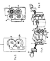
- FIGS. 2 and 3 show that the knife drums 1, 2 in eccentrics 3, 4 can be raised and lowered, i.e. adjusted, stored.
- the drive of the Exenter 3 takes place according to Figure 4 via a balance shaft 7, which is from the first drum shaft 1 is driven.
- a second balance shaft 8 is from the first balance shaft 7 driven.
- the second balancer shaft 8 drives the second knife drum 2 on.
- the balance shafts 7, 8 are arranged according to Figure 4 so that they always the same center distance to the knife drums 1, 2 and to each other to have. This is achieved by a lever mechanism with the elements 9 to 12. The constant center distance leaves a small tooth play in the gears to. This pre-synchronizes the knife drums 1, 2 reached.
- the first balancer shaft 7 drives the first in accordance with FIGS. 5 and 6 Eccentric bushing 3 on, the first eccentric bushing 3 drives the second eccentric bushing 4 on. Both eccentric bushes are braced against each other by setting wheels 4a. This ensures that both drums are positioned exactly in the cut are.
- the knife drum 1 has a rotary drive by means of an electric motor 13 via a conventional cardan shaft 21 and an intermediate gear 22. It can also be another Drive type can be selected as with an electric motor.
- the other knife drum 2 has a brake 14, preferably an electric brake 14. This ensures that no detachment of the load flanks and no unwanted edge change can take place.
- one knife drum 1 or both knife drums 1, 2, preferably by means of the eccentric 3, 4, can be electrically or mechanically the rotary drive 13 for the one knife drum 2 can be synchronized.
- the knife drums 1, 2 can cut to the high belt speed with simultaneous synchronization of the infeed movement over several revolutions be accelerated, or the knife drums 1, 2 rotate with the current one Belt speed and are only delivered.
- Figures 4 and 5 show in an enlarged view and from different Viewing angles and / or cutting planes of the high-speed scissors according to the invention with the individual components.
- Figures 4 and 5 are special clearly see the two balancer shafts 7 and 8, which are together are technically connected, as well as the components 9 to 12 of the lever mechanism, with which the balance shafts 7, 8 are always arranged in this way are that they have the same center distance to the knife drums 1, 2 as well as with each other.
- Figure 6 shows the eccentric bushes 4, 4a and On the opposite side, the spring-operated setting wheel 6a on the second knife drum 2.
- the high-speed shear described above and shown in the figures is particularly suitable for cutting cold and / or hot rolled Rolling strip with a thickness of 0.15 mm to 6 mm for strip widths up to 2,500 mm and Cutting speeds up to 30 m / sec.
- the storage of the knife drums 1, 2 and the eccentrics 3, 4, and the balance shafts 7, 8 in the scissor housing 15 enables a compact Construction.
- the synchronization of both knife drums 1, 2 by the balance shafts 7, 8 result in significant progress.
- the main synchronization the knife drums 1, 2 are advantageously carried out by spring-operated comb wheels.
Landscapes
- Engineering & Computer Science (AREA)
- Mechanical Engineering (AREA)
- Shearing Machines (AREA)
- Details Of Cutting Devices (AREA)
- Control Of Cutting Processes (AREA)
- Mechanical Treatment Of Semiconductor (AREA)
Abstract
Description
Diese soll so ausgebildet werden, dass sehr schnell laufendes Band sicher geschnitten wird. Dazu wird vorgeschlagen, dass eine der Schneidwerkzeugtrommeln auf einer Schwinge gelagert ist, dass eine Anstellvorrichtung aus die Schneidbewegung bewirkenden Antrieben und zwischen diesen und den Schwingen angeordneten Stützelementen besteht, und dass die Stützelemente auf eine Schnitte bewirkende Wirkstellung verkürzbar sind.
- Figur 1
- ein Funktionsschema der erfindungsgemäßen Hochgeschwindigkeitsschere:
- Figur 2
- eine Ansicht der abstandsveränderlichen Position beider Messertrommeln;
- Figur 3
- in Ansicht die Exzenteranordnung;
- Figur 4
- eine perspektivische Ansicht der Schere schräg von vorn;
- Figur 5
- eine perspektivische Ansicht der Schere schräg von hinten;
- Figur 6
- die Schere im Schnitt einer Ebene entlang der Achse der Messertrommeln;
- Figur 7
- eine perspektivische Ansicht der Schere in einem Scherengehäuse;
- Figur 8
- eine Ansicht der Schere im Schnitt einer Ebene entlang der Ausgleichswellen.
- 1
- Messertrommel
- 2
- Messertrommel
- 3
- Exzenter/Buchse, erste
- 4
- Exzenter/Buchse, zweite
- 4a
- Einstellrad
- 5
- Kammrad
- 6
- Kammrad
- 6a
- Einstellrad
- 7
- Ausgleichswelle
- 8
- Ausgleichswelle
- 9
- Hebelmechanismus
- 10
- Hebelmechanismus
- 11
- Hebelmechanismus
- 12
- Hebelmechanismus
- 13
- Elektromotor
- 14
- Bremse
- 15
- Scherengehäuse
- 16
- Laufrichtung Band
- 17
- Walzband
- 18
- Treiber
- 19
- Treiber
- 20
- Überführungsrollen
- 20'
- Überführungsrollen
- 21
- Gelenkwelle
- 22
- Antriebsgetriebe
Claims (4)
- Hochgeschwindigkeitsschere zum Teilen bzw. Trennen von Kalt- und/oder Warmband mittels wenigstens einer Messertrommel, die in einem Scherengehäuse anstellbar gelagert sind,
dadurch gekennzeichnet, daß die Messertrommel (1, 2) im Scherengehäuse (15) mittels Exenter (3, 4) anstellbar gelagert sind, wobei der Antrieb der Exenter (3, 4) über wenigstens eine Ausgleichswelle (7, 8) erfolgt, die von einer Trommelwelle (1) antreibbar ist, welche ihrerseits mit einem Drehantrieb (13) in Verbindung steht. - Hochgeschwindigkeitsschere nach Anspruch 1,
dadurch gekennzeichnet, daß zwei Messertrommeln (1, 2) im Scherengehäuse (15) in Exenterbuchsen (3, 4) gelagert sind, die Exenter jeweils über eine Ausgleichswelle (7, 8) antreibbar sind, die Ausgleichswellen (7, 8) getriebetechnisch miteinander verbunden sind, und daß die Ausgleichswellen (7, 8) so angeordnet sind, daß sie mittels eines Hebelmechanismus (9 bis 12) unverändert den gleichen Achsenabstand zu den Messertrommeln (1, 2) sowie untereinander haben. - Hochgeschwindigkeitsschere nach Anspruch 1 oder 2,
dadurch gekennzeichnet, daß die Exenterbuchsen (3, 4) beispielsweise mittels wenigstens eines federbetätigten Einstellrades (6a) gegeneinander verspannt sind. - Hochgeschwindigkeitsschere nach Anspruch 1, 2, oder 3,
dadurch gekennzeichnet, daß die eine Messertrommel (1) mit dem Drehantrieb (13) und die andere Messertrommel mit einer Bremse (14), vorzugsweise einer elektrischen Bremse verbunden ist.
Applications Claiming Priority (4)
| Application Number | Priority Date | Filing Date | Title |
|---|---|---|---|
| DE10030309 | 2000-06-27 | ||
| DE2000130309 DE10030309A1 (de) | 2000-06-27 | 2000-06-27 | Hochgeschwindigkeitsschere zum Teilen von Kalt- und/oder Warmband |
| DE10120617A DE10120617A1 (de) | 2000-06-27 | 2001-04-26 | Hochgeschwindigkeitsschere zum Teilen von Kalt- und/oder Warmband |
| DE10120617 | 2001-04-26 |
Publications (3)
| Publication Number | Publication Date |
|---|---|
| EP1166934A2 true EP1166934A2 (de) | 2002-01-02 |
| EP1166934A3 EP1166934A3 (de) | 2003-10-08 |
| EP1166934B1 EP1166934B1 (de) | 2006-05-03 |
Family
ID=26006150
Family Applications (1)
| Application Number | Title | Priority Date | Filing Date |
|---|---|---|---|
| EP01113484A Expired - Lifetime EP1166934B1 (de) | 2000-06-27 | 2001-06-02 | Hochgeschwindigkeitsschere mit einstellbaren Messertrommeln |
Country Status (4)
| Country | Link |
|---|---|
| EP (1) | EP1166934B1 (de) |
| AT (1) | ATE324958T1 (de) |
| DE (1) | DE50109669D1 (de) |
| ES (1) | ES2262577T3 (de) |
Cited By (3)
| Publication number | Priority date | Publication date | Assignee | Title |
|---|---|---|---|---|
| CN107755793A (zh) * | 2016-08-22 | 2018-03-06 | 江苏三环实业股份有限公司 | 一种切断机构 |
| CN109759632A (zh) * | 2019-03-21 | 2019-05-17 | 天津富瑞隆金属制品有限公司 | 一种可调节的纵剪机 |
| CN114144289A (zh) * | 2019-08-21 | 2022-03-04 | 柯尔布斯有限责任两合公司 | 用于生产书封皮、盒盖或者游戏板的设备 |
Family Cites Families (2)
| Publication number | Priority date | Publication date | Assignee | Title |
|---|---|---|---|---|
| US1948139A (en) * | 1931-08-17 | 1934-02-20 | United Eng Foundry Co | Rotary flying shear |
| US6032560A (en) * | 1997-10-24 | 2000-03-07 | Morgan Construction Company | High speed trimming shear |
-
2001
- 2001-06-02 DE DE50109669T patent/DE50109669D1/de not_active Expired - Lifetime
- 2001-06-02 AT AT01113484T patent/ATE324958T1/de active
- 2001-06-02 ES ES01113484T patent/ES2262577T3/es not_active Expired - Lifetime
- 2001-06-02 EP EP01113484A patent/EP1166934B1/de not_active Expired - Lifetime
Cited By (4)
| Publication number | Priority date | Publication date | Assignee | Title |
|---|---|---|---|---|
| CN107755793A (zh) * | 2016-08-22 | 2018-03-06 | 江苏三环实业股份有限公司 | 一种切断机构 |
| CN109759632A (zh) * | 2019-03-21 | 2019-05-17 | 天津富瑞隆金属制品有限公司 | 一种可调节的纵剪机 |
| CN114144289A (zh) * | 2019-08-21 | 2022-03-04 | 柯尔布斯有限责任两合公司 | 用于生产书封皮、盒盖或者游戏板的设备 |
| CN114144289B (zh) * | 2019-08-21 | 2024-05-10 | 柯尔布斯有限责任两合公司 | 用于生产书封皮、盒盖或者游戏板的设备 |
Also Published As
| Publication number | Publication date |
|---|---|
| ES2262577T3 (es) | 2006-12-01 |
| EP1166934A3 (de) | 2003-10-08 |
| EP1166934B1 (de) | 2006-05-03 |
| ATE324958T1 (de) | 2006-06-15 |
| DE50109669D1 (de) | 2006-06-08 |
Similar Documents
| Publication | Publication Date | Title |
|---|---|---|
| DE2436717A1 (de) | Schlitz- und falzvorrichtung fuer durchlaufende materialbahnen | |
| DE3140769C2 (de) | ||
| DE3416664C2 (de) | Einrichtung zum Steuern der Schneidgeschwindigkeit des Sägeblattes einer Bandsägemaschine | |
| DE19637862A1 (de) | Hochgeschwindigkeitsschere zum Querteilen von Walzband | |
| EP1099501B1 (de) | Hochgeschwindigkeitsschere zum Querteilen von Walzband | |
| DE3104496C2 (de) | Trommelschere | |
| DE4205781C2 (de) | Vorrichtung zum Zerkleinern von Schrott | |
| DE69814853T2 (de) | Verfahren sowie Vorrichtung zum Bewegen des Kreismessers einer Maschine zum Schneiden von Papierrollen oder dergleichen | |
| DE4416522A1 (de) | Papierbahn-Schneideeinrichtung | |
| DE2335966A1 (de) | Verfahren und vorrichtung zum schlitzen von metallstreifen | |
| EP1099502B1 (de) | Hochgeschwindigkeitsschere zum Querteilen von insbesondere dünnem Walzband | |
| EP1166934B1 (de) | Hochgeschwindigkeitsschere mit einstellbaren Messertrommeln | |
| DE2542402B2 (de) | Querschneider für Papierbahnen | |
| EP1068040B1 (de) | Hochgeschwindigkeitsschere zum querteilen von walzband | |
| DE3443849A1 (de) | Randabgratvorrichtung fuer stahlblechband | |
| EP1118409B1 (de) | Hochgeschwindigkeitsschere zum Querteilen von Walzband | |
| DE102019102404B4 (de) | Vorrichtung zum Schneiden eines mit einem Verstärkungselement versehenen Schlauchs | |
| DE10120617A1 (de) | Hochgeschwindigkeitsschere zum Teilen von Kalt- und/oder Warmband | |
| DE19756622B4 (de) | Doppelprofilschnittmaschine mit Längsverschiebung der Profile | |
| DE2441225A1 (de) | Vorrichtung zum bearbeiten von kontinuierlich durchlaufenden papierbahnen | |
| DE69901943T2 (de) | Verfahren und vorrichtung zum zerteilen von walzgut | |
| DE3543868A1 (de) | Raederfalzapparat | |
| DE4314008C2 (de) | Verfahren und Vorrichtung zur Herstellung von Stahlfasern | |
| EP1151819B1 (de) | Antriebskupplung für Trommelscheren | |
| DE19546255C1 (de) | Vorrichtung zum Abtrennen von Packungsstreifen von einer kontinuierlich bewegten Materialbahn |
Legal Events
| Date | Code | Title | Description |
|---|---|---|---|
| PUAI | Public reference made under article 153(3) epc to a published international application that has entered the european phase |
Free format text: ORIGINAL CODE: 0009012 |
|
| 17P | Request for examination filed |
Effective date: 20010612 |
|
| AK | Designated contracting states |
Kind code of ref document: A2 Designated state(s): AT BE CH CY DE DK ES FI FR GB GR IE IT LI LU MC NL PT SE TR |
|
| AX | Request for extension of the european patent |
Free format text: AL;LT;LV;MK;RO;SI |
|
| PUAL | Search report despatched |
Free format text: ORIGINAL CODE: 0009013 |
|
| AK | Designated contracting states |
Kind code of ref document: A3 Designated state(s): AT BE CH CY DE DK ES FI FR GB GR IE IT LI LU MC NL PT SE TR |
|
| AX | Request for extension of the european patent |
Extension state: AL LT LV MK RO SI |
|
| AKX | Designation fees paid |
Designated state(s): AT BE CH CY DE DK ES FI FR GB GR IE IT LI LU MC NL PT SE TR |
|
| 17Q | First examination report despatched |
Effective date: 20040917 |
|
| GRAP | Despatch of communication of intention to grant a patent |
Free format text: ORIGINAL CODE: EPIDOSNIGR1 |
|
| GRAS | Grant fee paid |
Free format text: ORIGINAL CODE: EPIDOSNIGR3 |
|
| GRAA | (expected) grant |
Free format text: ORIGINAL CODE: 0009210 |
|
| AK | Designated contracting states |
Kind code of ref document: B1 Designated state(s): AT BE CH CY DE DK ES FI FR GB GR IE IT LI LU MC NL PT SE TR |
|
| PG25 | Lapsed in a contracting state [announced via postgrant information from national office to epo] |
Ref country code: IE Free format text: LAPSE BECAUSE OF FAILURE TO SUBMIT A TRANSLATION OF THE DESCRIPTION OR TO PAY THE FEE WITHIN THE PRESCRIBED TIME-LIMIT Effective date: 20060503 |
|
| REG | Reference to a national code |
Ref country code: GB Ref legal event code: FG4D Free format text: NOT ENGLISH |
|
| REG | Reference to a national code |
Ref country code: SE Ref legal event code: TRGR |
|
| REG | Reference to a national code |
Ref country code: CH Ref legal event code: EP |
|
| REF | Corresponds to: |
Ref document number: 50109669 Country of ref document: DE Date of ref document: 20060608 Kind code of ref document: P |
|
| REG | Reference to a national code |
Ref country code: IE Ref legal event code: FG4D Free format text: LANGUAGE OF EP DOCUMENT: GERMAN |
|
| PG25 | Lapsed in a contracting state [announced via postgrant information from national office to epo] |
Ref country code: MC Free format text: LAPSE BECAUSE OF NON-PAYMENT OF DUE FEES Effective date: 20060630 Ref country code: LI Free format text: LAPSE BECAUSE OF NON-PAYMENT OF DUE FEES Effective date: 20060630 Ref country code: CH Free format text: LAPSE BECAUSE OF NON-PAYMENT OF DUE FEES Effective date: 20060630 |
|
| PG25 | Lapsed in a contracting state [announced via postgrant information from national office to epo] |
Ref country code: DK Free format text: LAPSE BECAUSE OF FAILURE TO SUBMIT A TRANSLATION OF THE DESCRIPTION OR TO PAY THE FEE WITHIN THE PRESCRIBED TIME-LIMIT Effective date: 20060803 |
|
| GBT | Gb: translation of ep patent filed (gb section 77(6)(a)/1977) |
Effective date: 20060830 |
|
| PG25 | Lapsed in a contracting state [announced via postgrant information from national office to epo] |
Ref country code: PT Free format text: LAPSE BECAUSE OF FAILURE TO SUBMIT A TRANSLATION OF THE DESCRIPTION OR TO PAY THE FEE WITHIN THE PRESCRIBED TIME-LIMIT Effective date: 20061003 |
|
| ET | Fr: translation filed | ||
| REG | Reference to a national code |
Ref country code: ES Ref legal event code: FG2A Ref document number: 2262577 Country of ref document: ES Kind code of ref document: T3 |
|
| REG | Reference to a national code |
Ref country code: IE Ref legal event code: FD4D |
|
| REG | Reference to a national code |
Ref country code: CH Ref legal event code: PL |
|
| PLBE | No opposition filed within time limit |
Free format text: ORIGINAL CODE: 0009261 |
|
| STAA | Information on the status of an ep patent application or granted ep patent |
Free format text: STATUS: NO OPPOSITION FILED WITHIN TIME LIMIT |
|
| 26N | No opposition filed |
Effective date: 20070206 |
|
| PG25 | Lapsed in a contracting state [announced via postgrant information from national office to epo] |
Ref country code: GR Free format text: LAPSE BECAUSE OF FAILURE TO SUBMIT A TRANSLATION OF THE DESCRIPTION OR TO PAY THE FEE WITHIN THE PRESCRIBED TIME-LIMIT Effective date: 20060804 |
|
| PG25 | Lapsed in a contracting state [announced via postgrant information from national office to epo] |
Ref country code: TR Free format text: LAPSE BECAUSE OF FAILURE TO SUBMIT A TRANSLATION OF THE DESCRIPTION OR TO PAY THE FEE WITHIN THE PRESCRIBED TIME-LIMIT Effective date: 20060503 Ref country code: LU Free format text: LAPSE BECAUSE OF NON-PAYMENT OF DUE FEES Effective date: 20060602 |
|
| PG25 | Lapsed in a contracting state [announced via postgrant information from national office to epo] |
Ref country code: CY Free format text: LAPSE BECAUSE OF FAILURE TO SUBMIT A TRANSLATION OF THE DESCRIPTION OR TO PAY THE FEE WITHIN THE PRESCRIBED TIME-LIMIT Effective date: 20060503 |
|
| PGFP | Annual fee paid to national office [announced via postgrant information from national office to epo] |
Ref country code: GB Payment date: 20140618 Year of fee payment: 14 |
|
| PGFP | Annual fee paid to national office [announced via postgrant information from national office to epo] |
Ref country code: FI Payment date: 20140611 Year of fee payment: 14 Ref country code: NL Payment date: 20140618 Year of fee payment: 14 Ref country code: SE Payment date: 20140618 Year of fee payment: 14 Ref country code: ES Payment date: 20140627 Year of fee payment: 14 |
|
| PGFP | Annual fee paid to national office [announced via postgrant information from national office to epo] |
Ref country code: BE Payment date: 20140620 Year of fee payment: 14 |
|
| REG | Reference to a national code |
Ref country code: DE Ref legal event code: R082 Ref document number: 50109669 Country of ref document: DE Representative=s name: HEMMERICH & KOLLEGEN, DE Ref country code: DE Ref legal event code: R081 Ref document number: 50109669 Country of ref document: DE Owner name: SMS GROUP GMBH, DE Free format text: FORMER OWNER: SMS SIEMAG AKTIENGESELLSCHAFT, 40237 DUESSELDORF, DE |
|
| PG25 | Lapsed in a contracting state [announced via postgrant information from national office to epo] |
Ref country code: FI Free format text: LAPSE BECAUSE OF NON-PAYMENT OF DUE FEES Effective date: 20150602 |
|
| REG | Reference to a national code |
Ref country code: SE Ref legal event code: EUG |
|
| GBPC | Gb: european patent ceased through non-payment of renewal fee |
Effective date: 20150602 |
|
| PG25 | Lapsed in a contracting state [announced via postgrant information from national office to epo] |
Ref country code: SE Free format text: LAPSE BECAUSE OF NON-PAYMENT OF DUE FEES Effective date: 20150603 |
|
| REG | Reference to a national code |
Ref country code: NL Ref legal event code: MM Effective date: 20150701 |
|
| PG25 | Lapsed in a contracting state [announced via postgrant information from national office to epo] |
Ref country code: NL Free format text: LAPSE BECAUSE OF NON-PAYMENT OF DUE FEES Effective date: 20150701 Ref country code: GB Free format text: LAPSE BECAUSE OF NON-PAYMENT OF DUE FEES Effective date: 20150602 |
|
| REG | Reference to a national code |
Ref country code: FR Ref legal event code: PLFP Year of fee payment: 16 |
|
| REG | Reference to a national code |
Ref country code: ES Ref legal event code: FD2A Effective date: 20160801 |
|
| PG25 | Lapsed in a contracting state [announced via postgrant information from national office to epo] |
Ref country code: ES Free format text: LAPSE BECAUSE OF NON-PAYMENT OF DUE FEES Effective date: 20150603 |
|
| REG | Reference to a national code |
Ref country code: FR Ref legal event code: PLFP Year of fee payment: 17 |
|
| PG25 | Lapsed in a contracting state [announced via postgrant information from national office to epo] |
Ref country code: BE Free format text: LAPSE BECAUSE OF NON-PAYMENT OF DUE FEES Effective date: 20150630 |
|
| REG | Reference to a national code |
Ref country code: FR Ref legal event code: PLFP Year of fee payment: 18 |
|
| PGFP | Annual fee paid to national office [announced via postgrant information from national office to epo] |
Ref country code: IT Payment date: 20190624 Year of fee payment: 19 Ref country code: DE Payment date: 20190619 Year of fee payment: 19 |
|
| PGFP | Annual fee paid to national office [announced via postgrant information from national office to epo] |
Ref country code: FR Payment date: 20190619 Year of fee payment: 19 |
|
| PGFP | Annual fee paid to national office [announced via postgrant information from national office to epo] |
Ref country code: AT Payment date: 20190621 Year of fee payment: 19 |
|
| REG | Reference to a national code |
Ref country code: DE Ref legal event code: R119 Ref document number: 50109669 Country of ref document: DE |
|
| REG | Reference to a national code |
Ref country code: AT Ref legal event code: MM01 Ref document number: 324958 Country of ref document: AT Kind code of ref document: T Effective date: 20200602 |
|
| PG25 | Lapsed in a contracting state [announced via postgrant information from national office to epo] |
Ref country code: FR Free format text: LAPSE BECAUSE OF NON-PAYMENT OF DUE FEES Effective date: 20200630 |
|
| PG25 | Lapsed in a contracting state [announced via postgrant information from national office to epo] |
Ref country code: DE Free format text: LAPSE BECAUSE OF NON-PAYMENT OF DUE FEES Effective date: 20210101 Ref country code: AT Free format text: LAPSE BECAUSE OF NON-PAYMENT OF DUE FEES Effective date: 20200602 |
|
| PG25 | Lapsed in a contracting state [announced via postgrant information from national office to epo] |
Ref country code: IT Free format text: LAPSE BECAUSE OF NON-PAYMENT OF DUE FEES Effective date: 20200602 |