EP1166973B1 - Verouillage de la broche avec un système de levier et pignon - Google Patents
Verouillage de la broche avec un système de levier et pignon Download PDFInfo
- Publication number
- EP1166973B1 EP1166973B1 EP01305459A EP01305459A EP1166973B1 EP 1166973 B1 EP1166973 B1 EP 1166973B1 EP 01305459 A EP01305459 A EP 01305459A EP 01305459 A EP01305459 A EP 01305459A EP 1166973 B1 EP1166973 B1 EP 1166973B1
- Authority
- EP
- European Patent Office
- Prior art keywords
- power tool
- rotary member
- projection
- gear
- tool according
- Prior art date
- Legal status (The legal status is an assumption and is not a legal conclusion. Google has not performed a legal analysis and makes no representation as to the accuracy of the status listed.)
- Expired - Lifetime
Links
- 230000007246 mechanism Effects 0.000 claims abstract description 7
- 230000004913 activation Effects 0.000 description 1
- 230000004075 alteration Effects 0.000 description 1
- 230000004048 modification Effects 0.000 description 1
- 238000012986 modification Methods 0.000 description 1
- 239000007787 solid Substances 0.000 description 1
Images


Classifications
-
- B—PERFORMING OPERATIONS; TRANSPORTING
- B25—HAND TOOLS; PORTABLE POWER-DRIVEN TOOLS; MANIPULATORS
- B25F—COMBINATION OR MULTI-PURPOSE TOOLS NOT OTHERWISE PROVIDED FOR; DETAILS OR COMPONENTS OF PORTABLE POWER-DRIVEN TOOLS NOT PARTICULARLY RELATED TO THE OPERATIONS PERFORMED AND NOT OTHERWISE PROVIDED FOR
- B25F5/00—Details or components of portable power-driven tools not particularly related to the operations performed and not otherwise provided for
- B25F5/001—Gearings, speed selectors, clutches or the like specially adapted for rotary tools
-
- B—PERFORMING OPERATIONS; TRANSPORTING
- B24—GRINDING; POLISHING
- B24B—MACHINES, DEVICES, OR PROCESSES FOR GRINDING OR POLISHING; DRESSING OR CONDITIONING OF ABRADING SURFACES; FEEDING OF GRINDING, POLISHING, OR LAPPING AGENTS
- B24B23/00—Portable grinding machines, e.g. hand-guided; Accessories therefor
- B24B23/02—Portable grinding machines, e.g. hand-guided; Accessories therefor with rotating grinding tools; Accessories therefor
- B24B23/022—Spindle-locking devices, e.g. for mounting or removing the tool
Definitions
- the present invention relates to power tools and, more particularly, to power tools having a device for locking the spindle against rotation.
- a collet In rotary tools that are used by hobbyists, several different types of bits are used in the rotary tool. Ordinarily, a collet is present which receives the tool bit. The collet is tightened to retain the tool bit within the collet on the tool. Ordinarily, these collets are tightened by the rotation of a collet nut to provide the frictional force necessary to retain the tool bit within the collet. In order to loosen or tighten the collet nut to release a tool bit or secure a tool bit, respectively, the collet nut must be rotated. In order to rotate the collet nut with respect to the tool motor, it is desirable to inhibit rotation of the motor shaft of the tool so that the collet nut may be rotated.
- One type of device utilized to accomplish this task is a push button mechanism which, in turn, prohibits rotation of the motor shaft. While this device works satisfactorily for its intended purpose, designers are always striving to improve the art.
- US 5601483 discloses a power tool according to the preamble of claim 1.
- the present invention provides the art with a rotatable member which, when it is rotated into a lock position, prohibits rotation of the output spindle.
- the member may be rotated to its locked position and released, enabling the user to easily access the collet nut.
- the rotatable member includes a mechanism to receive the on/off switch, as well as to prohibit activation of the on/off switch while it is in its locked position. Further, a device is provided to positively set the rotating member in a locked and unlocked position.
- a power tool comprising the features of claim 1.
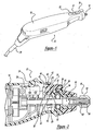
- the rotary tool 10 includes a housing 12 which houses a motor 14.
- the motor 14 is coupled with an output shaft 16.
- the output shaft 16 has a collet 18 on its end to receive rotary tool bits.
- a power source in this view a cord 20, is coupled with the motor 14 to energize the motor.
- An on/off switch 22 is electrically coupled with the motor 14 and the power cord 20 to energize the motor 14.
- the on/off switch 22 includes a sliding member 24 which activates a push button switch 26 which is electrically coupled with the motor 14 and power source 20.
- a shaft locking member, here rotary member 30, is coupled with the housing 12.
- the rotary member 30 has an annular body 32 with an aperture 34 which is received on a pivot pin 36 of the housing 12.
- the rotary member 30 includes a first projecting member 38.
- the projecting member 38 enables the user to grab it and rotate the rotary member 30 about the pivot 36.
- the annular body 32 includes a second projecting member 40 which has an overall tooth shape.
- a third projecting member 42 includes a cantilevered portion 44 which defines a receiving portion, in this example, cut-out 46 which receives a portion of the sliding on/off switch 24.
- the on/off switch 24 can be slid into the cut-out 46 to energize the power tool. After use, the on/off switch 24 is slid out of the cut-out 46. When the on/off switch 24 is in the cut-out 46, the rotating member 30 cannot be rotated and is locked in position when the power tool is energized.
- the annular body 32 includes a pair of detents 50 and 52.
- the detents 50 and 52 receive the head 54 of a spring member 56 which positively holds the rotary member 30 in its engaged and disengaged positions.
- the head 54 is ordinarily a cap which is connected to a spring 56.
- the spring 56 and cap 54 are seated in a channel 58 in the housing 12.
- the cap 54 cams along the body surface 32 until the spring 56 biases the cap 54 into the second detent 52.
- the rotary member 30 is held in its second or engaged position.
- a gear 60 is secured onto the output shaft 16.
- the gear 60 includes a plurality of teeth 62 positioned about its annular body.
- the gear 60 is fixed onto the output shaft 16 so that when the tooth projection 40 engages the gear 60 as illustrated in Figure 3, the output shaft 16 is prohibited from rotating.
- the projecting member 38 is rotated until it is substantially perpendicular to the axis of the tool. In this position, the tooth projection 40 meshes between a pair of teeth 62 on gear 60.
- the output shaft 16 is prohibited from rotating.
- the cap 54 of the spring mechanism 56 engages detent 52 as illustrated in Figure 3.
- the rotating member 30 is held in position by the spring mechanism frictionally biasing in the detent 52.
- the sliding switch 24 cannot be moved forward to energize the motor.
- the power tool is locked in an off position when the rotary member 30 engages the gear 60.
- the projecting member 38 may include a rubber boot 64 to enhance the feel for the user to move it between the engaged and disengaged position.
- the first projection 38 is rotated clockwise until it is substantially parallel with the central axis of the power tool. At this time, the on/off switch 24 can be slid forward to be received within the cut-out 46.
- the tool may be removed from the collet 18 when the output shaft 16 is prohibited from rotating as illustrated in Figure 3.
- the tooth projection engages the gear teeth 62 which, in turn, enables the collet nut 64 to be rotated.
- the collet nut 64 As the collet nut 64 is rotated, it releases the grasping force on the collet fingers 66 of the collet 68.
- the collet fingers 66 expand, the tool may be removed.
- the collet nut 64 is tightened which, in turn, exerts a grasping force on the collet fingers 66 to retain the tool in the collet 68.
- Figures 5 and 6 an additional embodiment of the present invention is shown.
- the embodiment of Figures 5 and 6 are similar to that of Figures 3 and 4 with the same elements having the same identification numerals.
- the difference between the figures is the gear 60'.
- the gear 60' includes teeth 62' which include an angled surface 72'. The angled surfaces act as cam surfaces to engage the tooth 40 of the rotary member 30.
- the gear 60' includes one tooth 74' which has an angled surface 76'. When viewed in elevation, tooth 74' is axially longer on the gear 60' than the other teeth 62' as seen in Figure 5.
- the tooth 74', with its angled surface 76' would be the first tooth to contact the tooth 40 of the rotary member 30 as the tooth 40 attempts to mesh with gear 60' during rotation of the shaft 16 as the shaft 16 winds down.
- the spindle 16 continues to rotate. As the spindle continues to rotate, the gear 60' continues to rotate. If the rotary member 30 attempts to be engaged during this rotation, the tooth 40 contacts the teeth 62' and 74'. Since the tooth 74' is longer than the other teeth 62', the tooth 74' contacts the tooth 40 at a regular duration as the gear and spindle continue to rotate and slow down. The long tooth 74' contacts the tooth 40 of the rotary member 30 with a strong force, giving a positive feedback to the user that the lever cannot be engaged. The single long tooth enables one tooth to contact the tooth 40 of the rotary member 30 during a single rotation instead of each tooth 62' contacting the tooth 40.
- each tooth would produce a rapid contacting of the tooth 40 and not a solid impact which occurs by the single tooth 74'.
- the strong kickout force indicates to the user that the spindle lock is not ready to be engaged since the spindle has not stopped its rotation.
Landscapes
- Engineering & Computer Science (AREA)
- Mechanical Engineering (AREA)
- Drilling And Boring (AREA)
- Forklifts And Lifting Vehicles (AREA)
- Connection Of Motors, Electrical Generators, Mechanical Devices, And The Like (AREA)
- Load-Engaging Elements For Cranes (AREA)
- Devices For Conveying Motion By Means Of Endless Flexible Members (AREA)
- Portable Power Tools In General (AREA)
- Replacement Of Web Rolls (AREA)
- Transmission Devices (AREA)
- Lock And Its Accessories (AREA)
Claims (11)
- Outil électrique comprenant :■ un boîtier (12) ;■ un moteur (14) dans ledit boîtier ;■ un arbre de sortie (16) couplé audit moteur ;■ une source d'énergie couplée audit moteur ;■ un commutateur marche/arrêt (22), comprenant un élément coulissant (24), couplé à ladite source d'énergie et audit moteur pour alimenter et éteindre ledit moteur qui est, alternativement, en mode d'alimentation, ledit moteur fait pivoter ledit arbre de sortie ;■ un élément de rotation (30) adapté pour pouvoir pivoter autour d'un pivot (36) dans ledit boîtier et■ un engrenage (60) avec une ou plusieurs dents (62) fixées sur ledit arbre de sortie dudit outil électrique ;dans lequel ledit élément de rotation comporte un premier élément faisant saillie (38) pour faire pivoter ledit élément de rotation autour dudit pivot (36), et un deuxième élément faisant saillie (40) pour engrener ledit engrenage (60) ; ledit premier élément faisant saillie (38) fait pivoter ledit élément de rotation (30) entre une position engrenée, où ledit deuxième élément faisant saillie engrène ledit engrenage interdisant la rotation dudit arbre (16) et une position désengagée, où ledit deuxième élément faisant saillie (40) désengage ledit engrenage (60), permettant la rotation de l'arbre, caractérisé en ce que ledit élément de rotation (30) comprend une partie de réception (46) pour recevoir ledit élément coulissant (24) dudit commutateur marche/arrêt dans lequel, quand l'élément de rotation (30) est dans la position désengagée, l'élément coulissant (24) peut être coulissé dans la partie de réception (46) afin d'alimenter l'outil électrique et l'élément de rotation (30) est verrouillé dans ladite position désengagée et quand ledit élément de rotation (30) est dans ladite position engrenée, ledit commutateur marche/arrêt est désactivé.
- Outil électrique selon la revendication 1, dans lequel ledit élément de rotation (30) comprend au moins un cran (50) associé à un mécanisme de ressort (56) pour tenir ledit élément de rotation (30) dans ladite position engrenée et désengagée.
- Outil électrique selon la revendication 2, dans lequel ledit élément de rotation comprend une paire de crans, un pour tenir dans ladite position engrenée et l'autre cran pour tenir dans ladite position désengagée.
- Outil électrique selon la revendication 1, dans lequel ledit premier élément faisant saillie étant dans une position parallèle par rapport à un axe central dudit outil quand il est dans une position désengagée et dans une position perpendiculaire à l'axe central dans une position engrenée.
- Outil électrique selon l'une quelconque des revendications précédentes, dans lequel ledit élément de rotation comporte un corps de forme annulaire avec une ouverture intérieure pour recevoir ledit pivot.
- Outil électrique selon la revendication 1, dans lequel ledit commutateur marche/arrêt est désactivé quand ledit premier élément faisant saillie est dans ladite position perpendiculaire.
- Outil électrique selon la revendication 1, dans lequel ladite partie de réception comprend un élément en porte-à-faux définissant une découpe pour recevoir ledit commutateur marche/arrêt.
- Outil électrique selon l'une quelconque des revendications précédentes, dans lequel chacune desdites dents comporte une surface de came à angle pour permettre un engrènement dudit deuxième élément faisant saillie.
- Outil électrique selon la revendication 8, dans lequel une desdites dentes fait saillie au-delà de ladite pluralité des dents permettant à ladite dent d'entrer en contact avec ladite deuxième saillie.
- Outil électrique selon l'une quelconque des revendications précédentes, dans lequel ledit engrenage comprend un élément pour entrer en contact avec ledit deuxième élément faisant saillie.
- Outil électrique selon la revendication 10, dans lequel ledit élément de rotation s'étendant au-delà d'une pluralité de dents sur ledit engrenage.
Applications Claiming Priority (2)
| Application Number | Priority Date | Filing Date | Title |
|---|---|---|---|
| US60386900A | 2000-06-23 | 2000-06-23 | |
| US603869 | 2000-06-23 |
Publications (2)
| Publication Number | Publication Date |
|---|---|
| EP1166973A1 EP1166973A1 (fr) | 2002-01-02 |
| EP1166973B1 true EP1166973B1 (fr) | 2007-11-07 |
Family
ID=24417253
Family Applications (1)
| Application Number | Title | Priority Date | Filing Date |
|---|---|---|---|
| EP01305459A Expired - Lifetime EP1166973B1 (fr) | 2000-06-23 | 2001-06-22 | Verouillage de la broche avec un système de levier et pignon |
Country Status (6)
| Country | Link |
|---|---|
| EP (1) | EP1166973B1 (fr) |
| CN (1) | CN1264655C (fr) |
| AT (1) | ATE377484T1 (fr) |
| CA (1) | CA2348985A1 (fr) |
| DE (1) | DE60131220T2 (fr) |
| HK (1) | HK1040663B (fr) |
Cited By (1)
| Publication number | Priority date | Publication date | Assignee | Title |
|---|---|---|---|---|
| US12257735B2 (en) | 2021-12-20 | 2025-03-25 | Techtronic Cordless Gp | Router including cutting depth locking and adjustment mechanism |
Families Citing this family (3)
| Publication number | Priority date | Publication date | Assignee | Title |
|---|---|---|---|---|
| US7980325B2 (en) * | 2004-01-16 | 2011-07-19 | Credo Technology Corporation | Rotating shaft locking mechanism |
| NL1033187C2 (nl) * | 2007-01-08 | 2008-07-09 | Bosch Gmbh Robert | Elektrisch gereedschap, zoals een haakse slijper. |
| KR101124897B1 (ko) * | 2010-06-04 | 2012-03-27 | 주식회사 오스템 | 차량 시트용 라운드 리클라이너 |
Family Cites Families (4)
| Publication number | Priority date | Publication date | Assignee | Title |
|---|---|---|---|---|
| DE4336620C2 (de) * | 1993-10-27 | 1997-07-03 | Fein C & E | Elektrowerkzeug mit einer nur bei ausgeschaltetem Motor betätigbaren Spannvorrichtung |
| DE4344128B4 (de) * | 1993-12-23 | 2008-09-11 | Robert Bosch Gmbh | Elektrische Handwerkzeugmaschine mit einer Spindelarretierung |
| DE4432973B4 (de) * | 1994-09-16 | 2009-10-01 | Robert Bosch Gmbh | Elektrische Handwerkzeugmaschine mit einer Spindelarretierung |
| GB2327054A (en) * | 1997-07-08 | 1999-01-13 | Black & Decker Inc | Shaft locking |
-
2001
- 2001-05-28 CA CA002348985A patent/CA2348985A1/fr not_active Abandoned
- 2001-06-14 CN CNB011212292A patent/CN1264655C/zh not_active Expired - Fee Related
- 2001-06-22 EP EP01305459A patent/EP1166973B1/fr not_active Expired - Lifetime
- 2001-06-22 AT AT01305459T patent/ATE377484T1/de not_active IP Right Cessation
- 2001-06-22 DE DE60131220T patent/DE60131220T2/de not_active Expired - Lifetime
-
2002
- 2002-03-21 HK HK02102150.0A patent/HK1040663B/zh not_active IP Right Cessation
Cited By (1)
| Publication number | Priority date | Publication date | Assignee | Title |
|---|---|---|---|---|
| US12257735B2 (en) | 2021-12-20 | 2025-03-25 | Techtronic Cordless Gp | Router including cutting depth locking and adjustment mechanism |
Also Published As
| Publication number | Publication date |
|---|---|
| DE60131220D1 (de) | 2007-12-20 |
| HK1040663A1 (en) | 2002-06-21 |
| CN1264655C (zh) | 2006-07-19 |
| CA2348985A1 (fr) | 2001-12-23 |
| ATE377484T1 (de) | 2007-11-15 |
| DE60131220T2 (de) | 2008-08-28 |
| CN1332065A (zh) | 2002-01-23 |
| HK1040663B (zh) | 2006-10-13 |
| EP1166973A1 (fr) | 2002-01-02 |
Similar Documents
| Publication | Publication Date | Title |
|---|---|---|
| US4460296A (en) | Keyless chuck gripping device | |
| US6533291B2 (en) | Chuck having quick change mechanism | |
| EP0335593B1 (fr) | Mandrin sans clé pour outil rotatif | |
| EP1627700B1 (fr) | Mandrin sans clé avec verrouillage automatique et manuel | |
| JP3032006B2 (ja) | 電気式の手持ち工作機械、特にアングルグラインダ | |
| US6789447B1 (en) | Reversible ratchet head assembly | |
| US6488451B1 (en) | Drive shaft lock | |
| US6843627B2 (en) | Wrenchless blade clamp assembly | |
| US4358230A (en) | Chuck operating device for hand drill | |
| EP0066710A2 (fr) | Mécanisme de déverrouillage rapide et de verrouillage positif pour l'utilisation dans les clés à douille et dans les outils à moteur et à impact | |
| US6056298A (en) | Chuck lock bit changer | |
| US6241260B1 (en) | Spring-loaded quick clamp chuck | |
| EP1534453B1 (fr) | Mecanisme de mandrin a connexion rapide | |
| GB2381485A (en) | Chuck jaw position indicium | |
| US6988734B2 (en) | Rotating machine, approximately in the form of a hand drill, a percussion drill, a drill hammer or a battery screwdriver | |
| US4456271A (en) | Tool holder with clamped position latch | |
| JPS6411401B2 (fr) | ||
| US4800785A (en) | Dual-drive ratchet wrench | |
| US5197749A (en) | Keyless chucking device | |
| EP0637484B1 (fr) | Clef | |
| EP1166973B1 (fr) | Verouillage de la broche avec un système de levier et pignon | |
| JPH04269106A (ja) | ドリル/たがね装置 | |
| CN101287569A (zh) | 钻机夹具致动器 | |
| JPH04226821A (ja) | ドリルチャック | |
| CN100366398C (zh) | 钻孔和/或锤击工具 |
Legal Events
| Date | Code | Title | Description |
|---|---|---|---|
| PUAI | Public reference made under article 153(3) epc to a published international application that has entered the european phase |
Free format text: ORIGINAL CODE: 0009012 |
|
| AK | Designated contracting states |
Kind code of ref document: A1 Designated state(s): AT BE CH CY DE DK ES FI FR GB GR IE IT LI LU MC NL PT SE TR |
|
| AX | Request for extension of the european patent |
Free format text: AL;LT;LV;MK;RO;SI |
|
| 17P | Request for examination filed |
Effective date: 20020124 |
|
| AKX | Designation fees paid |
Free format text: AT BE CH CY DE DK ES FI FR GB GR IE IT LI LU MC NL PT SE TR |
|
| 17Q | First examination report despatched |
Effective date: 20060824 |
|
| GRAP | Despatch of communication of intention to grant a patent |
Free format text: ORIGINAL CODE: EPIDOSNIGR1 |
|
| GRAS | Grant fee paid |
Free format text: ORIGINAL CODE: EPIDOSNIGR3 |
|
| GRAA | (expected) grant |
Free format text: ORIGINAL CODE: 0009210 |
|
| AK | Designated contracting states |
Kind code of ref document: B1 Designated state(s): AT BE CH CY DE DK ES FI FR GB GR IE IT LI LU MC NL PT SE TR |
|
| REG | Reference to a national code |
Ref country code: GB Ref legal event code: FG4D |
|
| REG | Reference to a national code |
Ref country code: IE Ref legal event code: FG4D |
|
| REG | Reference to a national code |
Ref country code: CH Ref legal event code: EP |
|
| REF | Corresponds to: |
Ref document number: 60131220 Country of ref document: DE Date of ref document: 20071220 Kind code of ref document: P |
|
| PG25 | Lapsed in a contracting state [announced via postgrant information from national office to epo] |
Ref country code: ES Free format text: LAPSE BECAUSE OF FAILURE TO SUBMIT A TRANSLATION OF THE DESCRIPTION OR TO PAY THE FEE WITHIN THE PRESCRIBED TIME-LIMIT Effective date: 20080218 Ref country code: LI Free format text: LAPSE BECAUSE OF FAILURE TO SUBMIT A TRANSLATION OF THE DESCRIPTION OR TO PAY THE FEE WITHIN THE PRESCRIBED TIME-LIMIT Effective date: 20071107 Ref country code: SE Free format text: LAPSE BECAUSE OF FAILURE TO SUBMIT A TRANSLATION OF THE DESCRIPTION OR TO PAY THE FEE WITHIN THE PRESCRIBED TIME-LIMIT Effective date: 20080207 Ref country code: CH Free format text: LAPSE BECAUSE OF FAILURE TO SUBMIT A TRANSLATION OF THE DESCRIPTION OR TO PAY THE FEE WITHIN THE PRESCRIBED TIME-LIMIT Effective date: 20071107 Ref country code: NL Free format text: LAPSE BECAUSE OF FAILURE TO SUBMIT A TRANSLATION OF THE DESCRIPTION OR TO PAY THE FEE WITHIN THE PRESCRIBED TIME-LIMIT Effective date: 20071107 |
|
| NLV1 | Nl: lapsed or annulled due to failure to fulfill the requirements of art. 29p and 29m of the patents act | ||
| REG | Reference to a national code |
Ref country code: CH Ref legal event code: PL |
|
| PG25 | Lapsed in a contracting state [announced via postgrant information from national office to epo] |
Ref country code: AT Free format text: LAPSE BECAUSE OF FAILURE TO SUBMIT A TRANSLATION OF THE DESCRIPTION OR TO PAY THE FEE WITHIN THE PRESCRIBED TIME-LIMIT Effective date: 20071107 |
|
| ET | Fr: translation filed | ||
| PG25 | Lapsed in a contracting state [announced via postgrant information from national office to epo] |
Ref country code: DK Free format text: LAPSE BECAUSE OF FAILURE TO SUBMIT A TRANSLATION OF THE DESCRIPTION OR TO PAY THE FEE WITHIN THE PRESCRIBED TIME-LIMIT Effective date: 20071107 |
|
| PG25 | Lapsed in a contracting state [announced via postgrant information from national office to epo] |
Ref country code: BE Free format text: LAPSE BECAUSE OF FAILURE TO SUBMIT A TRANSLATION OF THE DESCRIPTION OR TO PAY THE FEE WITHIN THE PRESCRIBED TIME-LIMIT Effective date: 20071107 |
|
| PLBE | No opposition filed within time limit |
Free format text: ORIGINAL CODE: 0009261 |
|
| STAA | Information on the status of an ep patent application or granted ep patent |
Free format text: STATUS: NO OPPOSITION FILED WITHIN TIME LIMIT |
|
| PG25 | Lapsed in a contracting state [announced via postgrant information from national office to epo] |
Ref country code: PT Free format text: LAPSE BECAUSE OF FAILURE TO SUBMIT A TRANSLATION OF THE DESCRIPTION OR TO PAY THE FEE WITHIN THE PRESCRIBED TIME-LIMIT Effective date: 20080407 |
|
| 26N | No opposition filed |
Effective date: 20080808 |
|
| PG25 | Lapsed in a contracting state [announced via postgrant information from national office to epo] |
Ref country code: GR Free format text: LAPSE BECAUSE OF FAILURE TO SUBMIT A TRANSLATION OF THE DESCRIPTION OR TO PAY THE FEE WITHIN THE PRESCRIBED TIME-LIMIT Effective date: 20080208 Ref country code: MC Free format text: LAPSE BECAUSE OF NON-PAYMENT OF DUE FEES Effective date: 20080630 |
|
| PG25 | Lapsed in a contracting state [announced via postgrant information from national office to epo] |
Ref country code: FI Free format text: LAPSE BECAUSE OF FAILURE TO SUBMIT A TRANSLATION OF THE DESCRIPTION OR TO PAY THE FEE WITHIN THE PRESCRIBED TIME-LIMIT Effective date: 20071107 |
|
| PG25 | Lapsed in a contracting state [announced via postgrant information from national office to epo] |
Ref country code: IE Free format text: LAPSE BECAUSE OF NON-PAYMENT OF DUE FEES Effective date: 20080623 |
|
| PG25 | Lapsed in a contracting state [announced via postgrant information from national office to epo] |
Ref country code: CY Free format text: LAPSE BECAUSE OF FAILURE TO SUBMIT A TRANSLATION OF THE DESCRIPTION OR TO PAY THE FEE WITHIN THE PRESCRIBED TIME-LIMIT Effective date: 20071107 |
|
| PG25 | Lapsed in a contracting state [announced via postgrant information from national office to epo] |
Ref country code: LU Free format text: LAPSE BECAUSE OF NON-PAYMENT OF DUE FEES Effective date: 20080622 |
|
| PG25 | Lapsed in a contracting state [announced via postgrant information from national office to epo] |
Ref country code: TR Free format text: LAPSE BECAUSE OF FAILURE TO SUBMIT A TRANSLATION OF THE DESCRIPTION OR TO PAY THE FEE WITHIN THE PRESCRIBED TIME-LIMIT Effective date: 20071107 |
|
| PG25 | Lapsed in a contracting state [announced via postgrant information from national office to epo] |
Ref country code: IT Free format text: LAPSE BECAUSE OF NON-PAYMENT OF DUE FEES Effective date: 20080630 |
|
| PGFP | Annual fee paid to national office [announced via postgrant information from national office to epo] |
Ref country code: GB Payment date: 20140627 Year of fee payment: 14 |
|
| PGFP | Annual fee paid to national office [announced via postgrant information from national office to epo] |
Ref country code: DE Payment date: 20140627 Year of fee payment: 14 |
|
| PGFP | Annual fee paid to national office [announced via postgrant information from national office to epo] |
Ref country code: FR Payment date: 20140617 Year of fee payment: 14 |
|
| REG | Reference to a national code |
Ref country code: DE Ref legal event code: R119 Ref document number: 60131220 Country of ref document: DE |
|
| GBPC | Gb: european patent ceased through non-payment of renewal fee |
Effective date: 20150622 |
|
| REG | Reference to a national code |
Ref country code: FR Ref legal event code: ST Effective date: 20160229 |
|
| PG25 | Lapsed in a contracting state [announced via postgrant information from national office to epo] |
Ref country code: DE Free format text: LAPSE BECAUSE OF NON-PAYMENT OF DUE FEES Effective date: 20160101 Ref country code: GB Free format text: LAPSE BECAUSE OF NON-PAYMENT OF DUE FEES Effective date: 20150622 |
|
| PG25 | Lapsed in a contracting state [announced via postgrant information from national office to epo] |
Ref country code: FR Free format text: LAPSE BECAUSE OF NON-PAYMENT OF DUE FEES Effective date: 20150630 |