EP1166983A2 - Verfahren zum Herstellen von keramischen, mit Dekor versehenen Gefäsen - Google Patents
Verfahren zum Herstellen von keramischen, mit Dekor versehenen Gefäsen Download PDFInfo
- Publication number
- EP1166983A2 EP1166983A2 EP00128333A EP00128333A EP1166983A2 EP 1166983 A2 EP1166983 A2 EP 1166983A2 EP 00128333 A EP00128333 A EP 00128333A EP 00128333 A EP00128333 A EP 00128333A EP 1166983 A2 EP1166983 A2 EP 1166983A2
- Authority
- EP
- European Patent Office
- Prior art keywords
- metal mold
- plastic clay
- pressed
- nozzle
- gap
- Prior art date
- Legal status (The legal status is an assumption and is not a legal conclusion. Google has not performed a legal analysis and makes no representation as to the accuracy of the status listed.)
- Granted
Links
Images
Classifications
-
- B—PERFORMING OPERATIONS; TRANSPORTING
- B28—WORKING CEMENT, CLAY, OR STONE
- B28B—SHAPING CLAY OR OTHER CERAMIC COMPOSITIONS; SHAPING SLAG; SHAPING MIXTURES CONTAINING CEMENTITIOUS MATERIAL, e.g. PLASTER
- B28B1/00—Producing shaped prefabricated articles from the material
- B28B1/02—Producing shaped prefabricated articles from the material by turning or jiggering in moulds or moulding surfaces on rotatable supports
-
- B—PERFORMING OPERATIONS; TRANSPORTING
- B28—WORKING CEMENT, CLAY, OR STONE
- B28B—SHAPING CLAY OR OTHER CERAMIC COMPOSITIONS; SHAPING SLAG; SHAPING MIXTURES CONTAINING CEMENTITIOUS MATERIAL, e.g. PLASTER
- B28B1/00—Producing shaped prefabricated articles from the material
- B28B1/008—Producing shaped prefabricated articles from the material made from two or more materials having different characteristics or properties
-
- B—PERFORMING OPERATIONS; TRANSPORTING
- B28—WORKING CEMENT, CLAY, OR STONE
- B28B—SHAPING CLAY OR OTHER CERAMIC COMPOSITIONS; SHAPING SLAG; SHAPING MIXTURES CONTAINING CEMENTITIOUS MATERIAL, e.g. PLASTER
- B28B3/00—Producing shaped articles from the material by using presses; Presses specially adapted therefor
- B28B3/02—Producing shaped articles from the material by using presses; Presses specially adapted therefor wherein a ram exerts pressure on the material in a moulding space; Ram heads of special form
- B28B3/021—Ram heads of special form
-
- B—PERFORMING OPERATIONS; TRANSPORTING
- B28—WORKING CEMENT, CLAY, OR STONE
- B28B—SHAPING CLAY OR OTHER CERAMIC COMPOSITIONS; SHAPING SLAG; SHAPING MIXTURES CONTAINING CEMENTITIOUS MATERIAL, e.g. PLASTER
- B28B7/00—Moulds; Cores; Mandrels
- B28B7/0097—Press moulds; Press-mould and press-ram assemblies
Definitions
- the invention relates to a method for manufacturing of ceramic, decorated vessels and on a device for performing the method.
- the intended for the implementation of the known method Devices usually consist of a fixed Lower part of the metal mold, which can be lifted out Has bottom part, and a rotatable upper part. The top when pressing the clay bit towards the lower part proceed, whereby there is a gap between the upper and Lower part further reduced until a press end position the metal shape is reached. Excess clay material emerges from the gap between the upper and lower part.
- the invention is based on the object a method and a device for producing ceramic, to provide decorated vessels, which can be carried out more economically than the known one and deliver aesthetically pleasing products at the same time.
- the task is solved by a method of manufacturing ceramic, using a Decorated vessels, in which a chunk of plastic Clay mass between a fixed base and one rotating upper part of a metal mold is pressed, wherein the process comprises the successive steps: Arranging the batch of plastic clay on a extractable bottom piece of the metal mold when opened wide Metal mold, moving the metal mold together, during the Moving together before reaching a minimum gap between a decorative suspension in the lower part and the upper part Gap between the lower part and the upper part is injected, Open the metal mold to take out the pressed piece plastic clay, drying and firing the pressed Batzen's plastic clay.
- the inventive method primarily in that while moving the metal mold decorative suspension in the gap between the lower and upper part of the metal mold is sprayed or injected.
- the decorative suspension is preferred immediately before reaching a press end position injected into the metal mold, into one certain, depending on the desired visual impression Time before reaching the press end position.
- the rotation of the metal mold then occurs of the upper part an uneven distribution of the decorative suspension on the surface of the vessel. Because the circumstances when injecting the decorative suspension from the vessel In any case, the vessel basically deviates slightly from one another, there is always a change in each individual vessel Decor manifestations that match the finished vessel give an individual, handmade character.
- the appearance of the decor can be determined by the exact time spraying or injecting the decorative suspension and the amount of decorative suspension can be varied.
- the decorative suspension can be sprayed through a nozzle where the amount of time the nozzle is open is the amount the injected decorative suspension determined.
- the geometry the opening of the nozzle is also reflected in the appearance of the finished, decorated vessel. Therefore, by varying the opening geometry of the nozzle Influenced the final appearance of the vessel become.
- a device for pressing a lump plastic clay with a metal shape that is a fixed Lower part with removable base and a rotating one Has upper part, means for driving the upper part towards the lower part, so that the lump is more plastic Clay mass is pressed, immediately at a height above the edge of the lower part and to the side of the metal mold a sprayer is arranged, the opening of which is trained and arranged that they suspension suspension through a gap between the lower part and the upper part of the metal mold can inject.
- the spray device can be in the form of a nozzle, which has a Solenoid valve that can be controlled from the outside is opened and is closed.
- the decorative suspension can be a mixture of different, fine ground mineral substances, clay or glaze slip in water, oil or other suitable liquids.
- concentration and composition of the decorative suspension can according to the desired surface effects for the finished Vessels can be adjusted.
- the decorative liquid can be taken up in a storage vessel be, with an agitator settling the solid particles which can prevent decorative liquid.
- a pump can do that Transport decorative suspension to the spraying or spraying device.
- Means can also be provided to determine the geometry of the Vary the opening of the nozzle.
- a change in the nozzle geometry can cause the spray cone between one compact jet and finely divided fog can.
- the nozzle can preferably be at a distance of 10 - 15 cm from the upper edge of the lower part of the metal mold be located away.
- the jet of decorative liquid ejects preferably a control device which has a measuring device which emits a signal indicating reaching a predetermined position of the upper part relative to Reproduces the lower part of the metal mold.
- the measuring device can be formed by an angle encoder, the relative Location of the upper part to the lower part indicates and when reached the desired gap size a pulse to the nozzle emits to eject the decorative liquid jet. This The length of the pulse can be adjusted, making the Set the total amount of decorative liquid to be ejected becomes.
- the diameter of the Decisive nozzle is preferably larger than 1 mm.
- satisfactory Results can be applied in terms of application the decorative liquid with a nozzle that has a diameter of 1.5 mm.
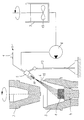
- the figure is a schematic representation of a device for pressing a piece of plastic clay 1.
- a Metal mold consisting of an upper part 2, a lower part 3 and a removable base 4.
- the rotating top 2 in the direction of Move the fixed lower part 3.
- Shortly before reaching the End position for the upper part 2 is by means of a nozzle 5
- Decorative suspension 6 in the gap between the upper part 2 and lower part 3 sprayed.
- the decorative suspension 6 is accommodated in a storage vessel 7 and is conveyed to the nozzle 5 via a pump 8.
- an agitator 13 is provided which in Case of decorative liquids containing solid particles, an even distribution of the solid particles in the decorative liquid causes, in particular a decrease in Prevents solid particles on the bottom of the storage vessel 7.
- the nozzle 5 is actuated on the basis of an external one Control using an incremental encoder (not shown), which is continuous during a pressing process the relative location of the towards the base 3 moved upper part 2 measures and when the desired one is reached Distance between upper part 2 and lower part 3 Sends signal 9 that actuates the nozzle 5.
- the length of the Signal pulse determines the opening time of the nozzle 5 and thus the total amount of ejected at a given nozzle geometry Decorative liquid per spraying process.
- the size of the opening of the nozzle 5 can be in the embodiment by means of a movably arranged on the nozzle axis Pen 10 can be varied. Means are provided to fix the pin 10 in its desired position.
- the axis of the nozzle 5 is opposite the axis of rotation of the rotating upper part 2 of the metal mold arranged at an angle such that the nozzle 5 ejecting decorative liquid the upper edge 11 of the lower part 3 happened at a short distance and subsequent to the Batches of plastic clay mass 1 hits.
- the angle between the axis of the nozzle 5 and the axis of rotation of the upper part 2 of the Metal form is preferably in the range between 30 ° and 80 °. However, the angle is primarily determined by the relative arrangement of the batch of plastic clay 1 too the upper edge of the lower part 3, so that each preferred Angular positions of the nozzle 5 of the vessel shapes being manufactured depends.
- the metal mold is used to manufacture commercially available Flower pots.
- the angular position of the nozzle 5 can be adjusted, and because of the fact that the nozzle 5 is pivotable a holder 12 is attached. In this way the optimal nozzle position for every desired vessel shape to adjust.
Landscapes
- Engineering & Computer Science (AREA)
- Manufacturing & Machinery (AREA)
- Chemical & Material Sciences (AREA)
- Ceramic Engineering (AREA)
- Mechanical Engineering (AREA)
- Press-Shaping Or Shaping Using Conveyers (AREA)
- Devices For Post-Treatments, Processing, Supply, Discharge, And Other Processes (AREA)
- Preparation Of Clay, And Manufacture Of Mixtures Containing Clay Or Cement (AREA)
Abstract
- Anordnen des Batzens der plastischen Tonmasse (1) auf einem aushebbaren Bodenstück (4) der Metallform bei weit geöffneter Metallform,
- Zusammenfahren der Metallform, wobei während des Zusammenfahrens, vor Erreichen eines Mindestspaltes zwischen dem Unterteil (3) und dem Oberteil (2) eine Dekorsuspension in den Spalt zwischen Unterteil und Oberteil eingespritzt wird,
- Öffnen der Metallform zur Herausnahme des gepressten Batzens plastischer Tonmasse (1) und
- Trocknen und Brennen des gepressten Batzens (1) plastischer Tonmasse sowie
Description
Claims (7)
- Verfahren zum Herstellen von keramischen, mit einem Dekor versehenen Gefäßen, bei dem ein Batzen plastischer Tonmasse (1) zwischen einem feststehenden Unterteil (3) und einem rotierenden Oberteil (2) einer Metallform gepresst wird, wobei das Verfahren die aufeinanderfolgenden Schritte umfaßt:Anordnen des Batzens der plastischen Tonmasse (1) auf einem aushebbaren Bodenstück (4) der Metallform bei weit geöffneter Metallform,Zusammenfahren der Metallform, wobei während des Zusammenfahrens, vor Erreichen eines Mindestspaltes zwischen dem Unterteil (3) und dem Oberteil (2) eine Dekorsuspension in den Spalt zwischen Unterteil und Oberteil eingespritzt wird,Öffnen der Metallform zur Herausnahme des gepressten Batzens plastischer Tonmasse (1) undTrocknen und Brennen des gepressten Batzens (1) plastischer Tonmasse.
- Verfahren nach Anspruch 1, bei dem die Dekorsuspension unmittelbar vor Erreichen der Preß-Endstellung der Metallform eingespritzt wird.
- Vorrichtung zum Pressen eines Batzens plastischer Tonmasse, mitdadurch gekennzeichnet, daßeiner Metallform, die ein feststehendes Unterteil (3) mit aushebbarem Bodenstück (4) und ein rotierbares Oberteil (2) aufweist,Mitteln zum Fahren des Oberteils (2) in Richtung des Unterteils (3), so daß der Batzen plastischer Tonmasse (1) gepreßt wird,in einer Höhe unmittelbar oberhalb des Randes des Unterteils (3) und seitlich der Metallform eine Spritzeinrichtung (5) angeordnet ist, deren Öffnung so ausgebildet und angeordnet ist, daß sie Dekorsuspension durch einen Spalt zwischen Unterteil (3) und Oberteil (2) der Metallform spritzen kann.
- Vorrichtung nach Anspruch 3, dadurch gekennzeichnet, daß die Düse (5) eine Öffnung mit kreisförmigem Querschnitt aufweist.
- Vorrichtung nach Anspruch 3 oder 4, dadurch gekennzeichnet, daß die Düse (5) in einem Abstand von 10 bis 15 cm vom oberen Rand des Unterteils (3) der Metallform angeordnet ist.
- Vorrichtung nach einem der Ansprüche 3 bis 5, dadurch gekennzeichnet, daß eine Steuervorrichtung vorgesehen ist, die eine Meßeinrichtung umfaßt, die ein Signal (9) ausgibt, das das Erreichen einer vorbestimmten Lage des Oberteils (2) relativ zum Unterteil (3) der Metallform wiedergibt.
- Vorrichtung nach Anspruch 6, dadurch gekennzeichnet, daß für die Meßeinrichtung ein Winkelkodierer eingesetzt wird.
Applications Claiming Priority (2)
| Application Number | Priority Date | Filing Date | Title |
|---|---|---|---|
| DE20010645 | 2000-06-21 | ||
| DE20010645U | 2000-06-21 |
Publications (3)
| Publication Number | Publication Date |
|---|---|
| EP1166983A2 true EP1166983A2 (de) | 2002-01-02 |
| EP1166983A3 EP1166983A3 (de) | 2003-05-07 |
| EP1166983B1 EP1166983B1 (de) | 2006-03-08 |
Family
ID=7942877
Family Applications (1)
| Application Number | Title | Priority Date | Filing Date |
|---|---|---|---|
| EP00128333A Expired - Lifetime EP1166983B1 (de) | 2000-06-21 | 2000-12-22 | Verfahren zum Herstellen von keramischen, mit Dekor versehenen Gefässen und Vorrichtung zur Durchführung des Verfahrens |
Country Status (3)
| Country | Link |
|---|---|
| EP (1) | EP1166983B1 (de) |
| AT (1) | ATE319544T1 (de) |
| DE (1) | DE50012358D1 (de) |
Cited By (4)
| Publication number | Priority date | Publication date | Assignee | Title |
|---|---|---|---|---|
| DE102007016341A1 (de) * | 2007-04-03 | 2008-10-16 | Gerhart, Edith | Verfahren und Vorrichtung zur Herstellung eines mit einem Dekoreffekt versehenen Gefäßes |
| WO2013011530A1 (en) | 2011-07-18 | 2013-01-24 | Polistampa Linea Decalco Srl | Materials and process for making decalcomanias |
| BE1024415B1 (nl) * | 2016-07-01 | 2018-02-12 | Wienerberger Nv | Inrichting en werkwijze voor het kleuren van een handvormsteen |
| EP3647008A1 (de) * | 2018-10-31 | 2020-05-06 | Westerwälder Blumentopf-Fabrik Spang GmbH & Co. KG | Verfahren zur herstellung eines topfes aus keramik |
Families Citing this family (1)
| Publication number | Priority date | Publication date | Assignee | Title |
|---|---|---|---|---|
| DE102007049326A1 (de) | 2007-10-12 | 2009-04-23 | Gerhart, Edith | Vorrichtung und Verfahren zum Aufbringen einer Dekoration auf einen im Querschnitt runden oder ovalen Gegenstand |
Family Cites Families (3)
| Publication number | Priority date | Publication date | Assignee | Title |
|---|---|---|---|---|
| US2166057A (en) * | 1936-10-16 | 1939-07-11 | Keller Whilldin Pottery Compan | Knock-out |
| GB938901A (en) * | 1961-06-08 | 1963-10-09 | Edgar Gregson | Improvements in tiles for floor covering |
| DE4012700A1 (de) * | 1990-04-20 | 1991-10-31 | Hutschenreuther | Verfahren zur herstellung eines keramischen formkoerpers und einrichtung zum pressen eines keramischen formlings |
-
2000
- 2000-12-22 AT AT00128333T patent/ATE319544T1/de not_active IP Right Cessation
- 2000-12-22 DE DE50012358T patent/DE50012358D1/de not_active Expired - Lifetime
- 2000-12-22 EP EP00128333A patent/EP1166983B1/de not_active Expired - Lifetime
Cited By (6)
| Publication number | Priority date | Publication date | Assignee | Title |
|---|---|---|---|---|
| DE102007016341A1 (de) * | 2007-04-03 | 2008-10-16 | Gerhart, Edith | Verfahren und Vorrichtung zur Herstellung eines mit einem Dekoreffekt versehenen Gefäßes |
| DE102007016341B4 (de) * | 2007-04-03 | 2014-02-27 | Edith Gerhart | Verfahren und Vorrichtung zur Herstellung eines mit einem Dekoreffekt versehenen Gefäßes |
| WO2013011530A1 (en) | 2011-07-18 | 2013-01-24 | Polistampa Linea Decalco Srl | Materials and process for making decalcomanias |
| BE1024415B1 (nl) * | 2016-07-01 | 2018-02-12 | Wienerberger Nv | Inrichting en werkwijze voor het kleuren van een handvormsteen |
| GB2553209B (en) * | 2016-07-01 | 2022-03-09 | Wienerberger Nv | Device and method for colouring a hand-moulded brick |
| EP3647008A1 (de) * | 2018-10-31 | 2020-05-06 | Westerwälder Blumentopf-Fabrik Spang GmbH & Co. KG | Verfahren zur herstellung eines topfes aus keramik |
Also Published As
| Publication number | Publication date |
|---|---|
| DE50012358D1 (de) | 2006-05-04 |
| ATE319544T1 (de) | 2006-03-15 |
| EP1166983B1 (de) | 2006-03-08 |
| EP1166983A3 (de) | 2003-05-07 |
Similar Documents
| Publication | Publication Date | Title |
|---|---|---|
| EP0024608B1 (de) | Verfahren und Einrichtung zum Herstellen von Formteilen aus einem Massiv- oder Schaumstoff bildenden, fliessfähigen Reaktionsgemisch | |
| EP2755806B1 (de) | Verfahren zur herstellung eines betonteiles in 3d-drucktechnik | |
| EP0084672A2 (de) | Vorrichtung zum Erzeugen eines vorzugsweise chemisch reaktionsfähigen Gemisches aus mindestens zwei Kunststoffkomponenten | |
| EP1166983B1 (de) | Verfahren zum Herstellen von keramischen, mit Dekor versehenen Gefässen und Vorrichtung zur Durchführung des Verfahrens | |
| DE1948999C3 (de) | Vorrichtung zum Herstellen von massiven oder geschäumten Formteilen aus schnell miteinander reagierenden chemischen Komponenten | |
| DE2413357C2 (de) | Mischvorrichtung zum Herstellen von Mehrkomponenten-Kunststoffen | |
| DE885152C (de) | Verfahren und Maschine zum Pressen oder Spritzen von mehrfarbigen Teilen, vorzugsweise aus thermoplastischen Kunststoffen | |
| DE69414342T2 (de) | Vorrichtung und Verfahren zum Formen von Gegenständen aus Verbundmaterialien | |
| DE102006059051A1 (de) | Vorrichtung und Verfahren zum Einarbeiten von Flüssigkeit in schütt- oder rieselfähige Trockenstoffe | |
| EP0088936B1 (de) | Mischkopf zum Erzeugen eines vorzugsweise chemisch reaktionsfähigen Gemisches aus mindestens zwei Kunststoffkomponenten | |
| DE2759856C2 (de) | Kosmetikstift und Verfahren zu seiner Herstellung | |
| DE4228749C1 (en) | Boxless moulding machine - has a mist of release and lubricating agent sprayed against plates with compressed air before sand is shot in | |
| DE102007016341B4 (de) | Verfahren und Vorrichtung zur Herstellung eines mit einem Dekoreffekt versehenen Gefäßes | |
| DE10059220C2 (de) | Verfahren und Vorrichtung zur Herstellung von Formkörpern aus Papierrohmasse oder dergleichen | |
| DE19722612C1 (de) | Vorrichtung zum Spritzgießen eines Werkstückes aus mindestens zwei unterschiedlichen Materialkomponenten | |
| DE819217C (de) | Speisewalze fuer Walzapparate zur Flaechenbearbeitung | |
| DE19720304C1 (de) | Verfahren zur Herstellung von Sandformen in Kastenformmaschinen | |
| DE1909536C3 (de) | Vorrichtung zum Gießen eines chemisch reaktionsfähigen Kunststoflf-Komponentengemisches | |
| DE2843799C2 (de) | Verfahren zum Dekorieren von Speiseeis an einem Stiel und Vorrichtung zur Durchführung des Verfahrens | |
| DE102005037451B4 (de) | Verfahren und Vorrichtung zur Herstellung eines wenigstens zwei Komponenten enthaltenden stiftförmigen kosmetischen Produkts, wie Lippenpflegestift oder dergleichen | |
| DE1809933A1 (de) | Verfahren und Vorrichtung zum maschinellen Formen von Steinen | |
| DE461223C (de) | Verfahren und Vorrichtung zur Herstellung von Formsteinen durch Einspritzen des Formguts in eine sich drehende Form | |
| DE681230C (de) | Verfahren und Vorrichtung zum Herstellen von nur einseitig offenen Glashohlkoerpern | |
| DE708404C (de) | Vorrichtung zum Herstellen von keramischen Hohlkoerpern | |
| DE3517691C2 (de) | Verfahren und Vorrichtung zum Herstellen eines metallischen Blockes |
Legal Events
| Date | Code | Title | Description |
|---|---|---|---|
| PUAI | Public reference made under article 153(3) epc to a published international application that has entered the european phase |
Free format text: ORIGINAL CODE: 0009012 |
|
| AK | Designated contracting states |
Kind code of ref document: A2 Designated state(s): AT BE CH CY DE DK ES FI FR GB GR IE IT LI LU MC NL PT SE TR |
|
| AX | Request for extension of the european patent |
Free format text: AL;LT;LV;MK;RO;SI |
|
| PUAL | Search report despatched |
Free format text: ORIGINAL CODE: 0009013 |
|
| AK | Designated contracting states |
Designated state(s): AT BE CH CY DE DK ES FI FR GB GR IE IT LI LU MC NL PT SE TR |
|
| AX | Request for extension of the european patent |
Extension state: AL LT LV MK RO SI |
|
| 17P | Request for examination filed |
Effective date: 20031028 |
|
| AKX | Designation fees paid |
Designated state(s): AT BE CH CY DE DK ES FI FR GB GR IE IT LI LU MC NL PT SE TR |
|
| RTI1 | Title (correction) |
Free format text: METHOD FOR PRODUCING CERAMIC VESSELS WHICH HAVE A DECORATIVE PRINT AND DEVICE FOR CARRYING OUT THE METHOD |
|
| GRAP | Despatch of communication of intention to grant a patent |
Free format text: ORIGINAL CODE: EPIDOSNIGR1 |
|
| GRAS | Grant fee paid |
Free format text: ORIGINAL CODE: EPIDOSNIGR3 |
|
| GRAA | (expected) grant |
Free format text: ORIGINAL CODE: 0009210 |
|
| AK | Designated contracting states |
Kind code of ref document: B1 Designated state(s): AT BE CH CY DE DK ES FI FR GB GR IE IT LI LU MC NL PT SE TR |
|
| PG25 | Lapsed in a contracting state [announced via postgrant information from national office to epo] |
Ref country code: IE Free format text: LAPSE BECAUSE OF FAILURE TO SUBMIT A TRANSLATION OF THE DESCRIPTION OR TO PAY THE FEE WITHIN THE PRESCRIBED TIME-LIMIT Effective date: 20060308 Ref country code: GB Free format text: LAPSE BECAUSE OF FAILURE TO SUBMIT A TRANSLATION OF THE DESCRIPTION OR TO PAY THE FEE WITHIN THE PRESCRIBED TIME-LIMIT Effective date: 20060308 Ref country code: NL Free format text: LAPSE BECAUSE OF FAILURE TO SUBMIT A TRANSLATION OF THE DESCRIPTION OR TO PAY THE FEE WITHIN THE PRESCRIBED TIME-LIMIT Effective date: 20060308 Ref country code: FI Free format text: LAPSE BECAUSE OF FAILURE TO SUBMIT A TRANSLATION OF THE DESCRIPTION OR TO PAY THE FEE WITHIN THE PRESCRIBED TIME-LIMIT Effective date: 20060308 |
|
| REG | Reference to a national code |
Ref country code: GB Ref legal event code: FG4D Free format text: NOT ENGLISH |
|
| REG | Reference to a national code |
Ref country code: CH Ref legal event code: EP |
|
| REG | Reference to a national code |
Ref country code: IE Ref legal event code: FG4D Free format text: LANGUAGE OF EP DOCUMENT: GERMAN |
|
| REF | Corresponds to: |
Ref document number: 50012358 Country of ref document: DE Date of ref document: 20060504 Kind code of ref document: P |
|
| PG25 | Lapsed in a contracting state [announced via postgrant information from national office to epo] |
Ref country code: SE Free format text: LAPSE BECAUSE OF FAILURE TO SUBMIT A TRANSLATION OF THE DESCRIPTION OR TO PAY THE FEE WITHIN THE PRESCRIBED TIME-LIMIT Effective date: 20060608 Ref country code: DK Free format text: LAPSE BECAUSE OF FAILURE TO SUBMIT A TRANSLATION OF THE DESCRIPTION OR TO PAY THE FEE WITHIN THE PRESCRIBED TIME-LIMIT Effective date: 20060608 |
|
| PG25 | Lapsed in a contracting state [announced via postgrant information from national office to epo] |
Ref country code: ES Free format text: LAPSE BECAUSE OF FAILURE TO SUBMIT A TRANSLATION OF THE DESCRIPTION OR TO PAY THE FEE WITHIN THE PRESCRIBED TIME-LIMIT Effective date: 20060619 |
|
| PG25 | Lapsed in a contracting state [announced via postgrant information from national office to epo] |
Ref country code: PT Free format text: LAPSE BECAUSE OF FAILURE TO SUBMIT A TRANSLATION OF THE DESCRIPTION OR TO PAY THE FEE WITHIN THE PRESCRIBED TIME-LIMIT Effective date: 20060808 |
|
| NLV1 | Nl: lapsed or annulled due to failure to fulfill the requirements of art. 29p and 29m of the patents act | ||
| ET | Fr: translation filed | ||
| GBV | Gb: ep patent (uk) treated as always having been void in accordance with gb section 77(7)/1977 [no translation filed] |
Effective date: 20060308 |
|
| REG | Reference to a national code |
Ref country code: IE Ref legal event code: FD4D |
|
| PG25 | Lapsed in a contracting state [announced via postgrant information from national office to epo] |
Ref country code: BE Free format text: LAPSE BECAUSE OF NON-PAYMENT OF DUE FEES Effective date: 20061231 Ref country code: CH Free format text: LAPSE BECAUSE OF NON-PAYMENT OF DUE FEES Effective date: 20061231 Ref country code: MC Free format text: LAPSE BECAUSE OF NON-PAYMENT OF DUE FEES Effective date: 20061231 Ref country code: LI Free format text: LAPSE BECAUSE OF NON-PAYMENT OF DUE FEES Effective date: 20061231 |
|
| PLBE | No opposition filed within time limit |
Free format text: ORIGINAL CODE: 0009261 |
|
| STAA | Information on the status of an ep patent application or granted ep patent |
Free format text: STATUS: NO OPPOSITION FILED WITHIN TIME LIMIT |
|
| 26N | No opposition filed |
Effective date: 20061211 |
|
| REG | Reference to a national code |
Ref country code: CH Ref legal event code: PL |
|
| BERE | Be: lapsed |
Owner name: WESTERWALDER BLUMENTOPFFABRIK SPANG G.M.B.H. & CO. Effective date: 20061231 |
|
| PG25 | Lapsed in a contracting state [announced via postgrant information from national office to epo] |
Ref country code: AT Free format text: LAPSE BECAUSE OF NON-PAYMENT OF DUE FEES Effective date: 20061222 |
|
| PG25 | Lapsed in a contracting state [announced via postgrant information from national office to epo] |
Ref country code: GR Free format text: LAPSE BECAUSE OF FAILURE TO SUBMIT A TRANSLATION OF THE DESCRIPTION OR TO PAY THE FEE WITHIN THE PRESCRIBED TIME-LIMIT Effective date: 20060609 |
|
| PG25 | Lapsed in a contracting state [announced via postgrant information from national office to epo] |
Ref country code: LU Free format text: LAPSE BECAUSE OF NON-PAYMENT OF DUE FEES Effective date: 20061222 Ref country code: TR Free format text: LAPSE BECAUSE OF FAILURE TO SUBMIT A TRANSLATION OF THE DESCRIPTION OR TO PAY THE FEE WITHIN THE PRESCRIBED TIME-LIMIT Effective date: 20060308 |
|
| PG25 | Lapsed in a contracting state [announced via postgrant information from national office to epo] |
Ref country code: CY Free format text: LAPSE BECAUSE OF FAILURE TO SUBMIT A TRANSLATION OF THE DESCRIPTION OR TO PAY THE FEE WITHIN THE PRESCRIBED TIME-LIMIT Effective date: 20060308 |
|
| PGFP | Annual fee paid to national office [announced via postgrant information from national office to epo] |
Ref country code: FR Payment date: 20120103 Year of fee payment: 12 |
|
| PGFP | Annual fee paid to national office [announced via postgrant information from national office to epo] |
Ref country code: DE Payment date: 20111228 Year of fee payment: 12 |
|
| PGFP | Annual fee paid to national office [announced via postgrant information from national office to epo] |
Ref country code: IT Payment date: 20111228 Year of fee payment: 12 |
|
| REG | Reference to a national code |
Ref country code: FR Ref legal event code: ST Effective date: 20130830 |
|
| REG | Reference to a national code |
Ref country code: DE Ref legal event code: R119 Ref document number: 50012358 Country of ref document: DE Effective date: 20130702 |
|
| PG25 | Lapsed in a contracting state [announced via postgrant information from national office to epo] |
Ref country code: DE Free format text: LAPSE BECAUSE OF NON-PAYMENT OF DUE FEES Effective date: 20130702 |
|
| PG25 | Lapsed in a contracting state [announced via postgrant information from national office to epo] |
Ref country code: FR Free format text: LAPSE BECAUSE OF NON-PAYMENT OF DUE FEES Effective date: 20130102 |
|
| PG25 | Lapsed in a contracting state [announced via postgrant information from national office to epo] |
Ref country code: IT Free format text: LAPSE BECAUSE OF NON-PAYMENT OF DUE FEES Effective date: 20121222 |