EP1166986A2 - Hochleistungsvorrichtung und Verfahren zum Formen von Verbundkörpern - Google Patents
Hochleistungsvorrichtung und Verfahren zum Formen von Verbundkörpern Download PDFInfo
- Publication number
- EP1166986A2 EP1166986A2 EP01114718A EP01114718A EP1166986A2 EP 1166986 A2 EP1166986 A2 EP 1166986A2 EP 01114718 A EP01114718 A EP 01114718A EP 01114718 A EP01114718 A EP 01114718A EP 1166986 A2 EP1166986 A2 EP 1166986A2
- Authority
- EP
- European Patent Office
- Prior art keywords
- mold
- translatable
- inserts
- molds
- molding
- Prior art date
- Legal status (The legal status is an assumption and is not a legal conclusion. Google has not performed a legal analysis and makes no representation as to the accuracy of the status listed.)
- Withdrawn
Links
- 238000000465 moulding Methods 0.000 title claims abstract description 74
- 238000000034 method Methods 0.000 title claims abstract description 40
- 239000002131 composite material Substances 0.000 title claims abstract description 18
- 239000011347 resin Substances 0.000 claims abstract description 40
- 229920005989 resin Polymers 0.000 claims abstract description 40
- 239000011324 bead Substances 0.000 claims abstract description 12
- 239000012508 resin bead Substances 0.000 claims description 24
- 238000005245 sintering Methods 0.000 claims description 19
- 239000000463 material Substances 0.000 claims description 9
- 239000000126 substance Substances 0.000 claims description 6
- -1 polypropylene Polymers 0.000 claims description 5
- 239000004743 Polypropylene Substances 0.000 claims description 3
- 238000007654 immersion Methods 0.000 claims description 3
- 229920001155 polypropylene Polymers 0.000 claims description 3
- 239000004793 Polystyrene Substances 0.000 claims description 2
- 230000004888 barrier function Effects 0.000 claims description 2
- 229920001577 copolymer Polymers 0.000 claims description 2
- 230000036961 partial effect Effects 0.000 claims description 2
- 229920002223 polystyrene Polymers 0.000 claims description 2
- 239000004698 Polyethylene Substances 0.000 claims 2
- 230000001351 cycling effect Effects 0.000 claims 2
- 239000004033 plastic Substances 0.000 claims 2
- 229920003023 plastic Polymers 0.000 claims 2
- 229920000573 polyethylene Polymers 0.000 claims 2
- 239000004794 expanded polystyrene Substances 0.000 claims 1
- 238000001816 cooling Methods 0.000 description 5
- XLYOFNOQVPJJNP-UHFFFAOYSA-N water Substances O XLYOFNOQVPJJNP-UHFFFAOYSA-N 0.000 description 5
- 230000013011 mating Effects 0.000 description 4
- 238000002347 injection Methods 0.000 description 3
- 239000007924 injection Substances 0.000 description 3
- 238000004873 anchoring Methods 0.000 description 2
- 238000004519 manufacturing process Methods 0.000 description 2
- 230000007246 mechanism Effects 0.000 description 2
- 230000009467 reduction Effects 0.000 description 2
- 230000002860 competitive effect Effects 0.000 description 1
- 239000000498 cooling water Substances 0.000 description 1
- 230000008878 coupling Effects 0.000 description 1
- 238000010168 coupling process Methods 0.000 description 1
- 238000005859 coupling reaction Methods 0.000 description 1
- 230000000670 limiting effect Effects 0.000 description 1
- 230000004048 modification Effects 0.000 description 1
- 238000012986 modification Methods 0.000 description 1
- 229920000642 polymer Polymers 0.000 description 1
- 230000001681 protective effect Effects 0.000 description 1
Images



Classifications
-
- B—PERFORMING OPERATIONS; TRANSPORTING
- B29—WORKING OF PLASTICS; WORKING OF SUBSTANCES IN A PLASTIC STATE IN GENERAL
- B29C—SHAPING OR JOINING OF PLASTICS; SHAPING OF MATERIAL IN A PLASTIC STATE, NOT OTHERWISE PROVIDED FOR; AFTER-TREATMENT OF THE SHAPED PRODUCTS, e.g. REPAIRING
- B29C44/00—Shaping by internal pressure generated in the material, e.g. swelling or foaming ; Producing porous or cellular expanded plastics articles
- B29C44/34—Auxiliary operations
- B29C44/36—Feeding the material to be shaped
- B29C44/38—Feeding the material to be shaped into a closed space, i.e. to make articles of definite length
- B29C44/42—Feeding the material to be shaped into a closed space, i.e. to make articles of definite length using pressure difference, e.g. by injection or by vacuum
- B29C44/428—Mould constructions; Mould supporting equipment
-
- A—HUMAN NECESSITIES
- A42—HEADWEAR
- A42C—MANUFACTURING OR TRIMMING HEAD COVERINGS, e.g. HATS
- A42C2/00—Manufacturing helmets by processes not otherwise provided for
-
- B—PERFORMING OPERATIONS; TRANSPORTING
- B29—WORKING OF PLASTICS; WORKING OF SUBSTANCES IN A PLASTIC STATE IN GENERAL
- B29C—SHAPING OR JOINING OF PLASTICS; SHAPING OF MATERIAL IN A PLASTIC STATE, NOT OTHERWISE PROVIDED FOR; AFTER-TREATMENT OF THE SHAPED PRODUCTS, e.g. REPAIRING
- B29C31/00—Handling, e.g. feeding of the material to be shaped, storage of plastics material before moulding; Automation, i.e. automated handling lines in plastics processing plants, e.g. using manipulators or robots
- B29C31/008—Handling preformed parts, e.g. inserts
-
- B—PERFORMING OPERATIONS; TRANSPORTING
- B29—WORKING OF PLASTICS; WORKING OF SUBSTANCES IN A PLASTIC STATE IN GENERAL
- B29C—SHAPING OR JOINING OF PLASTICS; SHAPING OF MATERIAL IN A PLASTIC STATE, NOT OTHERWISE PROVIDED FOR; AFTER-TREATMENT OF THE SHAPED PRODUCTS, e.g. REPAIRING
- B29C44/00—Shaping by internal pressure generated in the material, e.g. swelling or foaming ; Producing porous or cellular expanded plastics articles
- B29C44/02—Shaping by internal pressure generated in the material, e.g. swelling or foaming ; Producing porous or cellular expanded plastics articles for articles of definite length, i.e. discrete articles
- B29C44/12—Incorporating or moulding on preformed parts, e.g. inserts or reinforcements
-
- B—PERFORMING OPERATIONS; TRANSPORTING
- B29—WORKING OF PLASTICS; WORKING OF SUBSTANCES IN A PLASTIC STATE IN GENERAL
- B29C—SHAPING OR JOINING OF PLASTICS; SHAPING OF MATERIAL IN A PLASTIC STATE, NOT OTHERWISE PROVIDED FOR; AFTER-TREATMENT OF THE SHAPED PRODUCTS, e.g. REPAIRING
- B29C44/00—Shaping by internal pressure generated in the material, e.g. swelling or foaming ; Producing porous or cellular expanded plastics articles
- B29C44/34—Auxiliary operations
- B29C44/36—Feeding the material to be shaped
- B29C44/38—Feeding the material to be shaped into a closed space, i.e. to make articles of definite length
- B29C44/44—Feeding the material to be shaped into a closed space, i.e. to make articles of definite length in solid form
- B29C44/445—Feeding the material to be shaped into a closed space, i.e. to make articles of definite length in solid form in the form of expandable granules, particles or beads
-
- B—PERFORMING OPERATIONS; TRANSPORTING
- B29—WORKING OF PLASTICS; WORKING OF SUBSTANCES IN A PLASTIC STATE IN GENERAL
- B29C—SHAPING OR JOINING OF PLASTICS; SHAPING OF MATERIAL IN A PLASTIC STATE, NOT OTHERWISE PROVIDED FOR; AFTER-TREATMENT OF THE SHAPED PRODUCTS, e.g. REPAIRING
- B29C44/00—Shaping by internal pressure generated in the material, e.g. swelling or foaming ; Producing porous or cellular expanded plastics articles
- B29C44/34—Auxiliary operations
- B29C44/3415—Heating or cooling
- B29C44/3426—Heating by introducing steam in the mould
Definitions
- the present invention relates to a high-productivity apparatus and method for molding composite items.
- These and other composite elements are substantially constituted by a portion made of a sintered expanded resin and by inserts constituted by the same resin in phases other than the expanded one: for example injection-molded rigid inserts or thermoformed films.
- the inserts can also be constituted by materials whose chemical nature is different from that of the expanded resin: the anchoring of these elements to the expanded-resin portion occurs, in this case, by partial immersion of the inserts in said resin or by applying appropriate primers which, upon adding heat and mechanical pressure, tend to make the inserts adhere to the resin.
- ordinary molding apparatuses are substantially composed of two half-molds, one whereof is movable and the other one is fixed, in order to allow to close and open the half-molds; automation is used to place the inserts in one of the two half-molds.
- the half-molds are substantially constituted by a hollow structure or shell composed of a contoured wall which determines the shape of the parts and of walls which have only a structural function.
- the contoured wall has a plurality of holes which allow the passage of vapor and air between the inside of the shell and the molding chamber formed by mating the two half molds.
- the methods commonly used for molding are substantially of two types.
- a first method places the inserts, by means of automatic manipulators, in one of the two half-molds of an apparatus for molding expanded resin, then performs the molding cycle and finally performs a step of unloading the finished parts from the apparatus.
- the molding step is essentially composed of the following sub-steps: injection of the expanded resin beads in the molding chamber formed by the mating of the two half-molds and by the presence of the inserts; sintering of the beads and simultaneous bonding thereof to the inserts by adding steam; cooling, by adding nebulized water on the internal side of the two half-molds.
- the second type of method entails: execution of the step of sintering the expanded resin portion; assembly of the inserts, by means of the automatic manipulators, with the sintered expanded resin portion; step of bonding one another the inserts and the sintered expanded resin portion; and step of unloading the finished parts from the apparatus.
- the bonding step of this second type of method comprises substantially the following sub-steps: addition of steam (which provides the heat required for bonding); and cooling by applying nebulized water on the inner side of the half-molds.
- the inserts are placed by automation and in any case not simultaneously with the molding step.
- one of the greatest drawbacks of the prior art is low productivity, due to the fact that the operations for placing the inserts and for unloading the finished parts are not simultaneous with the molding operation; the steps of insert placement, molding and unloading of the finished parts are in fact performed sequentially, with no possibility of overlap. Each step can begin only after the end of the preceding step.
- the aim of the present invention is to provide a method for molding composite items in which the insert placement step can occur simultaneously with the molding step.
- an object of the present invention is to provide a method for molding composite items which allows a much higher productivity than known types of method.
- Another object of the present invention is to provide a method for molding composite items which allows to mold even parts having a shape which is very complex and/or difficult to handle automatically.
- Another object of the present invention is to provide a method for molding composite items which allows, thanks to the characteristics of the apparatus, manual intervention between cycles or even during a same molding cycle.
- Another object of the present invention is to provide an apparatus for molding composite materials which allows to implement the molding method with high productivity.
- Another object of the present invention is to provide a method and an apparatus for molding composite items which are highly reliable, relatively simple to manufacture, and at competitive costs.
- a method for molding composite items constituted by beads of sintered expanded resin and by inserts, by using a movable half-mold and first and second half-molds which can perform a translational motion at right angles to the direction of motion of said movable half-mold, characterized in that it comprises the steps consisting of: performing the molding operation by means of one of said translatable half-molds mated with said movable half-mold, translating said translatable half-mold from a position for accessing said half-mold to a molding position, simultaneously accessing the other one of said translatable half-molds when the other one of said translatable half-molds is located at the region for access to said translatable half-mold.
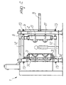
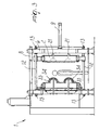
- the apparatus according to the present invention has a molding area or stage 23 and two manual access areas or stages 24 and 25 which are arranged laterally of the molding area 23.
- the presence of operators in these areas is reported by appropriate sensors 26 and 27.
- the control and management system of the apparatus does not enable the movements of the apparatus when the operators are in the manual access areas 24 and 25.
- the apparatus 1 is substantially composed of two uprights 6 and 7, by a cross beam 8 and by columns 12 which are fixed to the uprights 6 and 7 by screw means 13.
- the apparatus 1 further comprises a movable half-mold 2 and two half-molds 3 and 4 which move jointly with each other because they are rigidly coupled to a single movable platform 5. The two movements occur at right angles to each other.
- the half-mold 2 comprises actuation means constituted by cylinders 9 which are rigidly coupled to the upright 6, pistons 10, and stems 11 rigidly coupled to the half-mold 2.
- actuation means constituted by cylinders 9 which are rigidly coupled to the upright 6, pistons 10, and stems 11 rigidly coupled to the half-mold 2.
- the half-mold 2 slides on guiding columns 12.
- the actuation means can be of the electromechanical type, i.e., a system composed of an electric motor, an optional reduction unit and an articulated crank mechanism, or a mixed-type system, composed of a fluid-actuated subsystem and an articulated crank mechanism.
- the half-mold 2 moves between a closure (or active) position, in which it is mated with one of the two translatable half-molds 3 and 4, and an open (or inactive) position, in which the half-mold 2 has moved away at right angles to the direction of motion of the translatable half-molds 3 and 4 so as to allow their disengagement and therefore their movement.
- the platform 5 is provided with actuation means which comprise a cylinder 14, rigidly coupled to the upright 7, a piston 15, and a stem 16, rigidly coupled to the platform 5.
- actuation means which comprise a cylinder 14, rigidly coupled to the upright 7, a piston 15, and a stem 16, rigidly coupled to the platform 5.
- the platform 5 slides on guiding columns 17 being rigidly coupled to the upright 7.
- the actuation means of the platform 5 can be of the electromechanical type, i.e., a system composed of an electric motor, an optional reduction unit, and a toothed pinion, which are rigidly coupled to the platform 5 and a rack rigidly coupled to the upright 7.
- the platform 5 and the half-molds 3 and 4 rigidly coupled thereto move between a position in which the half-mold 3 is in the molding area 23 and the half-mold 4 is in the manual access area 25, and a position in which the half-mold 4 lies in the molding area 23 while the half-mold 3 is in the manual access area 24.
- the half-mold 2 is assumed to be the movable one and the half-molds 3 and 4 are assumed to be the translatable ones.
- the apparatus according to the invention has three systems for feeding beads of expanded resin.
- the composite items to be manufactured with the apparatus according to the invention are made of sintered beads of expanded resin, designated by the reference numerals 31 and 33, and by inserts 32 and 34.
- the inserts 32 and 34 can be made of the same resin that constitutes the expanded beads 31 and 33 in different phases of the expanded material: for example, rigid injection-molded inserts or thermoformed films.
- the inserts 32 and 34 can also be constituted by materials whose chemical nature differs from that of the expanded resin 31 and 33. Anchoring of these elements to the expanded resin portion 31 and 33 occurs therefore by partially immersing the inserts in the resin or by applying appropriate primers which, upon adding heat and mechanical pressure, tend to make the inserts adhere to the resin.
- the inserts 32 and 34 can be constituted by sintered expanded resin beads, of the same chemical nature (same polymers or copolymers having the same base) as the expanded resin base elements 31 and 33 but with different physical and mechanical properties.
- the expanded resin beads 31, 33 are fed by means of a hopper 21 with an injector 21 for the movable half-mold, a hopper 18 with an injector 28 for the translatable half-mold 3, and a hopper 19 with an injector 29 for the translatable half-mold 4.
- the apparatus according to the invention can have systems for feeding the expanded resin beads 31, 33 only for the movable half-mold 2 or only for the translatable half-molds 3 and 4.
- the apparatus further comprises a pump for generating vacuum (not shown) and is provided with couplings for the passage of services required to perform the molding steps: steam service, compressed air service, cooling water service (all of which are not shown).
- the apparatus allows to carry out two different methods.
- a first method performs the cycle with a single molding step: the step of sintering the expanded resin beads 31 and 33 and the step of joining them (by bonding or immersion) with the inserts 32 are simultaneous.
- the movable half-mold 2 is in the open position and one of the two translatable half-molds 3 and 4 is in one of the two manual access positions 24 or 25.
- the translatable half-mold 3 is in the manual access position 24 and therefore the translatable half-mold 4 is in the molding position 23.
- the operator manually places the inserts 32 in the translatable half-mold 3.
- the inserts 32 are fixed by means of interlocks and/or the generation of negative pressure in the shell of the half-mold 3. Then the operator leaves the protection area of the apparatus 22.
- the management and control system of the apparatus receives from the protection sensors 26 the signal that the operator has left the protection area of the apparatus 22 and thus gives the clearance for the translational motion of the translatable platform 5.
- the translatable platform 5 and the half-molds 3 and 4 rigidly coupled thereto perform a translational motion until the half-mold 3 is in the molding position 23 and the half-mold 4 is in the manual access position 25.
- the movable half-mold 2 is moved into the closure position by means of the cylinders 9, the pistons 10, and the piston rods 11.
- the half-mold 2 slides on the guiding columns 12.
- the molding step then begins and consists of the following sub-steps: injection, by means of the injectors 21 and the hopper 20, of the expanded resin beads 31 into the molding chamber formed by the mating of the half-molds 2 and 3 and by the presence of the inserts 32; sintering of the beads 31 and simultaneous bonding thereof to the inserts 32 by adding steam; cooling, by adding nebulized water on the inner side of the half-molds 2 and 3.
- the movable half-mold 2 moves into the open position, Figure 5d, and the manufactured article is extracted onto the translatable half-mold 3.
- the translatable platform 5 and the half-molds 3 and 4 rigidly coupled thereto perform a translational motion until the half-mold 4 is in the molding position 23 and the half-mold 3 is in the manual access position 24.
- the movable half-mold 2 is moved into the position for closure with the translatable half-mold 4, Figure 5d, and the molding step (sintering of the expanded resin beads 31 and their simultaneous bonding to the inserts 32 by adding steam) begins.
- the operator unloads, manually and/or with the aid of mechanical extractors, the finished part from the translatable half-mold 3: then he manually places the inserts 32 in the same translatable half-mold.
- the movable half-mold 2 moves into the open position, Figure 5e, the manufactured article is extracted onto the translatable half-mold 4, and the translatable platform 5 and the half-molds 3 and 4 that are rigidly coupled thereto perform a translational motion until the half-mold 3 is in the molding position 23 and the half-mold 4 is in the manual access position 25.
- the cycle is in the steady state and continues with the steps in which alternately one of the two translatable half-molds is engaged with the movable half-mold 2 in the molding step, while the other translatable half-mold is in position in the respective manual access area (area 24 for the half-mold 3, are 25 for the half-mold 4) and can be accessed for manual and/or mechanical unloading of the finished parts and for the manual placement of the inserts 32.
- the second method that can be implemented with the apparatus according to the invention performs the cycle with a double molding step: the step of sintering the expanded resin beads 33 and the step of bonding them to the inserts 34 are separate.
- the movable half-mold 2 is in the open position.
- One of the two translatable half-molds 3, 4 is in one of the two manual access positions 24 or 25.
- the half-mold 3 is in the manual access position 24. Accordingly, the translatable half-mold 4 is in the molding position 23.
- the movable half-mold 2 is moved into the closure position by means of the cylinders 9, the pistons 10 and the piston rods 11.
- the half-mold 2 slides on the guiding columns 12.
- the step of sintering the expanded resin 33 begins and consists of the following sub-steps: injection, by means of the injectors 29 and the hopper 19, of the expanded resin beads into the molding chamber formed by the mating of the half-molds 2 and 4; sintering of the beads by adding steam; cooling, by adding nebulized water on the internal side of the half-molds.
- the movable half-mold is moved into the position for closure with the translatable half-mold 3 and the step of sintering the expanded resin 33 begins (the resin beads are injected by means of the injectors 28 and the hopper 18).
- the operator manually assembles the inserts 34 with the sintered expanded resin element 32 on the translatable half-mold 4.
- the movable half-mold 2 moves into the open position (the sintered expanded resin element 33 is extracted onto the translatable half-mold 3), and the translatable platform 5 and the half-molds 3 and 4 which are rigidly coupled thereto perform a translational motion until the half-mold 4 is the molding position 23 and the half-mold 3 is in the manual access position 24.
- the movable half-mold 2 is then moved into the position for closure with the translatable half-mold 4, Figure 6f, and the step for bonding the inserts 34 with the sintered expanded resin elements 33 begins.
- This step is composed of the following sub-steps: addition of steam (which provides the heat required for bonding); cooling, by adding nebulized water on the inner side of the half-molds.
- the operator manually assembles the inserts 34 with the sintered expanded resin element 33 on the translatable half-mold 3.
- the movable half-mold 2 moves into the open position, Figure 6g, the finished part is extracted onto the translatable half-mold 4, and the translatable platform 5 and the half-molds 3 and 4 rigidly coupled thereto perform a translational motion until the half-mold 3 is in the molding position 23 and the half-mold 4 is in the manual access position 25.
- the movable half-mold 2 is moved into the position for closure with the translatable half-mold 3 and the step of bonding the inserts 34 with the sintered expanded resin elements 33 begins. Simultaneously with this bonding step, in the manual access position 25, the operator unloads, manually and/or with the aid of mechanical extractors, the finished part from the translatable half-mold 4.
- the movable half-mold 2 moves into the open position, Figure 6i, the manufactured article is extracted onto the translatable half-mold 3, and the translatable platform 5 and the half-molds 3 and 4 rigidly coupled thereto perform a translational motion until the half-mold 4 reaches the molding position 23 and the half-mold 3 reaches the manual access position 24.
- the movable half-mold 2 is moved into the position for closure with the translatable half-mold 4 and the step of sintering the expanded resin 33 begins. Simultaneously with this sintering step, in the manual access position 24, the operator unloads, manually and/or with the aid of mechanical extractors, the finished part from the translatable half-mold 3.
- the cycle is in the steady state and continues with the steps in which alternatively one of the two translatable half-molds is engaged, with the movable half-mold 2, in the step of sintering the expanded resin 33 or in the step of mutually bonding said resin and the inserts 34.
- the other translatable half-mold is in position in the respective manual access area (region 24 for the half-mold 3, region 25 for the half-mold 4) and can be accessed for the manual and/or mechanical unloading of the finished parts and for the manual placement of the inserts 34 (assembly with the sintered expanded resin elements 33).
- the particularity of the apparatus of allowing manual intervention between each cycle or even during each cycle allows to produce composite items even with inserts which have a very complex shape and/or are difficult to handle and would be impossible to produce with known types of apparatus which use mechanical manipulators.
- the materials used may be any according to requirements and to the state of the art.
Landscapes
- Engineering & Computer Science (AREA)
- Manufacturing & Machinery (AREA)
- Mechanical Engineering (AREA)
- Robotics (AREA)
- Processing And Handling Of Plastics And Other Materials For Molding In General (AREA)
- Moulds For Moulding Plastics Or The Like (AREA)
Applications Claiming Priority (2)
| Application Number | Priority Date | Filing Date | Title |
|---|---|---|---|
| ITMI001465 | 2000-06-29 | ||
| IT2000MI001465A IT1318068B1 (it) | 2000-06-29 | 2000-06-29 | Apparecchiatura e procedimento ad elevata produttivita' per lostampaggio di particolari compositi |
Publications (2)
| Publication Number | Publication Date |
|---|---|
| EP1166986A2 true EP1166986A2 (de) | 2002-01-02 |
| EP1166986A3 EP1166986A3 (de) | 2003-03-19 |
Family
ID=11445373
Family Applications (1)
| Application Number | Title | Priority Date | Filing Date |
|---|---|---|---|
| EP01114718A Withdrawn EP1166986A3 (de) | 2000-06-29 | 2001-06-21 | Hochleistungsvorrichtung und Verfahren zum Formen von Verbundkörpern |
Country Status (3)
| Country | Link |
|---|---|
| US (1) | US20020028261A1 (de) |
| EP (1) | EP1166986A3 (de) |
| IT (1) | IT1318068B1 (de) |
Families Citing this family (3)
| Publication number | Priority date | Publication date | Assignee | Title |
|---|---|---|---|---|
| KR100897434B1 (ko) * | 2008-10-15 | 2009-05-25 | 주식회사 나노텍세라믹스 | 경량 헬멧쉘 |
| ITUA20161558A1 (it) * | 2016-03-11 | 2017-09-11 | Alessiohitech S R L | Pressa e procedimento per lo stampaggio di polimeri termoplastici espansi. |
| US12459178B2 (en) * | 2016-07-22 | 2025-11-04 | Crocs, Inc. | Methods and apparatus for injection and manufacture of molded components with vacuum assist |
Family Cites Families (10)
| Publication number | Priority date | Publication date | Assignee | Title |
|---|---|---|---|---|
| US1332963A (en) * | 1917-09-27 | 1920-03-09 | New York Belting & Packing Com | Press for molding plastic articles |
| US2314823A (en) * | 1939-08-10 | 1943-03-23 | Jenkins Bros | Molding apparatus |
| DE2613768C3 (de) * | 1976-03-31 | 1984-09-06 | Fa. Ph. Kurtz, 6981 Hasloch | Vorrichtung zum zweistufigen Herstellen von geschäumten Thermoplast-Erzeugnissen |
| JPS5967008A (ja) * | 1982-10-07 | 1984-04-16 | Sumitomo Chem Co Ltd | 熱可塑性樹脂のプレス成形方法 |
| DE3805558C1 (en) * | 1988-02-23 | 1989-06-29 | Welle Gmbh & Co Kg, 4790 Paderborn, De | Process and apparatus for the foam-filling of furniture decorations |
| US5134259A (en) * | 1990-04-25 | 1992-07-28 | Page Jr Lawrence C | Palm button switch apparatus |
| US5474841A (en) * | 1992-04-23 | 1995-12-12 | Kanegafuchi Kagaku Kogyo Kabushiki Kaisha | Polypropylene resin cellular molded article having a skin and production method therefor |
| FR2710287B1 (fr) * | 1993-09-22 | 1995-12-08 | Daniel Renaudet | Presse de moulage et de collage et procédé de moulage et collage successifs. |
| DE4420510A1 (de) * | 1994-06-13 | 1995-12-14 | Ho Chang Hsien | Helm-Herstellungsverfahren und Vorrichtung dafür |
| CA2351424A1 (en) * | 1998-11-20 | 2000-06-02 | Krauss-Maffei Kunststofftechnik Gmbh | Method of producing injection-molded parts in an injection-molding machine |
-
2000
- 2000-06-29 IT IT2000MI001465A patent/IT1318068B1/it active
-
2001
- 2001-06-21 EP EP01114718A patent/EP1166986A3/de not_active Withdrawn
- 2001-06-22 US US09/886,117 patent/US20020028261A1/en not_active Abandoned
Also Published As
| Publication number | Publication date |
|---|---|
| IT1318068B1 (it) | 2003-07-21 |
| EP1166986A3 (de) | 2003-03-19 |
| ITMI20001465A0 (it) | 2000-06-29 |
| ITMI20001465A1 (it) | 2001-12-29 |
| US20020028261A1 (en) | 2002-03-07 |
Similar Documents
| Publication | Publication Date | Title |
|---|---|---|
| US6210619B1 (en) | Method for manufacturing a two-piece plastic assembly | |
| TW200408525A (en) | Method and apparatus for post mold cooling of plastic pieces | |
| US20150076735A1 (en) | Injection molding machine | |
| EP3500415B1 (de) | Umspritztes vorformsystem und verfahren | |
| US5629031A (en) | Remover for injection-molded article | |
| EP1166986A2 (de) | Hochleistungsvorrichtung und Verfahren zum Formen von Verbundkörpern | |
| EP0773098B1 (de) | Verfahren und Vorrichtung zum einstückigen Formen eines thermoplastischen Laminataufbaus | |
| EP2019744B1 (de) | System zum integrieren eines einsatzes mit einem formkörper | |
| EP1252009B1 (de) | Verfahren und vorrichtung zum spritzgiessen | |
| US20040119205A1 (en) | Rotating turret molding machine and associated process | |
| US7364683B2 (en) | Rotary automatic transfer rail for injection molding | |
| CN218964035U (zh) | 一种磁性材料加工成型模具 | |
| CN101879774A (zh) | 成型控制系统及运用该系统的模内装饰成型方法 | |
| US20050255184A1 (en) | Encased Mold Injection Molding | |
| WO2019083787A2 (en) | INJECTION MOLDING OF PLASTIC AND PROCESSES | |
| WO1993014618A1 (en) | Apparatus for moulding a lead frame and chips arranged thereon | |
| EP2024160A1 (de) | Maschine zum formen von kautschuk und kunststoffen | |
| KR20180032942A (ko) | 사출성형장치와 이를 이용한 사출성형방법 | |
| JP3101571B2 (ja) | 射出成形用金型装置 | |
| CN108349136B (zh) | 注射成型方法 | |
| EP1092525A1 (de) | Spritzgiessformzusammenbau | |
| US20210283808A1 (en) | Multilayer preform injection molding | |
| JPH11147236A (ja) | 表皮材インサート成形の成形条件設定方法および装置 | |
| JPH04339617A (ja) | サンドイッチ成形方法 | |
| JPH0716977B2 (ja) | 表皮付き成形品の成形用金型 |
Legal Events
| Date | Code | Title | Description |
|---|---|---|---|
| PUAI | Public reference made under article 153(3) epc to a published international application that has entered the european phase |
Free format text: ORIGINAL CODE: 0009012 |
|
| AK | Designated contracting states |
Kind code of ref document: A2 Designated state(s): AT BE CH CY DE DK ES FI FR GB GR IE IT LI LU MC NL PT SE TR |
|
| AX | Request for extension of the european patent |
Free format text: AL;LT;LV;MK;RO;SI |
|
| PUAL | Search report despatched |
Free format text: ORIGINAL CODE: 0009013 |
|
| AK | Designated contracting states |
Kind code of ref document: A3 Designated state(s): AT BE CH CY DE DK ES FI FR GB GR IE IT LI LU MC NL PT SE TR Designated state(s): AT BE CH CY DE DK ES FI FR GB GR IE IT LI LU MC NL PT SE TR |
|
| AX | Request for extension of the european patent |
Extension state: AL LT LV MK RO SI |
|
| 17P | Request for examination filed |
Effective date: 20030721 |
|
| AKX | Designation fees paid |
Designated state(s): AT BE CH CY DE DK ES FI FR GB GR IE IT LI LU MC NL PT SE TR |
|
| 17Q | First examination report despatched |
Effective date: 20050623 |
|
| STAA | Information on the status of an ep patent application or granted ep patent |
Free format text: STATUS: THE APPLICATION IS DEEMED TO BE WITHDRAWN |
|
| 18D | Application deemed to be withdrawn |
Effective date: 20060104 |