EP1167043A1 - Netoyage de tête d'impression à jet d'encre - Google Patents
Netoyage de tête d'impression à jet d'encre Download PDFInfo
- Publication number
- EP1167043A1 EP1167043A1 EP01202232A EP01202232A EP1167043A1 EP 1167043 A1 EP1167043 A1 EP 1167043A1 EP 01202232 A EP01202232 A EP 01202232A EP 01202232 A EP01202232 A EP 01202232A EP 1167043 A1 EP1167043 A1 EP 1167043A1
- Authority
- EP
- European Patent Office
- Prior art keywords
- cleaning
- particles
- contaminate
- self
- printer
- Prior art date
- Legal status (The legal status is an assumption and is not a legal conclusion. Google has not performed a legal analysis and makes no representation as to the accuracy of the status listed.)
- Withdrawn
Links
- 238000004140 cleaning Methods 0.000 title claims abstract description 179
- 239000002245 particle Substances 0.000 claims abstract description 86
- 239000007788 liquid Substances 0.000 claims abstract description 78
- 229920000642 polymer Polymers 0.000 claims abstract description 15
- 238000010008 shearing Methods 0.000 claims abstract description 5
- 230000002301 combined effect Effects 0.000 claims abstract description 4
- 239000000356 contaminant Substances 0.000 claims description 40
- 239000004094 surface-active agent Substances 0.000 claims description 8
- 239000002184 metal Substances 0.000 claims description 5
- 229910052751 metal Inorganic materials 0.000 claims description 5
- 125000000524 functional group Chemical group 0.000 claims description 2
- 239000011324 bead Substances 0.000 abstract description 9
- 239000004793 Polystyrene Substances 0.000 abstract description 3
- 229920002223 polystyrene Polymers 0.000 abstract description 3
- 239000007787 solid Substances 0.000 description 15
- 239000012530 fluid Substances 0.000 description 10
- 230000001965 increasing effect Effects 0.000 description 6
- 238000000034 method Methods 0.000 description 6
- 238000007639 printing Methods 0.000 description 4
- -1 silicon oxide Chemical compound 0.000 description 4
- 230000015572 biosynthetic process Effects 0.000 description 3
- MTHSVFCYNBDYFN-UHFFFAOYSA-N diethylene glycol Chemical compound OCCOCCO MTHSVFCYNBDYFN-UHFFFAOYSA-N 0.000 description 3
- 238000013467 fragmentation Methods 0.000 description 3
- 238000006062 fragmentation reaction Methods 0.000 description 3
- 239000000203 mixture Substances 0.000 description 3
- 239000002904 solvent Substances 0.000 description 3
- KFZMGEQAYNKOFK-UHFFFAOYSA-N Isopropanol Chemical compound CC(C)O KFZMGEQAYNKOFK-UHFFFAOYSA-N 0.000 description 2
- 238000004220 aggregation Methods 0.000 description 2
- 230000002776 aggregation Effects 0.000 description 2
- 239000003795 chemical substances by application Substances 0.000 description 2
- 238000004891 communication Methods 0.000 description 2
- 238000009826 distribution Methods 0.000 description 2
- 239000000463 material Substances 0.000 description 2
- 230000007723 transport mechanism Effects 0.000 description 2
- 238000009736 wetting Methods 0.000 description 2
- CHRJZRDFSQHIFI-UHFFFAOYSA-N 1,2-bis(ethenyl)benzene;styrene Chemical compound C=CC1=CC=CC=C1.C=CC1=CC=CC=C1C=C CHRJZRDFSQHIFI-UHFFFAOYSA-N 0.000 description 1
- ISRGONDNXBCDBM-UHFFFAOYSA-N 2-chlorostyrene Chemical compound ClC1=CC=CC=C1C=C ISRGONDNXBCDBM-UHFFFAOYSA-N 0.000 description 1
- VVQNEPGJFQJSBK-UHFFFAOYSA-N Methyl methacrylate Chemical compound COC(=O)C(C)=C VVQNEPGJFQJSBK-UHFFFAOYSA-N 0.000 description 1
- VYPSYNLAJGMNEJ-UHFFFAOYSA-N Silicium dioxide Chemical compound O=[Si]=O VYPSYNLAJGMNEJ-UHFFFAOYSA-N 0.000 description 1
- BQCADISMDOOEFD-UHFFFAOYSA-N Silver Chemical compound [Ag] BQCADISMDOOEFD-UHFFFAOYSA-N 0.000 description 1
- 239000002253 acid Substances 0.000 description 1
- 150000007513 acids Chemical class 0.000 description 1
- 150000001252 acrylic acid derivatives Chemical class 0.000 description 1
- 235000011130 ammonium sulphate Nutrition 0.000 description 1
- 230000003466 anti-cipated effect Effects 0.000 description 1
- 239000002585 base Substances 0.000 description 1
- 230000005540 biological transmission Effects 0.000 description 1
- 230000001680 brushing effect Effects 0.000 description 1
- 150000007942 carboxylates Chemical group 0.000 description 1
- 238000011109 contamination Methods 0.000 description 1
- 229920001577 copolymer Polymers 0.000 description 1
- 229940028356 diethylene glycol monobutyl ether Drugs 0.000 description 1
- 239000000428 dust Substances 0.000 description 1
- 238000007786 electrostatic charging Methods 0.000 description 1
- 230000003028 elevating effect Effects 0.000 description 1
- 238000005516 engineering process Methods 0.000 description 1
- PCHJSUWPFVWCPO-UHFFFAOYSA-N gold Chemical compound [Au] PCHJSUWPFVWCPO-UHFFFAOYSA-N 0.000 description 1
- 239000010931 gold Substances 0.000 description 1
- 229910052737 gold Inorganic materials 0.000 description 1
- 239000012528 membrane Substances 0.000 description 1
- 229910044991 metal oxide Inorganic materials 0.000 description 1
- 150000004706 metal oxides Chemical class 0.000 description 1
- IWVKTOUOPHGZRX-UHFFFAOYSA-N methyl 2-methylprop-2-enoate;2-methylprop-2-enoic acid Chemical compound CC(=C)C(O)=O.COC(=O)C(C)=C IWVKTOUOPHGZRX-UHFFFAOYSA-N 0.000 description 1
- 239000004530 micro-emulsion Substances 0.000 description 1
- TVMXDCGIABBOFY-UHFFFAOYSA-N octane Chemical compound CCCCCCCC TVMXDCGIABBOFY-UHFFFAOYSA-N 0.000 description 1
- JCGNDDUYTRNOFT-UHFFFAOYSA-N oxolane-2,4-dione Chemical compound O=C1COC(=O)C1 JCGNDDUYTRNOFT-UHFFFAOYSA-N 0.000 description 1
- 238000005192 partition Methods 0.000 description 1
- 229920003217 poly(methylsilsesquioxane) Polymers 0.000 description 1
- 229920002451 polyvinyl alcohol Polymers 0.000 description 1
- 235000019422 polyvinyl alcohol Nutrition 0.000 description 1
- 238000005086 pumping Methods 0.000 description 1
- 125000001453 quaternary ammonium group Chemical group 0.000 description 1
- 238000004064 recycling Methods 0.000 description 1
- 230000002441 reversible effect Effects 0.000 description 1
- 229910052814 silicon oxide Inorganic materials 0.000 description 1
- 229910052709 silver Inorganic materials 0.000 description 1
- 239000004332 silver Substances 0.000 description 1
- 238000005507 spraying Methods 0.000 description 1
- 150000003871 sulfonates Chemical class 0.000 description 1
- 238000004506 ultrasonic cleaning Methods 0.000 description 1
- 238000002604 ultrasonography Methods 0.000 description 1
- 150000003673 urethanes Chemical class 0.000 description 1
- XLYOFNOQVPJJNP-UHFFFAOYSA-N water Substances O XLYOFNOQVPJJNP-UHFFFAOYSA-N 0.000 description 1
Images


Classifications
-
- B—PERFORMING OPERATIONS; TRANSPORTING
- B41—PRINTING; LINING MACHINES; TYPEWRITERS; STAMPS
- B41J—TYPEWRITERS; SELECTIVE PRINTING MECHANISMS, i.e. MECHANISMS PRINTING OTHERWISE THAN FROM A FORME; CORRECTION OF TYPOGRAPHICAL ERRORS
- B41J2/00—Typewriters or selective printing mechanisms characterised by the printing or marking process for which they are designed
- B41J2/005—Typewriters or selective printing mechanisms characterised by the printing or marking process for which they are designed characterised by bringing liquid or particles selectively into contact with a printing material
- B41J2/01—Ink jet
- B41J2/135—Nozzles
- B41J2/165—Prevention or detection of nozzle clogging, e.g. cleaning, capping or moistening for nozzles
- B41J2/16517—Cleaning of print head nozzles
- B41J2/16552—Cleaning of print head nozzles using cleaning fluids
-
- B—PERFORMING OPERATIONS; TRANSPORTING
- B41—PRINTING; LINING MACHINES; TYPEWRITERS; STAMPS
- B41J—TYPEWRITERS; SELECTIVE PRINTING MECHANISMS, i.e. MECHANISMS PRINTING OTHERWISE THAN FROM A FORME; CORRECTION OF TYPOGRAPHICAL ERRORS
- B41J2/00—Typewriters or selective printing mechanisms characterised by the printing or marking process for which they are designed
- B41J2/005—Typewriters or selective printing mechanisms characterised by the printing or marking process for which they are designed characterised by bringing liquid or particles selectively into contact with a printing material
- B41J2/01—Ink jet
- B41J2/17—Ink jet characterised by ink handling
- B41J2/18—Ink recirculation systems
- B41J2/185—Ink-collectors; Ink-catchers
Definitions
- This invention generally relates to ink jet printer apparatus and methods and more particularly relates to apparatus and methods for cleaning a print head.
- An ink jet printer produces images on a receiver by ejecting ink droplets onto the receiver in an imagewise fashion.
- So called “continuous” ink jet printers utilize electrostatic charging tunnels that are placed close to the point where ink droplets are being ejected in the form of a stream. Selected ones of the droplets are intercepted downstream, while other droplets are free to strike a recording medium.
- ink droplets are ejected from selected nozzle orifices only when needed.
- the ink jet print head is exposed to the environment at the nozzle orifice opening, which are exposed to many kinds of air born particulates.
- Particulate debris may accumulate on surfaces formed around the orifices and may accumulate in the orifices and ink ejection chambers themselves.
- the ink may combine with such particulate debris to form an interference burr that blocks the orifice or that alters surface wetting to inhibit proper formation of the ink droplet.
- the particulate debris should be cleaned from the surface and orifice to restore proper droplet formation. In the prior art, this cleaning is commonly accomplished by brushing, wiping, spraying, vacuum suction, and/or spitting of ink through the orifice.
- U.S. Patent 4,600,928 by Braun et al., issued July 15, 1986, teaches an ultrasonic self-cleaning system for cleaning of a print head assembly wherein ink is supported in approximation to the orifices of the print head by capillary force. Ultrasonic cleaning pulses are then applied to clean the surface through fluid transmission of that ultrasound energy to said surface.
- a self-cleaning printer includes a print head having a surface that is susceptible to a contaminate build up.
- a cleaning liquid containing a concentration of macroscopic cleaning particles is flowed in frictive contact with the contaminate, during which forces are exerted on the contaminant by contact between the contaminant and at least one cleaning particle and energy is exchanged by contact between the contaminant and the cleaning particle, such that a combined effect of frictive force and the hydrodynamic shearing force of the liquid acting on the contaminate effectively removes the contaminate from the surface.
- the cleaning particles are adapted to attach to the contaminate. They may include polymeric beads such as polystyrene spheres.
- the cleaning particles preferably have surfaces to which polymeric chains are attached, the polymeric chains having end groups which adhere to the contaminate.
- FIGS. 1 and 2 show a self-cleaning printer 10 for printing an image 20 on a receiver 30 supported on a platen roller 40 rotated by a motor 50 to advance the receiver in direction illustrated by first arrow 55.
- a print head 60 comprises a print head body 65 having a plurality of ink channels 70, each terminating in a channel outlet 75. Channels 70 are adapted to hold an ink body 77, and are defined by oppositely disposed parallel side walls 79a and 79b.
- a cover plate 80 has a plurality of orifices 90 formed there through to colinearly align with respective ones of channel outlets 75, such that each orifice 90 faces receiver 30.
- a surface 85 of cover plate 80 surrounds all orifices 90 and also faces receiver 30.
- the printer may be of drop on demand or continuous technology. In any case, ink droplets 105 are preferably ejected along a first axis 107 normal to surface 85.
- a transport mechanism 110 reciprocates print head 60 between a first position 115a (shown in phantom) and a second position 115b along an elongate guide rail 120 parallel to platen roller 40.
- Transport mechanism 110 includes a drive belt 130 attached to print head 60.
- a reversible motor 140 engages belt 130, such that belt 130 reciprocates.
- An encoder strip 150 coupled to print head 60 monitors the position of the print head along guide rail 120.
- a controller 160 is connected to platen roller motor 50, drive belt motor 140, encoder strip 150 and print head 60 for controlling operation thereof to suitably form image 20 on receiver 30.
- cover plate 80 may become contaminated by contaminate 165 which will reside on surface 85.
- contaminate may partially or completely obstruct orifice 90.
- Contaminate 165 may be, for example, particles of dirt, dust, metal and/or encrustations of dried ink. Presence of contaminate 165 may fully or partially obstruct orifice 90 to prevent ink from being ejected or divert the droplets from first axis 107, causing them to travel along a second axis 167. If ink droplet 105 travels along second axis 167, the droplet will land on receiver 30 in an unintended location.
- a cleaning assembly 170 is disposed proximate surface 85 for directing a flow of cleaning liquid along surface 85 and across orifice 90 to clean contaminate 165 therefrom while print head 60 is disposed at second position 115b.
- Cleaning assembly 170 includes a housing 180 with a cup 190 having an open end 195 and defining a cavity 197 communicating with open end 195. Attached to open end 195 is an elastomeric seal 200 encircling one or more orifices 90 and sealingly engaging surface 85.
- a structural member such as an elongate septum 210, extends along cavity 197 perpendicularly opposite orifices 90.
- Septum 210 has an end portion 215 which defines a gap 220 defined between surface 85 and end portion 215.
- Gap 220 is sized to allow flow of a liquid there through in order to clean contaminate 165 from surface 85 and/or orifice 90.
- the velocity of the liquid through gap 220 may be about 1 to 20 meters per second.
- height of gap 220 may be approximately 3 to 30 thousandths of an inch with a preferred gap height of approximately 5 to 20 thousandths of an inch.
- septum 210 may be approximately 1 to 30 psi (pounds per square inch).
- Septum 210 partitions (i.e., divides) cavity 197 into an inlet chamber 230 and an outlet chamber 240, for reasons described more fully hereinbelow.
- a septum is preferred to enhance the flow rate of liquids in the vicinity of orifices 90, its use is not required in the practice of the current invention, since other means of increasing the rate of flow of the cleaning liquid exist, for example the rate may be increased by increasing the fluid pressure at the inlet 230.
- the cleaning liquid may be any suitable liquid solvent composition, such as water, isopropanol, diethylene glycol, diethylene glycol monobutyl ether, octane, acids and bases, surfactant solutions and a combination thereof.
- suitable liquid solvent compositions such as water, isopropanol, diethylene glycol, diethylene glycol monobutyl ether, octane, acids and bases, surfactant solutions and a combination thereof.
- Complex liquid compositions may also be used, such as microemulsions, micellar surfactant solutions, vesicles and solid particles dispersed in the liquid.
- the cleaning liquid carries a high concentration of macroscopic cleaning particles 395 which are described below with respect to FIGS. 10 and 11.
- a closed-loop piping circuit 250 interconnects inlet chamber 230 and outlet chamber 240. Piping circuit 250 is in fluid communication with gap 220 for recycling liquid through gap 220. Piping circuit 250 includes a first piping segment 260 extending from outlet chamber 240 to a reservoir 270 containing a supply of the liquid. Piping circuit 250 further includes a second piping segment 280 extending from reservoir 270 to inlet chamber 230. A recirculation pump 290 is disposed in second piping segment 280 for pumping the liquid from reservoir 270, through second piping segment 280, into inlet chamber 230, through gap 220, into outlet chamber 240, through first piping segment 260 and back to reservoir 270, as illustrated by a plurality of second arrows 295.
- a first valve 320 in first piping segment 260 is operable to block flow of the liquid through first piping segment 260.
- a second valve 330 in second piping segment 280 is operable to block flow of the liquid through second piping segment 280.
- First valve 320 and second valve 330 are located so as to isolate cavity 197 from reservoir 270.
- a third piping segment 340 has an open end thereof connected to first piping segment 260 and another open end thereof received into a sump 350. In communication with sump 350 is a suction (i.e., vacuum) pump 360.
- a third valve 370 operable to isolate piping circuit 250 from sump 350 is disposed in third piping segment 340.
- first valve 320 and second valve 310 are opened while third valve 370 is closed.
- Recirculation pump 290 is then operated to draw the liquid from reservoir 270 and into inlet chamber 230.
- the liquid will then flows through gap 220.
- a hydrodynamic shearing force will be induced in the liquid due to presence of end portion 215 of septum 210 and macroscopic cleaning particles 395 are carried into frictive contact with contaminate 165.
- Contact with the contaminants removes most contaminants by physically dislodging them. If the cleaning particles bond, either momentarily or permanently, to the contaminants, the flow of the rest of the cleaning solution exerts a force on the cleaning particle that is transmitted to the contaminant and helps dislodge it.
- the contaminant is dislodged, it is swept away in the flow of cleaning fluid, whether or not it is bonded to the cleaning particles. If the contaminants are only weakly lodged on the printhead surfaces or if the size of the cleaning particles is sufficiently large, use of septum 210 is not required in the practice of the current invention.
- the combined effect of the frictive force and the hydrodynamic shearing force acting on contaminate 165 effectively removes contaminate 165 from surface 85 and/or orifice 90, so that contaminate 165 becomes entrained in the liquid flowing through gap 220.
- frictive contact is achieved with both surface 85 and the inner surfaces of orifice 90.
- the cleaning liquid preferably carries away both the cleaning particles and the contaminants on the print head. As contaminate 165 is cleaned from surface 85 and orifice 90, the liquid with contaminate 165 entrained therein, flows into outlet chamber 240 and from there into first piping segment 260.
- recirculation pump 290 continues to operate, the liquid with entrained contaminate 165 flows to reservoir 270 from where the liquid is pumped into second piping segment 280.
- recirculation pump 290 is caused to cease operation and first valve 320 and second valve 330 are closed to isolate cavity 197 from reservoir 270.
- third valve 370 is opened and suction pump 360 is operated to substantially suction the liquid from first piping segment 260, second piping segment 280 and cavity 197. This suctioned liquid flows into sump 350 for later disposal.
- a fluid having no solid cleaning particles can be circulated over gap 220, for example by exchanging reservoir 270 for one containing a fluid having no cleaning particles in order to flush out all contaminants and cleaning particles from the region around gap 220 and from the associated piping 260, 280.
- an elevator 380 may be connected to cleaning assembly 170 for elevating cleaning assembly 170 so that seal 200 sealingly engages surface 85 when print head 60 is at second position 115b.
- elevator 380 is connected to controller 160, so that operation of elevator 380 is controlled by controller 160.
- elevator 380 may be lowered so that seal no longer engages surface 85.
- Previously-discussed embodiments of the present invention deal with apparatus and process for external cleaning of a print head.
- the following embodiments related to internal cleaning of the nozzle bores, including the region where cleaning liquid drops are expelled through the nozzles, and to a combination of simultaneous external cleaning and internal cleaning.
- FIGS. 6a, 6b, and 6c show an inkjet print head 400 of the continuous type in top view, side view and end view, respectively.
- the print head has a plurality of nozzles 402 formed in a membrane 404 in contact with an ink cavity 406.
- the ink cavity has an inlet port 408 and an outlet port 410, each with a valve 412 and 414, respectively, as shown in FIG. 7a.
- inlet port valve 412 is turned so as to interconnect inlet port 408 with a pressurized ink supply 416.
- outlet port valve 414 is normally closed, although in some cases, when additional ink for the nozzles is desired, the outlet port valve may be set to connect outlet port 410 to pressurized ink supply 416.
- inlet port valve 412 is set to connect inlet port 408 with a pressurized cleaning liquid supply 418. If it is desired to clean internal ink cavity 406, the outlet port valve 414 is set to connect outlet port 410 to a removal port 420, such as a port having a vacuum or partial vacuum, so as to draw the cleaning liquid along the print head cavity as shown in FIGS. 7b and 7c. If the cleaning liquid pressure is sufficiently low, surface tension of the cleaning liquid may prevent the cleaning liquid from flowing out nozzles 402.
- the cleaning liquid pressure is made sufficiently large by reducing the degree of vacuum in a removal port 420, for example, or by setting outlet port valve 414 during cleaning to connect outlet port 410 to pressurized cleaning liquid supply 418, then some or all of the cleaning liquid will exit the cavity through nozzles 402 as illustrated in FIG. 7d.
- the liquid passing though the nozzles will thereby cleaning the nozzle bore regions.
- the expelled cleaning liquid may be captured in a receiver cup 422 or upon a print receiver 424 in regions where no image is to be printed, as illustrated in FIGS. 7e and 7f).
- the receiver may in this case be positioned sufficiently close to the nozzles that expelled cleaning liquid contacts the receiver before breaking into discreet drops, as in FIG.
- the print head be moved over the receiver so as to prevent the cleaning liquid from building up.
- the solid cleaning particles may be chosen to be of a large size, for example at least twice as large in diameter as the diameter of the nozzle, so that particles do not pass through nozzles 402.
- a print head is shown having a septum 426 between inlet port 408 and outlet port 410.
- septum 426 causes hydrodynamic shear in the vicinity of the back of nozzles. Such shear enhances cleaning by increasing the liquid velocity in region immediately below the bottom of the septum.
- FIG. 9 shows a combination of internal and external cleaning.
- Cleaning liquid is circulated in ink cavity 406 of print head 400 via inlet port 408 and outlet port 410.
- Cleaning liquid is also circulated over external surfaces of nozzles 402 on the side opposite ink cavity 406 by a cleaning assembly 170 of the type shown in FIGS. 4 and 5.
- a cleaning assembly 170 of the type shown in FIGS. 4 and 5.
- it is also additionally possible to clean the inner surfaces of the nozzle bores by forcing liquid from cleaning assembly 170 into ink cavity 406 by sufficient pressure in the cleaning chamber, or conversely.
- FIGS. 10a and 10b are expanded views of a pair of cleaning particles 395 and 395', respectively.
- Each particle is a bead 430 which may contain surfactants (functionalized surface elements) attached to a portion of the bead and extending from its surface.
- Beads 430 may be made of polymer such as polystyrene, methylmethacrylate and divinylbenzne, or copolymer such as styrenedivinylbenzene, methylmethacrylate-methacrylic acid, quaternernized vinyl chlorobenzene, and polymethylsilsesquioxane.
- bead 430 may be made of metal such as gold or silver, metal oxides such as silicon oxide, and metal carbonates. Beads 430 are preferably larger than about 1 micron and contain no materials, such as ink, that might tend to be themselves contaminates.
- the solid particles contain functionalized surface elements 432 comprising polymer chains attached at one end to the beads such that the functionalized surface elements can bond to contaminants.
- the functionalized surface elements of FIG. 10a may be of the type which bond chemically to any number of contaminants or groups of contaminants or to specific contaminants (such as acrylates, polyvinyl alcohols, siloxanes and urethanes) or of the type which bonds electrostatically (such as carboxylate groups, quaternary ammonium sulfates and sulfonates, pyridinium ions, etc.).
- Polymer beads may be infused with surfactants carrying the desired functional groups.
- the functionalized surface elements of FIG. 10b include elements of both types.
- each particle contain only a single type of functionalized surface element but that the cleaning solution contain particles some of which have different functionalized surface elements than others. It may also be desirable to employ functionalized surface elements which attach directly to ink molecules, since contaminants may be assumed likely to contain ink molecules. Also, because the forces exerted by the flow of the cleaning liquid on the solid cleaning particles in general depends on the size of the cleaning particles and because the forces required to dislodge contaminants may in general vary from one region of contamination to another, it is in some cases preferred that the solid cleaning particles have a distribution of sizes.
- the degree of rotational motion of particles in a flowing liquid depends on the shape of the particles and since the rotation of cleaning particles may assist dislodging them, it is in some cases preferred that the solid cleaning particles have a distribution of shapes, specifically, some being elongated.
- the cleaning solution may also be desirable in certain cases that the cleaning particles be of only one type, for example if it is known that the primary contaminants are of a single type. Similarly, if the primary contaminants are known to be of only a few types, it is preferred that two or more different cleaning solutions be passed sequentially through the regions to be cleaned, each cleaning liquid having cleaning particles of only one type, designed in conjunction with the liquid solvent portion of the cleaning liquid so as to maximize the cleaning of a particular contaminant. In these cases, additional reservoirs and valves are required to change cleaning solutions, as would be appreciated by one skilled in the art of fluid control.
- the cleaning liquid be pumped at a constant rate, usually a large rate, in order to subject contaminants to a large, constant frictive force from contact with solid cleaning particles in the cleaning liquid
- a higher flow rate is then useful in order to subject contaminants to a large frictive force.
- the slow rate is preferably at least a factor of two slower than the fast rate. More than two rates of flow may also be useful in optimizing cleaning for cases in which a range of contaminants is anticipated.
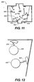
- FIG. 11 shows a case similar to that of FIG. 10 but for a more complex sequence of cleaning operations.
- polymers 434 having functionalized surface groups at opposed ends are dispersed in a cleaning liquid containing no solid cleaning particles.
- One end, an "A" site is chosen so as to attach to the contaminants and the other end, a "B" site is chosen so as to attach to the surface of solid cleaning particles 436 (FIG. 12) later introduced.
- a cleaning liquid having polymers 434 with functionalized surface groups "A" and "B” but having initially no solid cleaning particles is introduced to the print head in a manner similar to that used in the cases of the cleaning liquids discussed previously.
- a more complex sequence of cleaning operations involves flowing a second cleaning liquid through or about the printhead surfaces, after the first cleaning liquid has been and flushed.
- the cleaning particles in the second cleaning liquid are designed to adhere primarily to the cleaning particles of the first cleaning liquid.
- functionalized surface elements attached to the second cleaning particles may be designed to have their free ends attach only to particular functionalized surface elements deliberately placed on the first cleaning particles. In this way a number of second cleaning particles may become attached to any remaining first cleaning particles which may be attached to contaminants not dislodged and flushed away or to any remaining first cleaning particles which themselves have become lodged on the printhead surfaces even in the absence of contaminants, thereby increasing the effective forces which the flow of cleaning liquid applies to remaining first cleaning particles.
- an agent in the cleaning solution such as a dispersive agent, commonly used to prevent aggregation may be removed or deactivated, thereby allowing controlled aggregation of the remaining cleaning particles to occur.
Landscapes
- Ink Jet (AREA)
Applications Claiming Priority (4)
| Application Number | Priority Date | Filing Date | Title |
|---|---|---|---|
| US59947200A | 2000-06-22 | 2000-06-22 | |
| US599472 | 2000-06-22 | ||
| US09/641,107 US6517188B1 (en) | 2000-06-22 | 2000-08-17 | Ink jet print head cleaning |
| US641107 | 2000-08-17 |
Publications (1)
| Publication Number | Publication Date |
|---|---|
| EP1167043A1 true EP1167043A1 (fr) | 2002-01-02 |
Family
ID=27083352
Family Applications (1)
| Application Number | Title | Priority Date | Filing Date |
|---|---|---|---|
| EP01202232A Withdrawn EP1167043A1 (fr) | 2000-06-22 | 2001-06-11 | Netoyage de tête d'impression à jet d'encre |
Country Status (2)
| Country | Link |
|---|---|
| US (1) | US6517188B1 (fr) |
| EP (1) | EP1167043A1 (fr) |
Cited By (8)
| Publication number | Priority date | Publication date | Assignee | Title |
|---|---|---|---|---|
| US6517188B1 (en) * | 2000-06-22 | 2003-02-11 | Eastman Kodak Company | Ink jet print head cleaning |
| EP1375156A1 (fr) * | 2002-06-28 | 2004-01-02 | Agfa-Gevaert | Méthode pour nettoyer la plaque à buses |
| EP1621348A1 (fr) * | 2004-07-22 | 2006-02-01 | Toshiba Tec Kabushiki Kaisha | Solution de lavage pour une tête imprimante à jet d'encre et procédé de lavage utilisant la solution |
| US7108367B2 (en) | 2002-04-24 | 2006-09-19 | Toshiba Tec Kabushiki Kaisha | Liquid ink and recording apparatus |
| US7118189B2 (en) | 2004-05-28 | 2006-10-10 | Videojet Technologies Inc. | Autopurge printing system |
| US7285581B2 (en) | 2003-06-18 | 2007-10-23 | Toshiba Tec Kabushiki Kaisha | Processed pigments, pigment-dispersed solution, ink for ink jet, manufacturing method of processed pigments and manufacturing method of pigment-dispersed solution |
| US7375145B2 (en) | 2003-10-28 | 2008-05-20 | Toshiba Tec Kabushiki Kaisha | Inkjet ink |
| US7439281B2 (en) | 2003-10-28 | 2008-10-21 | Toshiba Tec Kabushiki Kaisha | Pigment dispersion, precursor of ink for UV-curing type ink-jet recording, method of ink-jet recording, printed matter, and method of manufacturing pigment dispersion |
Families Citing this family (6)
| Publication number | Priority date | Publication date | Assignee | Title |
|---|---|---|---|---|
| US7331664B2 (en) * | 2004-10-29 | 2008-02-19 | Hewlett-Packard Development Company, L.P. | Ink delivery system and a method for replacing ink |
| JP4864617B2 (ja) * | 2006-09-21 | 2012-02-01 | 株式会社東芝 | 洗浄液及びノズルプレート洗浄方法 |
| CN110337361B (zh) * | 2017-01-31 | 2022-04-15 | 惠普发展公司,有限责任合伙企业 | 打印头清洁系统 |
| WO2018143228A1 (fr) * | 2017-02-01 | 2018-08-09 | 東レエンジニアリング株式会社 | Dispositif et procédé de nettoyage de tête à jet d'encre |
| CN107696702A (zh) * | 2017-10-28 | 2018-02-16 | 青岛三皆益喷码技术有限公司 | 一种用于喷码机的内外部自动清洗装置 |
| CN115648485B (zh) * | 2022-12-27 | 2023-04-11 | 金发科技股份有限公司 | 一种塑料制品回收清洗设备及其清洗方法 |
Citations (5)
| Publication number | Priority date | Publication date | Assignee | Title |
|---|---|---|---|---|
| JPH04146997A (ja) * | 1990-10-08 | 1992-05-20 | General Kk | サーマルヘッドクリーニング剤 |
| US5688060A (en) * | 1995-04-25 | 1997-11-18 | Alps Electric Co., Ltd. | Thermal transfer printer |
| JPH11152499A (ja) * | 1997-11-21 | 1999-06-08 | Fuji Xerox Co Ltd | インクジェットヘッド洗浄液およびその製造方法ならびにそれを用いたインクジェットヘッドの洗浄方法 |
| JPH11334091A (ja) * | 1998-05-22 | 1999-12-07 | Brother Ind Ltd | インクジェットヘッドの洗浄方法及びその装置 |
| EP1005997A1 (fr) * | 1998-12-04 | 2000-06-07 | Eastman Kodak Company | Imprimante à jet d'encre auto-nettoyante à écoulement inverse et procédé d'assemblage de l'imprimante |
Family Cites Families (4)
| Publication number | Priority date | Publication date | Assignee | Title |
|---|---|---|---|---|
| US6010683A (en) * | 1997-11-05 | 2000-01-04 | Ultradent Products, Inc. | Compositions and methods for reducing the quantity but not the concentration of active ingredients delivered by a dentifrice |
| JP2000311877A (ja) * | 1999-04-26 | 2000-11-07 | Nippon Electric Glass Co Ltd | 板状体の洗浄方法及び洗浄装置 |
| US6196657B1 (en) * | 1999-06-16 | 2001-03-06 | Eastman Kodak Company | Multi-fluidic cleaning for ink jet print heads |
| US6517188B1 (en) * | 2000-06-22 | 2003-02-11 | Eastman Kodak Company | Ink jet print head cleaning |
-
2000
- 2000-08-17 US US09/641,107 patent/US6517188B1/en not_active Expired - Fee Related
-
2001
- 2001-06-11 EP EP01202232A patent/EP1167043A1/fr not_active Withdrawn
Patent Citations (5)
| Publication number | Priority date | Publication date | Assignee | Title |
|---|---|---|---|---|
| JPH04146997A (ja) * | 1990-10-08 | 1992-05-20 | General Kk | サーマルヘッドクリーニング剤 |
| US5688060A (en) * | 1995-04-25 | 1997-11-18 | Alps Electric Co., Ltd. | Thermal transfer printer |
| JPH11152499A (ja) * | 1997-11-21 | 1999-06-08 | Fuji Xerox Co Ltd | インクジェットヘッド洗浄液およびその製造方法ならびにそれを用いたインクジェットヘッドの洗浄方法 |
| JPH11334091A (ja) * | 1998-05-22 | 1999-12-07 | Brother Ind Ltd | インクジェットヘッドの洗浄方法及びその装置 |
| EP1005997A1 (fr) * | 1998-12-04 | 2000-06-07 | Eastman Kodak Company | Imprimante à jet d'encre auto-nettoyante à écoulement inverse et procédé d'assemblage de l'imprimante |
Non-Patent Citations (3)
| Title |
|---|
| PATENT ABSTRACTS OF JAPAN vol. 016, no. 431 (C - 0983) 9 September 1992 (1992-09-09) * |
| PATENT ABSTRACTS OF JAPAN vol. 1999, no. 11 30 September 1999 (1999-09-30) * |
| PATENT ABSTRACTS OF JAPAN vol. 2000, no. 03 30 March 2000 (2000-03-30) * |
Cited By (15)
| Publication number | Priority date | Publication date | Assignee | Title |
|---|---|---|---|---|
| US6517188B1 (en) * | 2000-06-22 | 2003-02-11 | Eastman Kodak Company | Ink jet print head cleaning |
| US7500745B2 (en) | 2002-04-24 | 2009-03-10 | Toshiba Tec Kabushiki Kaisha | Liquid ink and recording apparatus |
| US7108367B2 (en) | 2002-04-24 | 2006-09-19 | Toshiba Tec Kabushiki Kaisha | Liquid ink and recording apparatus |
| US7387380B2 (en) | 2002-04-24 | 2008-06-17 | Toshiba Tec Kabushiki Kaisha | Liquid ink and recording apparatus |
| US7125112B2 (en) | 2002-04-24 | 2006-10-24 | Toshiba Tec Kabushiki Kaisha | Liquid ink and recording apparatus |
| EP1375156A1 (fr) * | 2002-06-28 | 2004-01-02 | Agfa-Gevaert | Méthode pour nettoyer la plaque à buses |
| US7285581B2 (en) | 2003-06-18 | 2007-10-23 | Toshiba Tec Kabushiki Kaisha | Processed pigments, pigment-dispersed solution, ink for ink jet, manufacturing method of processed pigments and manufacturing method of pigment-dispersed solution |
| US7375145B2 (en) | 2003-10-28 | 2008-05-20 | Toshiba Tec Kabushiki Kaisha | Inkjet ink |
| US7439281B2 (en) | 2003-10-28 | 2008-10-21 | Toshiba Tec Kabushiki Kaisha | Pigment dispersion, precursor of ink for UV-curing type ink-jet recording, method of ink-jet recording, printed matter, and method of manufacturing pigment dispersion |
| US7473720B2 (en) | 2003-10-28 | 2009-01-06 | Toshiba Tec Kabushiki Kaisha | Photosensitive inkjet ink |
| US7754785B2 (en) | 2003-10-28 | 2010-07-13 | Toshiba Tec Kabushiki Kaisha | Pigment dispersion, precursor of ink for UV-curing type ink-jet recording, method of ink-jet recording, printed matter, and method of manufacturing pigment dispersion |
| US7118189B2 (en) | 2004-05-28 | 2006-10-10 | Videojet Technologies Inc. | Autopurge printing system |
| CN100404261C (zh) * | 2004-07-22 | 2008-07-23 | 东芝泰格有限公司 | 喷墨打印机打印头用清洁溶液及使用该溶液的清洗方法 |
| US7425525B2 (en) | 2004-07-22 | 2008-09-16 | Toshiba Tec Kabushiki Kaisha | Washing solution for inkjet printer head and washing method using the solution |
| EP1621348A1 (fr) * | 2004-07-22 | 2006-02-01 | Toshiba Tec Kabushiki Kaisha | Solution de lavage pour une tête imprimante à jet d'encre et procédé de lavage utilisant la solution |
Also Published As
| Publication number | Publication date |
|---|---|
| US6517188B1 (en) | 2003-02-11 |
Similar Documents
| Publication | Publication Date | Title |
|---|---|---|
| US6517188B1 (en) | Ink jet print head cleaning | |
| EP1005997B1 (fr) | Imprimante à jet d'encre auto-nettoyante à écoulement inverse et procédé d'assemblage de l'imprimante | |
| EP1060894B1 (fr) | Nettoyage à plusieurs fluides pour têtes d'impression à jet d'encre | |
| US6183058B1 (en) | Self-cleaning ink jet printer system with reverse fluid flow and method of assembling the printer system | |
| EP1088665B1 (fr) | Système d'imprimante à jet d'encre auto-nettoyant à écoulement de fluide réversible et à rouleau tournant, et méthode d'assemblage du système d'imprimante | |
| EP1170130B1 (fr) | Ensemble pour nettoyer une tête d'impression à jet d'encre dans un système d'impression à jet d'encre auto-nettoyant | |
| US20020085059A1 (en) | Ink jet print head with capillary flow cleaning | |
| US10730305B2 (en) | Inkjet printing system with non-contact cleaning station | |
| JP4403379B2 (ja) | インクジェットプリンタ用ヘッド清掃装置及び該清掃装置を備えたプリンタ | |
| EP0995606A2 (fr) | Imprimante à jet d'encre auto-nettoyante au moyen d'ultrasons et procédé pour son assemblage | |
| JP2000190514A (ja) | インクジェットプリンタ―およびその組立方法 | |
| JP2000198214A (ja) | 洗浄機構付きインクジェットプリンタ及びその組立て方法 | |
| JP2001038925A (ja) | インクジェット式記録装置および同装置におけるクリーニング制御方法 | |
| US6145952A (en) | Self-cleaning ink jet printer and method of assembling same | |
| EP1005998A1 (fr) | Imprimante à jet d'encre auto-nettoyante à écoulement de fluide inversible et à ultrasons, et procédé d'assemblage de l'imprimante | |
| JP2000229416A (ja) | 振動隔壁及び超音波のある自己洗浄型インクジェットプリンターとそのプリンターの組立方法 | |
| US8100517B2 (en) | Printer with foaming system for cleaning ejecting face | |
| JP2000280488A (ja) | インクジェット式記録装置のフラッシング方法及びインクジェット式記録装置 | |
| US7922285B2 (en) | Method of cleaning a printhead using liquid foam | |
| US8382234B2 (en) | Printhead maintenance system for applying foam to printhead | |
| JP4645172B2 (ja) | インクジェット記録装置及び記録ヘッドのクリーニング方法 | |
| JP3480683B2 (ja) | インクジェット式記録装置 | |
| JP6915707B2 (ja) | 液体噴射装置 |
Legal Events
| Date | Code | Title | Description |
|---|---|---|---|
| PUAI | Public reference made under article 153(3) epc to a published international application that has entered the european phase |
Free format text: ORIGINAL CODE: 0009012 |
|
| AK | Designated contracting states |
Kind code of ref document: A1 Designated state(s): AT BE CH CY DE DK ES FI FR GB GR IE IT LI LU MC NL PT SE TR Kind code of ref document: A1 Designated state(s): DE FR GB |
|
| AX | Request for extension of the european patent |
Free format text: AL;LT;LV;MK;RO;SI |
|
| 17P | Request for examination filed |
Effective date: 20020606 |
|
| AKX | Designation fees paid |
Free format text: DE FR GB |
|
| 17Q | First examination report despatched |
Effective date: 20041004 |
|
| GRAP | Despatch of communication of intention to grant a patent |
Free format text: ORIGINAL CODE: EPIDOSNIGR1 |
|
| STAA | Information on the status of an ep patent application or granted ep patent |
Free format text: STATUS: THE APPLICATION IS DEEMED TO BE WITHDRAWN |
|
| 18D | Application deemed to be withdrawn |
Effective date: 20060126 |