EP1167076A1 - Radscheibe, leicht und mit viel Raum für Bremse - Google Patents
Radscheibe, leicht und mit viel Raum für Bremse Download PDFInfo
- Publication number
- EP1167076A1 EP1167076A1 EP01401588A EP01401588A EP1167076A1 EP 1167076 A1 EP1167076 A1 EP 1167076A1 EP 01401588 A EP01401588 A EP 01401588A EP 01401588 A EP01401588 A EP 01401588A EP 1167076 A1 EP1167076 A1 EP 1167076A1
- Authority
- EP
- European Patent Office
- Prior art keywords
- wheel
- tool
- conical part
- thickness
- rolling
- Prior art date
- Legal status (The legal status is an assumption and is not a legal conclusion. Google has not performed a legal analysis and makes no representation as to the accuracy of the status listed.)
- Withdrawn
Links
- 238000000034 method Methods 0.000 claims abstract description 11
- 238000005096 rolling process Methods 0.000 claims description 25
- 238000007493 shaping process Methods 0.000 claims description 11
- 239000011159 matrix material Substances 0.000 claims description 7
- 239000002184 metal Substances 0.000 claims description 7
- ATJFFYVFTNAWJD-UHFFFAOYSA-N Tin Chemical compound [Sn] ATJFFYVFTNAWJD-UHFFFAOYSA-N 0.000 claims description 6
- 238000004519 manufacturing process Methods 0.000 claims description 5
- OKTJSMMVPCPJKN-UHFFFAOYSA-N Carbon Chemical compound [C] OKTJSMMVPCPJKN-UHFFFAOYSA-N 0.000 claims description 4
- 229910003481 amorphous carbon Inorganic materials 0.000 claims description 4
- 230000000295 complement effect Effects 0.000 claims description 4
- 239000003610 charcoal Substances 0.000 claims description 3
- 238000010030 laminating Methods 0.000 claims description 3
- 238000005520 cutting process Methods 0.000 description 10
- 229920000297 Rayon Polymers 0.000 description 5
- 239000002964 rayon Substances 0.000 description 5
- 239000011248 coating agent Substances 0.000 description 4
- 238000000576 coating method Methods 0.000 description 4
- 230000008719 thickening Effects 0.000 description 4
- 241000842962 Apoda limacodes Species 0.000 description 2
- 235000021183 entrée Nutrition 0.000 description 2
- 229910000831 Steel Inorganic materials 0.000 description 1
- 239000011324 bead Substances 0.000 description 1
- 229910052799 carbon Inorganic materials 0.000 description 1
- 150000001875 compounds Chemical class 0.000 description 1
- 230000002089 crippling effect Effects 0.000 description 1
- 238000010586 diagram Methods 0.000 description 1
- 238000005457 optimization Methods 0.000 description 1
- 230000002093 peripheral effect Effects 0.000 description 1
- 230000000750 progressive effect Effects 0.000 description 1
- 239000010959 steel Substances 0.000 description 1
- 238000003466 welding Methods 0.000 description 1
Images

Classifications
-
- B—PERFORMING OPERATIONS; TRANSPORTING
- B60—VEHICLES IN GENERAL
- B60B—VEHICLE WHEELS; CASTORS; AXLES FOR WHEELS OR CASTORS; INCREASING WHEEL ADHESION
- B60B3/00—Disc wheels, i.e. wheels with load-supporting disc body
- B60B3/002—Disc wheels, i.e. wheels with load-supporting disc body characterised by the shape of the disc
-
- B—PERFORMING OPERATIONS; TRANSPORTING
- B21—MECHANICAL METAL-WORKING WITHOUT ESSENTIALLY REMOVING MATERIAL; PUNCHING METAL
- B21D—WORKING OR PROCESSING OF SHEET METAL OR METAL TUBES, RODS OR PROFILES WITHOUT ESSENTIALLY REMOVING MATERIAL; PUNCHING METAL
- B21D53/00—Making other particular articles
- B21D53/26—Making other particular articles wheels or the like
-
- B—PERFORMING OPERATIONS; TRANSPORTING
- B60—VEHICLES IN GENERAL
- B60B—VEHICLE WHEELS; CASTORS; AXLES FOR WHEELS OR CASTORS; INCREASING WHEEL ADHESION
- B60B3/00—Disc wheels, i.e. wheels with load-supporting disc body
- B60B3/002—Disc wheels, i.e. wheels with load-supporting disc body characterised by the shape of the disc
- B60B3/007—Disc wheels, i.e. wheels with load-supporting disc body characterised by the shape of the disc in the intermediate section
-
- B—PERFORMING OPERATIONS; TRANSPORTING
- B60—VEHICLES IN GENERAL
- B60B—VEHICLE WHEELS; CASTORS; AXLES FOR WHEELS OR CASTORS; INCREASING WHEEL ADHESION
- B60B3/00—Disc wheels, i.e. wheels with load-supporting disc body
- B60B3/04—Disc wheels, i.e. wheels with load-supporting disc body with a single disc body not integral with rim, i.e. disc body and rim being manufactured independently and then permanently attached to each other in a second step, e.g. by welding
- B60B3/041—Disc wheels, i.e. wheels with load-supporting disc body with a single disc body not integral with rim, i.e. disc body and rim being manufactured independently and then permanently attached to each other in a second step, e.g. by welding characterised by the attachment of rim to wheel disc
- B60B3/044—Disc wheels, i.e. wheels with load-supporting disc body with a single disc body not integral with rim, i.e. disc body and rim being manufactured independently and then permanently attached to each other in a second step, e.g. by welding characterised by the attachment of rim to wheel disc characterised by cross-sectional details of the attachment, e.g. the profile
-
- Y—GENERAL TAGGING OF NEW TECHNOLOGICAL DEVELOPMENTS; GENERAL TAGGING OF CROSS-SECTIONAL TECHNOLOGIES SPANNING OVER SEVERAL SECTIONS OF THE IPC; TECHNICAL SUBJECTS COVERED BY FORMER USPC CROSS-REFERENCE ART COLLECTIONS [XRACs] AND DIGESTS
- Y02—TECHNOLOGIES OR APPLICATIONS FOR MITIGATION OR ADAPTATION AGAINST CLIMATE CHANGE
- Y02T—CLIMATE CHANGE MITIGATION TECHNOLOGIES RELATED TO TRANSPORTATION
- Y02T10/00—Road transport of goods or passengers
- Y02T10/80—Technologies aiming to reduce greenhouse gasses emissions common to all road transportation technologies
- Y02T10/86—Optimisation of rolling resistance, e.g. weight reduction
-
- Y—GENERAL TAGGING OF NEW TECHNOLOGICAL DEVELOPMENTS; GENERAL TAGGING OF CROSS-SECTIONAL TECHNOLOGIES SPANNING OVER SEVERAL SECTIONS OF THE IPC; TECHNICAL SUBJECTS COVERED BY FORMER USPC CROSS-REFERENCE ART COLLECTIONS [XRACs] AND DIGESTS
- Y10—TECHNICAL SUBJECTS COVERED BY FORMER USPC
- Y10T—TECHNICAL SUBJECTS COVERED BY FORMER US CLASSIFICATION
- Y10T29/00—Metal working
- Y10T29/49—Method of mechanical manufacture
- Y10T29/49481—Wheel making
- Y10T29/49492—Land wheel
- Y10T29/49496—Disc type wheel
- Y10T29/49504—Disc shaping
Definitions
- the present invention relates to a method of producing a wheel land motor vehicle.
- a wheel for a land motor vehicle has general, a wheel disc and a substantially cylindrical rim.
- the veil of wheel consists of a substantially flat central part comprising a bearing which is used to center and fix the wheel on the hub of the axle of the vehicle, a substantially conical interior climb, another part inverted cone defining, with the internal rise, a curve nose which has a large radius of curvature, the inverted conical part is ending with a fallen edge intended for the connection of the web with the rim.
- the elements of a land motor vehicle wheel are generally obtained by stamping from a sheet blank in one or several parts can be joined, for example by LASER.
- the blank is often made of a sheet of constant thickness.
- the stamping processes modify the thicknesses and cause localized thinning and thickening depending on the area stretched or shrunk.
- the fallen operation invariably results in a strong thickening on the periphery of the veil, this is due to the mode of shrinking deformation.
- This thickening is continuous along the fall of edge. It is typically 14% on average.
- the fallen edge of the veil is used to provide support for the connection between the veil and rim. It is also the seat of the welded connection between the sail and the rim.
- the welded joint is traditionally of the bead type, more rarely by point by laser welding.
- the object of the invention is to lighten the wheel, in particular the wheel disc, and increase the space available inside the veil for a diameter exterior fixed.
- the invention also aims to precisely size necessary the various zones of the wheel while maintaining a steel shade unique for the whole blank and a constant initial thickness of the blank.
- the subject of the invention is a method for producing a vehicle wheel.
- terrestrial motor comprising, in general, a wheel disc and a substantially cylindrical rim, the wheel disc being obtained from a blank sheet of determined thickness subjected in particular to several operations of shaping and consisting of a substantially planar central part having a bearing which serves to center and fix the wheel on the hub the axle of the vehicle, a substantially conical interior climb, another inverted conical part defining, with the internal rise, a shapely nose which has a large radius of curvature, the inverted conical part is ending with a fallen edge intended for the connection of the web with the rim, process characterized in that during the shaping operation of the fallen edge, laminate the sheet to maintain or reduce the thickness of the base sheet.
- the invention also relates to a drawing device for a sail wheel of a land motor vehicle, the wheel arch being obtained from a sheet blank of determined thickness subjected in particular to several operations shaping, the web being made up, of a central part substantially flat with a bearing which serves to center and fix the wheel on the hub of the vehicle axle, a substantially conical interior climb, another inverted conical part defining, with the internal rise, a shapely nose which has a large radius of curvature, the inverted conical part is ending with a fallen edge intended for the connection of the web with the rim, characterized in that the stamping device comprises a compound tool of a substantially cylindrical matrix and having, in axial section, the profile of the flat central part, the conical internal rise and the conical part inverted, a cylindrical blank greenhouse having, in axial section, the shape complementary to the matrix and a laminating punch composed in particular a coaxial crown with the matrix and the blank holder and whose surface inside has a conical rolling part.
- the invention also relates to a wheel of a land motor vehicle which is characterized in that it comprises a veil whose embossed fallen edge has a thickness equal to or less than the thickness of the base sheet.
- Figure 1 is a general representation of a vehicle wheel automobile according to the invention.
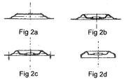
- Figures 2a, 2b, 2c, 2d show a sequence of operations necessary for the production of a wheel according to the invention.
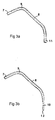
- Figures 3a and 3b are two axial sections of two wheel webs respectively conventional and according to the invention.
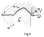
- Figure 4 is a block diagram of the shape of the wheel disc according to the invention, on the stamping tool according to the invention.
- the method according to the invention relates to the production of a wheel 1 of land motor vehicle, as shown in FIG. 1, comprising generally, a wheel disc 2 and a rim 3 substantially cylindrical, the wheel surface 2 being obtained from a sheet metal blank 4 of determined thickness subjected in particular to several setting operations shaped, and consisting of a substantially planar central portion 5 having a bearing surface 6 which is used to center and fix the wheel 1 on the hub of the vehicle axle, a substantially conical inner climb 7, a another inverted conical part 8 defining, with the internal rise 7, a curve nose 9 which has a large radius of curvature, the part inverted conical 8 ending in a fallen edge 10 intended for the connection of the web 2 with the rim 3.
- the sheet metal blank 4 is laminated over the entire periphery of the web 2 so as to preserve the thickness of the sheet if it is optimized or to reduce the thickness of the base sheet depending on the optimization in mechanical characteristics of said wheel 1.
- the problem solved is in particular to size and put the thickness just necessary on the edge. A reduction in thickness on this zone indeed makes it possible to increase the interior diameter of the veil.
- An advantage of the proposed solution is to reduce the thickness of the web of wheel in the area of the fallen edge. This reduction in thickness is achieved during the edge fell operation, included in the drawing range as shown in Figures 2a, 2b, 2c, 2d.
- the operation consists of carry out a rolling of the sheet blank during the operation of the falling edge.
- FIGS. 2a, 2b, 2c The first stamping operations shown diagrammatically in FIGS. 2a, 2b, 2c are conventional.
- Figure 2a shows a first operation stamping for shaping the internal rise 7
- fig 2b presents a second stamping operation for the shaping of the inverted conical part 8
- FIG. 2c shows a cutting operation wheel disc peripheral, before stamping of the fallen edge 10
- the figure 2d shows the wheel disc after completion of the fallen edge 10.
- the cutting diameter can be reduced to take into account of the extra length induced by the rolling operation.
- FIG. 3a gives an image of a section of a vehicle wheel in section axial performed conventionally and Figure 3b gives an image of the same wheel part produced according to the invention.
- the part 11 of the sheet metal blank intended for the realization of the fallen edge is subject to constriction which necessarily entails an increase in the thickness of the sheet blank.
- the implementation form by rolling the part of the sheet metal blank intended for making the edge fallen 10 is subjected to a forced stretch generating an elongation of the part shaping, stretching can either keep the thickness of the sheet metal blank base, or as required, reduce the thickness of the sheet blank so constant or progressive.
- the final edge 12 of the periphery of the laminated part can be beveled instead of being straight.
- the part of the blank intended for the fallen edge can be laminated. with or without festoon, it all depends on the diameter of the chosen cut which follows during the rolling operation of the fallen edge. The presence of a festoon is not crippling. We note that this technique requires press power greater than that used for the conventional operation of falling edge.
- the rolling operation when the edge falls, requires suitable tools.
- the geometry of the tool 15 is adapted to the rolling operation as well as to the reduction in thickness that one wishes to obtain.
- the final thickness of the dropped edge is directly linked to the air gap between the punch 18 and the die 16.
- the dimensioning of the tool 15 must be able to withstand significant efforts, must also withstand friction forces.
- the laminator punch 18 appears as a female cone with an opening angle 21 of 30 °, an entry radius of matrix 22 of 15 mm and an end radius matrix 23, rolling radius, of 20 mm.
- the coating of the tool 15 is important. It conditions the effort value punch, lateral efforts, stripping and also induced or not the wear and seizure phenomenon.
- a coating of TiN, CrN, IC carbon or amorphous carbon is advised.
- the roughness must be significant to allow better trapping of the oil.
- a Ra of the order of 0.3 ⁇ m or 0.4 ⁇ m in the example seems optimum.
- This cutting can also be used to cut the edge in areas that will not be used for the welded connection of the web with the rim.
- the reduction achieved on the wheel according to the invention ultimately reaches approximately 0.3 kg for a 15-inch wheel arch.
- Variant embodiments are located at the position of the cutting, in the process of making the wheel, to lengthen the edge fallen. This cutting can be done before the fall operation of edge or finally with the use of a cam cutout if it is made on the press line or by resumption with the cutting-off tool.
Landscapes
- Engineering & Computer Science (AREA)
- Mechanical Engineering (AREA)
- Braking Arrangements (AREA)
- Shaping Metal By Deep-Drawing, Or The Like (AREA)
- Forging (AREA)
Applications Claiming Priority (2)
| Application Number | Priority Date | Filing Date | Title |
|---|---|---|---|
| FR0008456A FR2810922B1 (fr) | 2000-06-30 | 2000-06-30 | Voile de roue allege et a large espace frein |
| FR0008456 | 2000-06-30 |
Publications (1)
| Publication Number | Publication Date |
|---|---|
| EP1167076A1 true EP1167076A1 (de) | 2002-01-02 |
Family
ID=8851917
Family Applications (1)
| Application Number | Title | Priority Date | Filing Date |
|---|---|---|---|
| EP01401588A Withdrawn EP1167076A1 (de) | 2000-06-30 | 2001-06-18 | Radscheibe, leicht und mit viel Raum für Bremse |
Country Status (4)
| Country | Link |
|---|---|
| US (1) | US20020007556A1 (de) |
| EP (1) | EP1167076A1 (de) |
| JP (1) | JP2002045939A (de) |
| FR (1) | FR2810922B1 (de) |
Cited By (1)
| Publication number | Priority date | Publication date | Assignee | Title |
|---|---|---|---|---|
| US11135641B2 (en) * | 2018-10-09 | 2021-10-05 | Central Motor Wheel Co., Ltd. | Vehicle wheel disc and manufacturing method of vehicle wheel disc |
Families Citing this family (8)
| Publication number | Priority date | Publication date | Assignee | Title |
|---|---|---|---|---|
| US6839967B2 (en) * | 2000-07-21 | 2005-01-11 | Topy Kogyo Kabushiki Kaisha | Lightened disk for a wheel and a method for manufacturing the same |
| BR0201684B1 (pt) * | 2002-05-08 | 2010-08-10 | processo para a fabricação de uma roda, roda e disco de roda. | |
| WO2004112985A1 (ja) * | 2003-06-17 | 2004-12-29 | Honda Motor Co., Ltd. | ホイールリム、ホイール及びその製造方法 |
| JP5281435B2 (ja) * | 2009-02-25 | 2013-09-04 | 中央精機株式会社 | 自動車用ホイール |
| TWI386333B (zh) * | 2010-05-21 | 2013-02-21 | Kwang Yang Motor Co | Locomotive of the double disc evil disc wheel device |
| WO2013137168A1 (ja) * | 2012-03-12 | 2013-09-19 | トピー工業株式会社 | 自動車用ホイールディスクとその製造方法 |
| WO2017085790A1 (ja) | 2015-11-17 | 2017-05-26 | 中央精機株式会社 | ホイールディスクの製造方法、及び、ホイールディスク |
| DE102021125383A1 (de) * | 2021-09-30 | 2023-03-30 | Maxion Wheels Holding Gmbh | Radschüssel für ein Scheibenrad sowie Scheibenrad |
Citations (5)
| Publication number | Priority date | Publication date | Assignee | Title |
|---|---|---|---|---|
| US2406062A (en) * | 1944-08-24 | 1946-08-20 | Standard Forgings Corp | Method for making dished disk wheels |
| US3262191A (en) * | 1962-12-28 | 1966-07-26 | Budd Co | Method of forming wheel disks |
| GB1581927A (en) * | 1976-04-07 | 1980-12-31 | Steel Stampings Ltd | Friction welding of vehicle wheels |
| US5345676A (en) * | 1993-04-28 | 1994-09-13 | Hayes Wheels International, Inc. | Method for producing a full face fabricated vehicle wheel |
| FR2744657A1 (fr) * | 1996-02-08 | 1997-08-14 | Lorraine Laminage | Procede de realisation d'une roue pour vehicule terrestre a moteur |
-
2000
- 2000-06-30 FR FR0008456A patent/FR2810922B1/fr not_active Expired - Fee Related
-
2001
- 2001-06-18 EP EP01401588A patent/EP1167076A1/de not_active Withdrawn
- 2001-06-28 JP JP2001195909A patent/JP2002045939A/ja not_active Withdrawn
- 2001-06-29 US US09/893,500 patent/US20020007556A1/en not_active Abandoned
Patent Citations (5)
| Publication number | Priority date | Publication date | Assignee | Title |
|---|---|---|---|---|
| US2406062A (en) * | 1944-08-24 | 1946-08-20 | Standard Forgings Corp | Method for making dished disk wheels |
| US3262191A (en) * | 1962-12-28 | 1966-07-26 | Budd Co | Method of forming wheel disks |
| GB1581927A (en) * | 1976-04-07 | 1980-12-31 | Steel Stampings Ltd | Friction welding of vehicle wheels |
| US5345676A (en) * | 1993-04-28 | 1994-09-13 | Hayes Wheels International, Inc. | Method for producing a full face fabricated vehicle wheel |
| FR2744657A1 (fr) * | 1996-02-08 | 1997-08-14 | Lorraine Laminage | Procede de realisation d'une roue pour vehicule terrestre a moteur |
Cited By (1)
| Publication number | Priority date | Publication date | Assignee | Title |
|---|---|---|---|---|
| US11135641B2 (en) * | 2018-10-09 | 2021-10-05 | Central Motor Wheel Co., Ltd. | Vehicle wheel disc and manufacturing method of vehicle wheel disc |
Also Published As
| Publication number | Publication date |
|---|---|
| FR2810922A1 (fr) | 2002-01-04 |
| JP2002045939A (ja) | 2002-02-12 |
| US20020007556A1 (en) | 2002-01-24 |
| FR2810922B1 (fr) | 2002-09-13 |
Similar Documents
| Publication | Publication Date | Title |
|---|---|---|
| EP2960531B1 (de) | Werkstück zum festklemmen auf einer halterung, vorrichtung, die ein solches werkstück umfasst, und herstellungsverfahren eines solchen werkstücks und einer solchen vorrichtung | |
| FR2728816A1 (fr) | Procede pour former un element d'arbre et de fourchette monobloc a partir d'un flan de tubage ayant une section transversale generalement circulaire | |
| EP1167076A1 (de) | Radscheibe, leicht und mit viel Raum für Bremse | |
| WO2002058946A1 (fr) | Jante de roue en tole d'acier a profil optimise | |
| EP0778093A1 (de) | Kraftfahrzeugrad | |
| EP4232235B1 (de) | Herstellung ringförmiger sektoren zur herstellung einer lufteinlasslippe | |
| FR2877864A1 (fr) | Fixation de tole par fluo taraude a embase conique | |
| EP1299251B1 (de) | Fahrzeugrad mit montage unter dem felgensitz | |
| FR2470648A1 (fr) | Procede de fabrication par fendage des roues de vehicules et roues obtenues par ce procede | |
| FR2660716A1 (fr) | Piece de moyeu pour un disque d'embrayage et procede de fabrication de celle-ci. | |
| EP2144093A1 (de) | Verfahren zur Formung eines asphärischen optischen Elements | |
| EP0099311A1 (de) | Lenkungszahnstange für Kraftfahrzeuge und Prozess zur Herstellung der Zahnstange | |
| FR2994668A1 (fr) | Roue de vehicule, en particulier de vehicule automobile | |
| EP1335805B1 (de) | Verfahren zur herstellung einer felge eines fahrzeugrades | |
| EP3448694B1 (de) | Kraftfahrzeugrad mit einer felge aus aluminium und einer scheibe aus stahl, die durch geschweisste stifte zusammengefügt sind | |
| FR2667684A1 (fr) | Procede de realisation d'un assemblage tube/fond pour un echangeur de chaleur. | |
| WO2014135772A1 (fr) | Outil pour former une collerette a une extremite d'un tube | |
| EP1473503B1 (de) | Gewellter Schlauch mit zumindest einem metallischen Verstärkungsring und Verfahren zu dessen Herstellung. | |
| FR2836404A1 (fr) | Procede de realisation d'une roue pour vehicule terrestre a moteur comportant une jante allegee | |
| FR2835768A1 (fr) | Procede de fabrication d'une roue monobloc | |
| FR3074093B1 (fr) | Vehicule automobile avec roues hybrides et procede de fabrication | |
| FR3014361A1 (fr) | Roue de vehicule, et procede de fabrication d'une telle roue | |
| FR2727336A1 (fr) | Procede de fluotournage d'une roue de vehicule | |
| FR3070455B1 (fr) | Flanc de couvercle pour mecanisme d'embrayage, couvercle obtenu a partir dudit flanc et procede de fabrication de ce couvercle | |
| EP2138246B1 (de) | Rohr hergestellt aus einem planen Rohling und Verfahren zur Herstellung eines solchen Rohres |
Legal Events
| Date | Code | Title | Description |
|---|---|---|---|
| PUAI | Public reference made under article 153(3) epc to a published international application that has entered the european phase |
Free format text: ORIGINAL CODE: 0009012 |
|
| AK | Designated contracting states |
Kind code of ref document: A1 Designated state(s): AT BE CH CY DE DK ES FI FR GB GR IE IT LI LU MC NL PT SE TR |
|
| AX | Request for extension of the european patent |
Free format text: AL;LT;LV;MK;RO;SI |
|
| 17P | Request for examination filed |
Effective date: 20020702 |
|
| AKX | Designation fees paid |
Free format text: AT BE CH CY DE DK ES FI FR GB GR IE IT LI LU MC NL PT SE TR |
|
| 17Q | First examination report despatched |
Effective date: 20030716 |
|
| GRAP | Despatch of communication of intention to grant a patent |
Free format text: ORIGINAL CODE: EPIDOSNIGR1 |
|
| GRAS | Grant fee paid |
Free format text: ORIGINAL CODE: EPIDOSNIGR3 |
|
| STAA | Information on the status of an ep patent application or granted ep patent |
Free format text: STATUS: THE APPLICATION IS DEEMED TO BE WITHDRAWN |
|
| 18D | Application deemed to be withdrawn |
Effective date: 20040513 |