EP1167092B1 - Querlenker einer Radaufhängung - Google Patents
Querlenker einer Radaufhängung Download PDFInfo
- Publication number
- EP1167092B1 EP1167092B1 EP01110959A EP01110959A EP1167092B1 EP 1167092 B1 EP1167092 B1 EP 1167092B1 EP 01110959 A EP01110959 A EP 01110959A EP 01110959 A EP01110959 A EP 01110959A EP 1167092 B1 EP1167092 B1 EP 1167092B1
- Authority
- EP
- European Patent Office
- Prior art keywords
- wheel
- fixing
- wishbone
- kidney
- zone
- Prior art date
- Legal status (The legal status is an assumption and is not a legal conclusion. Google has not performed a legal analysis and makes no representation as to the accuracy of the status listed.)
- Expired - Lifetime
Links
Images


Classifications
-
- B—PERFORMING OPERATIONS; TRANSPORTING
- B60—VEHICLES IN GENERAL
- B60G—VEHICLE SUSPENSION ARRANGEMENTS
- B60G7/00—Pivoted suspension arms; Accessories thereof
- B60G7/001—Suspension arms, e.g. constructional features
-
- B—PERFORMING OPERATIONS; TRANSPORTING
- B60—VEHICLES IN GENERAL
- B60G—VEHICLE SUSPENSION ARRANGEMENTS
- B60G2206/00—Indexing codes related to the manufacturing of suspensions: constructional features, the materials used, procedures or tools
- B60G2206/01—Constructional features of suspension elements, e.g. arms, dampers, springs
- B60G2206/10—Constructional features of arms
- B60G2206/12—Constructional features of arms with two attachment points on the sprung part of the vehicle
-
- B—PERFORMING OPERATIONS; TRANSPORTING
- B60—VEHICLES IN GENERAL
- B60G—VEHICLE SUSPENSION ARRANGEMENTS
- B60G2206/00—Indexing codes related to the manufacturing of suspensions: constructional features, the materials used, procedures or tools
- B60G2206/01—Constructional features of suspension elements, e.g. arms, dampers, springs
- B60G2206/10—Constructional features of arms
- B60G2206/122—Constructional features of arms the arm having L-shape
-
- B—PERFORMING OPERATIONS; TRANSPORTING
- B60—VEHICLES IN GENERAL
- B60G—VEHICLE SUSPENSION ARRANGEMENTS
- B60G2206/00—Indexing codes related to the manufacturing of suspensions: constructional features, the materials used, procedures or tools
- B60G2206/01—Constructional features of suspension elements, e.g. arms, dampers, springs
- B60G2206/80—Manufacturing procedures
- B60G2206/81—Shaping
- B60G2206/8101—Shaping by casting
Definitions
- the invention relates to a wishbone suspension for a wheel of a motor vehicle comprising a one-piece casting with a mounting portion for attachment to a bearing assembly of the wheel, with further attachment areas for attachment to a chassis of the motor vehicle and a flat area with at least one breakthrough.
- the wishbone establishes on one side the connection with the bearing assembly of the wheel and on the other side the connection with the chassis of the vehicle.
- the bearing assembly comprises, in addition to the wheel bearing and the drive shaft, inter alia, a pivot bearing, a connection with the steering knuckle and a guide joint, with the tie rod and other elements for the steering, the drive, the suspension and the braking of the vehicle.
- the wishbone is subjected to versatile stresses. Often therefore two wishbones per wheel are provided.
- the high stress of the wishbone can be collected with a particularly strong and stable construction. Such a construction often brings a high weight, which leads to increased fuel consumption.
- the safety of the vehicle in the event of a collision requires an optimal design of the control arm.
- From DE 38 00 944 C1 discloses a bearing assembly for a one-piece wishbone suspension is known.
- the wishbone itself is a stiffened component which is connected to the wheel carrier on the side of the wheel.
- the wishbone on two bearing members consisting of bearing journals and bearing bores, which are arranged in alignment with each other in the direction of travel, connected to a longitudinal member of the vehicle body.
- one of the bearing members which is cantilevered, releases.
- the impact energy is not transmitted to the passenger compartment, but absorbed by deformation of the longitudinal member. It also prevents the relatively stiff and heavy control arm from entering the passenger compartment. After a collision, at least the side member must be replaced or repaired.
- the side member of a vehicle is overall much heavier in weight and less accessible than the wishbone.
- Applicant's US 4 556 234 B discloses a cast link for the suspension of motor vehicle wheels.
- the handlebar has a cross section with legs and transverse webs.
- a carrier arm for a vehicle front wheel is known.
- the support arm has attachment portions for attaching the wheel and securing the chassis.
- the support arm has between the attachment areas on a flat area with openings and a thicker edge.
- the impact energy is absorbed by a defined deformation of the control arm. This is achieved in that the area of the transverse link adjacent to the kidney-shaped opening has a ramp with a wall thickness increasing toward the kidney-shaped opening.
- the Wishbone defines deformed without failing due to breakage. This is achieved by arranging a first dumbbell-shaped breakthrough between the ramp and the attachment region for attachment to the bearing assembly of the wheel. This is also achieved in that the second dumbbell-shaped breakthrough between the ends of the dumbbell has a connection region which is tapered towards the first fastening region for attachment to the chassis of the motor vehicle.
- the breakthroughs and the ramp bring with comparable strength a significant weight saving of the wishbone. Through the breakthroughs, the dirty water can run better.
- the breakthroughs can also be used as Dürch entryen for different lines.
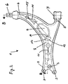
- the control arm 1 shows a transverse link 1 for the suspension of a wheel of a motor vehicle.
- the left front wishbone as seen from the passenger compartment, shown in perspective.
- the control arm 1 is a relatively flat component that can be produced as a one-piece casting 1 made of cast steel, cast iron with nodular graphite or a light metal alloy.
- the wishbone, the one-piece casting 1 for this purpose has a mounting portion 2 with, for example, three holes 3 for attachment to a bearing assembly or on a guide leg of the wheel.
- the holes 3 can be used as bushes made of steel or other alloy prior to casting into the mold to form after casting a firm connection with the mounting portion 2 for attachment of the wheel bearing assembly, not shown here.
- the casting 1 On the side of the chassis, which is also not shown here, the casting 1 has two further attachment portions 4, 5 for attachment to the chassis of the vehicle.
- the axes of the bearing pin 6 and the bearing bush 7 are aligned with each other.
- a movement of the Radbefest Dermats Surreyes 2 is made possible around an axis which extends in the direction of travel.
- further resilient elements such as a rubber pad in the bushing 7 or the pin 6 and by the resilient suspension so an up and down movement of the wheel, for example, allows unevenness of the road.
- the casting 1 has a flat region 8 between the wheel attachment region 2 and the chassis attachment regions 4, 5. In this area 8 apertures 9, 10, 11 recessed. A first kidney shaped aperture 9 is located near the center of gravity of the triangle formed by the three attachment portions 2,4,5. Between the kidney-shaped opening 9 and the wheel mounting area 2 borders on kidney-shaped opening 9 a ramp 12 at. The ramp 12 is placed on the flat area 8 like a laterally beveled prism. The ramp 12 begins with a baseline 13 in the area 8 and ends in a tip 14, which is adjacent to one side of the kidney-shaped aperture 9, which faces the Radbefest Trents Kunststoffs 2.
- the area 8 has a wall thickness which increases toward the kidney-shaped opening 9.
- This ramp 12 with variable wall thickness to high voltages are prevented in the area 8 at a load, for example in the event of a collision.
- the areas of the control arm 1, which are subjected to train and pressure, are clearly separated from each other by the formation of the ramp 12 adjacent to the kidney-shaped opening 9. The stresses that occur in this area in the control arm are distributed more evenly and therefore lower. As a result, a fracture of the casting 1 is prevented and it is achieved a targeted deformation of the casting.
- dumbbell-shaped openings 10, 11 A first dumbbell-shaped opening 10 is formed between the ramp 12 and the wheel mounting area 2.
- the second dumbbell-shaped aperture 11 is formed between the kidney-shaped aperture 9 and the first chassis mounting portion 4 which is connected to the chassis on the side of the passenger compartment.
- the openings 10,11 dumbbell-shaped or in the form of key holes 10, 11 are formed.
- the second dumbbell-shaped aperture 11 has, between the ends of the dumbbell, a connection region 13 which tapers towards the first chassis attachment region 4.
- the Weight of the wishbone Due to the formation of the ramp 12 and through the recess of the kidney-shaped and / or dumbbell-shaped openings 9, 10, 11 is the Weight of the wishbone considerably reduced.
- the wall thickness of the area 8 is reduced to the minimum necessary for the safety and strength requirements.
- the wishbone will only deform and not break. Impact energy is absorbed by warp deformation and not deformation of other hard-to-reach vehicle components that must perform other important tasks in the design of the vehicle, such as carrying the engine block and passenger compartment.
- the wishbone is in comparison to the side member a smaller and easier to replace component of the motor vehicle. The vehicle repair is cheaper and less time consuming.
- FIG. 2 shows a plan view of a transverse link 1.
- the axes of the bearing pin 6 and the bearing bush 7 are arranged in alignment with each other.
- the taper of the connecting portion 15 of the second dumbbell-shaped aperture 11 is clearly visible.
- the formation of the ramp 12, which extends from the base line 13 with increasing wall thickness of the area 8 to the surface area 14, can also be seen in FIG.
- FIG. 3 the inventive control arm 1 is shown in section.
- the section of FIG. 3 runs along a line which is shown in FIG. 2 as a broken and angled dashed line BB.
- BB dashed line
Landscapes
- Engineering & Computer Science (AREA)
- Mechanical Engineering (AREA)
- Vehicle Body Suspensions (AREA)
- Body Structure For Vehicles (AREA)
- Transition And Organic Metals Composition Catalysts For Addition Polymerization (AREA)
Description
- Die Erfindung bezieht sich auf einen Querlenker einer Radaufhängung für ein Rad eines Kraftfahrzeuges umfassend ein einstückiges Gussteil mit einem Befestigungsbereich zur Befestigung an einer Lageranordnung des Rades, mit weiteren Befestigungsbereichen zur Befestigung an einem Chassis des Kraftfahrzeuges und mit einem flächigen Bereich mit mindestens einem Durchbruch.
- Im Kraftfahrzeugbau dienen Querlenker für die Führung und Lenkung der Räder. Der Querlenker stellt auf der einen Seite die Verbindung mit der Lageranordnung des Rades und auf der anderen Seite die Verbindung mit dem Chassis des Fahrzeuges her. Die Lageranordnung umfasst neben dem Radlager und die Antriebswelle unter anderem auch ein Schwenklager, eine Verbindung mit dem Achsschenkel und mit einem Führungsgelenk, mit der Spurstange sowie weitere Elemente für die Lenkung, den Antrieb, die Federung und die Bremsung des Fahrzeuges. Im Betrieb des Fahrzeuges ist der Querlenker vielseitige Beanspruchungen ausgesetzt. Oft sind deshalb auch pro Rad zwei Querlenker vorgesehen. Die hohe Beanspruchung des Querlenkers kann mit einer besonders festen und stabilen Konstruktion aufgefangen werden. Eine solche Konstruktion bringt oft auch ein hohes Gewicht mit sich, was zu erhöhtem Treibstoffverbrauch führt. Auch die Sicherheit des Fahrzeuges im Falle eines Zusammenstosses erfordert eine optimale Auslegung des Querlenkers.
- Aus der DE 38 00 944 C1 ist eine Lageranordnung für einen einteiligen Querlenker einer Radaufhängung bekannt. Der Querlenker selbst ist ein in sich ausgesteiftes Bauteil, das auf der Seite des Rades mit dem Radträger verbunden ist. Auf der anderen Seite ist der Querlenker über zwei Lagerglieder, bestehend aus Lagerzapfen und Lagerbohrungen, die zueinander fluchtend in der Fahrtrichtung angeordnet sind, mit einem Längsträger des Fahrzeugaufbaues verbunden. Im Falle eines Zusammenstosses in oder entgegen der Fahrtrichtung löst sich eines der Lagerglieder, das fliegend gelagert ist. Die Aufprallenergie wird nicht auf die Fahrgastzelle übertragen, sondern durch Verformung des Längsträgers aufgenommen. Es wird auch verhindert, dass der verhältnismässig steife und schwere Querlenker in der Fahrgastzelle eindringt. Nach einem Zusammenstoss muss zumindest der Längsträger ersetzt oder instandgesetzt werden. Der Längsträger eines Fahrzeuges ist insgesamt wesentlich schwerer in Gewicht und schlechter zugänglich als der Querlenker.
- Aus der US 4 556 234 B der Anmelderin ist ein gegossener Lenker für die Aufhängung von Kraftfahrzeugrädern bekannt. Der Lenker weist einen Querschnitt mit Schenkeln und Querstegen auf.
- Aus der JP 61-282 106-A1 ist ein Trägerarm für ein Fahrzeugvorderrad bekannt. Der Trägerarm weist Befestigungsbereiche zur Befestigung des Rades und zur Befestigung des Chassis auf. Der Trägerarm weist zwischen den Befestigungsbereichen ein flächiger Bereich mit Durchbrüchen und einen dickeren Rand auf.
- Ausgehend von diesem Stand der Technik ist es Aufgabe der Erfindung, einen Querlenker einer Radaufhängung anzugeben, mit dem, bei erhöhten Anforderungen der Fahrzeugsicherheit und des Treibstoffverbrauches, das Fahrzeuggewicht und der Aufwand für die Reparatur verringert wird.
- Diese Aufgabe wird gelöst durch einen Querlenker nach Anspruch 1.
- Bevorzugte Weiterbildungen der Erfindung ergeben sich aus den abhängigen Ansprüchen.
- Es ist von Vorteil, dass, im Falle eines Aufpralls des Kraftfahrzeuges, die Aufprallenergie durch eine definierte Verformung des Querlenkers aufgenommen wird. Dies wird dadurch erreicht, dass der flächige Bereich des Querlenkers benachbart zum nierenförmigen Durchbruch eine Rampe mit einer zum nierenförmigen Durchbruch hin zunehmenden Wandstärke aufweist.
- Es ist auch von Vorteil, dass, im Falle eines Aufpralls des Kraftfahrzeuges, der Querlenker sich definiert verformt, ohne durch Bruch zu versagen. Dies wird dadurch erreicht, dass ein erster hantelförmiger Durchbruch zwischen der Rampe und der Befestigungsbereich zur Befestigung an der Lageranordnung des Rades angeordnet ist. Dies wird auch dadurch erreicht, dass der zweite hantelförmige Durchbruch zwischen den Enden der Hantel einen Verbindungsbereich aufweist, der zum ersten Befestigungsbereich zur Befestigung an dem Chassis des Kraftfahrzeuges hin sich verjüngend ausgebildet ist.
- Die Durchbrüche und die Rampe bringen bei vergleichbarer Festigkeit eine erhebliche Gewichtseinsparung des Querlenkers. Durch die Durchbrüche kann das Schmutzwasser besser ablaufen. Die Durchbrüche können auch als Dürchführungen für verschiedene Leitungen verwendet werden.
- Ein Ausführungsbeispiel der Erfindung wird anhand der Figuren beschrieben. Es zeigen:
- Figur 1 eine perspektivische Sicht auf einen erfindungsgemässen Querlenker,
- Figur 2 eine Aufsicht auf den Querlenker von Figur 1 und
- Figur 3 einen Schnitt durch den Querlenker entlang der gebrochnenen Linie BB von Figur 2.
- In Figur 1 ist einen Querlenker 1 für die Aufhängung eines Rades eines Kraftfahrzeuges dargestellt. In Figur 1 ist beispielsweise der linke vordere Querlenker, wie aus der Fahrgastzelle gesehen, perspektivisch dargestellt. Der Querlenker 1 ist ein relativ flaches Bauteil, dass als einstückiges Gussteil 1 aus Stahlguss, aus Gusseisen mit Kugelgraphit oder aus einer Leichtmetalllegierung hergestellt werden kann.
- Auf der linken Seite der Figur 1, d.h. in dem linken vorderen Eckbereich des Fahrzeuges, wird am Querlenker eine hier nicht dargestellte und nicht näher beschriebene Radlageranordnung mit Radträger, Achsschenkel und mit weiteren Elementen für die Lenkung, Federung, Bremsung und Antrieb des Fahrzeuges befestigt. Der Querlenker, das einstückige Gussteil 1, weist hierzu einen Befestigungsbereich 2 mit beispielsweise drei Bohrungen 3 zur Befestigung an eine Lageranordnung oder an einem Führungsschenkel des Rades auf. Die Bohrungen 3 können als Buchsen aus Stahl oder aus einer anderen Legierung vor dem Giessen in die Form eingesetzt werden um nach dem Giessen eine feste Verbindung mit dem Befestigungsbereich 2 zur Befestigung der hier nicht dargestellten Radlageranordnung zu bilden.
- Auf der Seite des Chassis, das hier ebenfalls nicht dargestellt ist, weist das Gussteil 1 zwei weiteren Befestigungsbereiche 4, 5 zur Befestigung an dem Chassis des Fahrzeuges auf. Der erste Chassisbefestigungsbereich 4, der auf der Seite der Fahrgastzelle mit dem Chassis verbunden wird, weist einen Lagerzapfen 6 auf und der zweite Chassisbefestigungsbereich 5, der auf der Frontseite des Fahrzeuges mit dem Chassis verbunden wird, weist eine Lagerbuchse 7 auf. Die Achsen des Lagerzapfens 6 und der Lagerbuchse 7 sind fluchtend zu einander ausgerichtet. Hierdurch wird eine Bewegung des Radbefestigungsbereiches 2 um eine Achse ermöglicht, die in die Fahrtrichtung verläuft. Durch weitere federnde Elemente, wie beispielsweise ein Gummipolster in der Buchse 7 oder um den Zapfen 6 und durch die federnde Radaufhängung wird so eine Auf- und Abbewegung des Rades, beispielsweise bei Unebenheiten der Fahrbahn ermöglicht.
- Das Gussteil 1 weist zwischen dem Radbefestigungsbereich 2 und den Chassisbefestigungsbereichen 4, 5 einen flächigen Bereich 8 auf. In diesem flächigen Bereich 8 sind Durchbrüche 9, 10, 11 ausgespart. Ein erster nierenförmiger Durchbruch 9 befindet sich in der Nähe des Schwerpunktes des Dreieckes, das durch die drei Befestigungsbereiche 2,4,5 gebildet wird. Zwischen dem nierenförmigen Durchbruch 9 und dem Radbefestigungsbereich 2 grenzt am nierenförmigen Durchbruch 9 eine Rampe 12 an. Die Rampe 12 ist wie ein seitlich abgeschrägtes Prisma auf dem flächigen Bereich 8 aufgesetzt. Die Rampe 12 fängt mit einer Basislinie 13 im flächigen Bereich 8 an und endet in einer Spitze 14, die an einer Seite des nierenförmigen Durchbruchs 9 angrenzt, die zum Radbefestigungsbereichs 2 zeigt.
- Im Bereich der Rampe 12 weist der flächige Bereich 8 eine Wandstärke auf, die zum nierenförmigen Durchbruch 9 hin zunimmt. Durch diese Rampe 12 mit variablen Wandstärke werden im flächigen Bereich 8 bei einer Belastung, beispielsweise im Falle eines Zusammenstosses, zu hohe Spannungen verhindert. Die Bereiche des Querlenkers 1, die auf Zug und auf Druck beansprucht werden, werden durch die Ausbildung der Rampe 12 benachbart zum nierenförmigen Durchbruch 9 klar voneinander abgegrenzt. Die Spannungen, die in diesem Bereich im Querlenker auftreten, werden gleichmässiger verteilt und deshalb niedriger. Hierdurch wird einen Bruch des Gussteiles 1 verhindert und es wird eine gezielte Verformung des Gussteiles erreicht.
- Die gleiche Aufgabe erfüllen auch die hantelförmige Durchbrüche 10, 11. Ein erster hantelförmige Durchbruch 10 ist zwischen der Rampe 12 und dem Radbefestigungsbereich 2 ausgebildet. Der zweite hantelförmige Durchbruch 11 ist zwischen dem nierenförmigen Durchbruch 9 und dem ersten Chassisbefestigungsbereich 4, der auf der Seite der Fahrgastzelle mit dem Chassis verbunden wird, ausgebildet. Um die Verformung des Querlenkers in der gewünschten Richtung zu lenken, und um einen Bruch des Querlenkers zu verhindern, sind die Durchbrüche 10,11 hantelförmig oder in der Form von Schlüssellöchern 10, 11 ausgebildet. Der zweite hantelförmige Durchbruch 11 weist zwischen den Enden der Hantel einen Verbindungsbereich 13 auf, der sich zum ersten Chassisbefestigungssbereich 4 hin verjüngt.
- Durch die Ausbildung der Rampe 12 und durch die Aussparung der nierenförmigen und/oder hantelförmigen Durchbrüchen 9, 10, 11 wird das Gewicht des Querlenkers erheblich reduziert. Die Wandstärke des flächigen Bereichs 8 wird reduziert auf das Minimum, das für die Sicherheits- und Festigkeitsanforderungen notwendig ist. Im Falle eines Aufpralls des Fahrzeuges wird sich der Querlenker lediglich verformen und nicht brechen. Die Aufprallenergie wird durch die Verformung des Querlenkers aufgenommen und nicht durch die Verformung von anderen schwer zugänglichen Fahrzeugbauteilen, die andere wichtige Aufgaben für die Konstruktion des Fahrzeuges, wie beispielsweise das Tragen des Motorblockes und der Fahrgastzelle, erfüllen müssen. Der Querlenker ist im Vergleich zum Längsträger ein kleineres und einfacher zu ersetzendes Bauteil des Kraftfahrzeuges. Die Fahrzeugreparatur wird günstiger und weniger zeitraubend.
- In Figur 2 ist eine Aufsicht auf einen Querlenker 1 dargestellt. Hier ist besonders gut ersichtlich, wie die Achsen des Lagerzapfens 6 und der Lagerbuchse 7 zueinander fluchtend angeordnet sind. Auch die Verjüngung des Verbindungsbereiches 15 des zweiten hantelförmigen Durchbruches 11 ist gut ersichtlich. Die Ausbildung der Rampe 12, die von der Basislinie 13 mit zunehmender Wandstärke des Flächigen Bereichs 8 zur Spitze 14 verläuft, ist in Figur 2 ebenfalls ersichtlich.
- In Figur 3 ist der erfindungsgemässe Querlenker 1 geschnitten dargestellt. Der Schnitt von Figur 3 verläuft entlang einer Linie, die in Figur 2 als gebrochene und abgewinkelte Strichlinie BB eingezeichnet ist. Im Schnitt von Figur 3 ist insbesondere die Ausbildung der Rampe 9 entlang der Linie BB gut ersichtlich.
Claims (7)
- Querlenker einer Radaufhängung für ein Rad eines Kraftfahrzeuges umfassend ein einstückiges Gussteil (1) mit einem Befestigungsbereich (2) zur Befestigung an einer Lageranordnung des Rades, mit weiteren Befestigungsbereichen (4,5) zur Befestigung an einem Chassis des Kraftfahrzeuges und mit einem flächigen Bereich (8) mit mindestens einem Durchbruch (9,10,11), wobei der Durchbruch hantelförmig und/oder nierenförmig ausgebildet ist, wobei der flächige Bereich (8) benachbart zum nierenförmigen Durchbruch (9) eine Rampe (12) mit einer zum nierenförmigen Durchbruch (9) hin zunehmenden Wandstärke aufweist, wobei die Rampe (12) an einem dickeren Rand des Durchbruchs (9) anschliesst.
- Querlenker einer Radaufhängung nach dem Anspruch 1, dadurch gekennzeichnet, dass die Rampe (12) benachbart zum nierenförmigen Durchbruch (9) auf der Seite des Befestigungsbereichs (2) zur Befestigung an der Lageranordnung des Rades angeordnet ist.
- Querlenker einer Radaufhängung nach dem der Ansprüche 1 oder 2, dadurch gekennzeichnet, dass ein erster hantelförmiger Durchbruch (10) zwischen der Rampe (12) und dem Befestigungsbereich (2) zur Befestigung an der Lageranordnung des Rades angeordnet ist.
- Querlenker einer Radaufhängung nach einem der Ansprüche 1 bis 3, dadurch gekennzeichnet, dass ein zweiter hantelförmiger Durchbruch (11) zwischen dem der Rampe gegenüberliegenden Seite des nierenförmigen Durchbruchs (9) und einem ersten Befestigungsbereich (4) zur Befestigung an dem Chassis des Kraftfahrzeuges angeordnet ist.
- Querlenker einer Radaufhängung nach einem der Ansprüche 1 bis 4, dadurch gekennzeichnet, dass der zweite hantelförmige Durchbruch (11) zwischen den Enden der Hantel einen Verbindungsbereich (15) aufweist, der zum ersten Befestigungsbereich (4) zur Befestigung an dem Chassis des Kraftfahrzeuges hin sich verjüngend ausgebildet ist.
- Querlenker einer Radaufhängung nach einem der Ansprüche 1 bis 5, dadurch gekennzeichnet, dass der nierenförmige Durchbruch (9) im flächigen Bereich (8) benachbart zum zweiten Befestigungsbereich (5) zur Befestigung an dem Chassis des Kraftfahrzeuges angeordnet ist.
- Querlenker einer Radaufhängung nach einem der Ansprüche 1 bis 6, dadurch gekennzeichnet, dass das Gussteil (1) aus Stahlguss, aus Gusseisen, insbesondere Kugelgraphitgusseisen oder aus Leichtmetallguss, beispielsweise aus Aluminium oder einer Aluminium-Magnesium-Legierung ausgebildet ist.
Applications Claiming Priority (2)
| Application Number | Priority Date | Filing Date | Title |
|---|---|---|---|
| DE10029189A DE10029189A1 (de) | 2000-06-19 | 2000-06-19 | Querlenker einer Radaufhängung |
| DE10029189 | 2000-06-19 |
Publications (3)
| Publication Number | Publication Date |
|---|---|
| EP1167092A2 EP1167092A2 (de) | 2002-01-02 |
| EP1167092A3 EP1167092A3 (de) | 2003-10-22 |
| EP1167092B1 true EP1167092B1 (de) | 2006-03-15 |
Family
ID=7645629
Family Applications (1)
| Application Number | Title | Priority Date | Filing Date |
|---|---|---|---|
| EP01110959A Expired - Lifetime EP1167092B1 (de) | 2000-06-19 | 2001-05-07 | Querlenker einer Radaufhängung |
Country Status (5)
| Country | Link |
|---|---|
| US (1) | US6572126B2 (de) |
| EP (1) | EP1167092B1 (de) |
| AT (1) | ATE320354T1 (de) |
| DE (2) | DE10029189A1 (de) |
| ES (1) | ES2258044T3 (de) |
Cited By (2)
| Publication number | Priority date | Publication date | Assignee | Title |
|---|---|---|---|---|
| DE102008061833A1 (de) | 2008-12-11 | 2010-06-24 | Zf Friedrichshafen Ag | Querlenker eines Kraftfahrzeuges |
| DE102009008839A1 (de) | 2009-02-13 | 2010-08-19 | Volkswagen Ag | Einteiliger Gussquerlenker sowie Verfahren zur Herstellung desselben |
Families Citing this family (35)
| Publication number | Priority date | Publication date | Assignee | Title |
|---|---|---|---|---|
| DE10140288C1 (de) * | 2001-08-16 | 2002-08-29 | Thyssen Krupp Automotive Ag | Querlenker |
| DE10205639A1 (de) * | 2002-02-12 | 2003-08-14 | Volkswagen Ag | Lenker, insbesondere Querlenker für eine Radaufhängung |
| CN100465002C (zh) * | 2002-05-31 | 2009-03-04 | 麦格纳国际公司 | 液压成形的控制臂 |
| FR2841500B1 (fr) * | 2002-06-28 | 2006-01-06 | Auto Chassis Int | Bras monotole de suspension avant de vehicule automobile et procede d'obtention d'un tel bras |
| DE10336470A1 (de) * | 2003-08-08 | 2005-03-03 | Zf Friedrichshafen Ag | Gussbauteil und Verfahren zu dessen Herstellung |
| DE102004056331A1 (de) * | 2004-11-22 | 2006-05-24 | Georg Fischer Fahrzeugtechnik Ag | Sphärogusslegierung und Verfahren zur Herstellung von Gussteilen aus der Sphärogusslegierung |
| US20060108763A1 (en) * | 2004-11-23 | 2006-05-25 | Ray Michael A | Suspension control arm assembly for vehicles |
| DE102005004917B4 (de) * | 2005-02-02 | 2013-02-28 | Benteler Automobiltechnik Gmbh | Lenkerbauteil für Radaufhängungen von Kraftfahrzeugen und Verfahren zu seiner Herstellung |
| ES2361679T3 (es) * | 2005-07-18 | 2011-06-21 | Magna International Inc | Conjunto de brazo de control y rótula. |
| KR100737028B1 (ko) * | 2005-11-01 | 2007-07-09 | 현대자동차주식회사 | 차량용 서스펜션의 로어 암 마운팅 구조 |
| US8033557B2 (en) * | 2006-10-10 | 2011-10-11 | Honda Motor Co., Ltd. | Vehicle suspension system and method |
| DE102006053030A1 (de) * | 2006-11-10 | 2008-05-15 | Dr.Ing.H.C. F. Porsche Ag | Quer- oder Schräglenker |
| DE102007018861A1 (de) | 2007-04-20 | 2008-10-30 | Benteler Automobiltechnik Gmbh | Verwendung einer Stahllegierung |
| DE102007018838A1 (de) | 2007-04-20 | 2008-10-30 | Benteler Automobiltechnik Gmbh | Verwendung einer Stahllegierung |
| KR100921054B1 (ko) * | 2007-10-17 | 2009-10-08 | 현대자동차주식회사 | 이중 판상 부재를 이용한 어퍼 암 |
| US7703783B2 (en) * | 2008-09-17 | 2010-04-27 | Honda Motor Co., Ltd. | Suspension arm having a shaft projecting therefrom and method for press fitting the shaft into a bore of another member |
| DE102009006356B4 (de) * | 2009-01-28 | 2012-04-26 | Zf Friedrichshafen Ag | Querlenker eines Kraftfahrzeuges |
| DE102010020520A1 (de) | 2010-05-14 | 2011-11-17 | Audi Ag | Lenker für eine Radaufhängung eines Kraftfahrzeugs |
| DE102010024634A1 (de) * | 2010-06-22 | 2011-12-22 | Benteler Automobiltechnik Gmbh | Kraftfahrzeuglenker |
| DE102010031891A1 (de) * | 2010-07-21 | 2012-01-26 | Benteler Automobiltechnik Gmbh | Querlenker |
| US20120098228A1 (en) * | 2010-10-20 | 2012-04-26 | Multimatic Inc. | Stamped arm control |
| CN102367041A (zh) * | 2011-05-19 | 2012-03-07 | 浙江瑞朗锻造有限公司 | 一种弯臂 |
| CN102367042B (zh) * | 2011-05-19 | 2013-10-09 | 浙江瑞朗锻造有限公司 | 弯臂锻件 |
| CN102398491A (zh) * | 2011-05-19 | 2012-04-04 | 浙江瑞朗锻造有限公司 | 弯臂 |
| CN102367043B (zh) * | 2011-05-19 | 2014-04-02 | 浙江瑞朗锻造有限公司 | 一种弯臂锻件 |
| WO2013094580A1 (ja) * | 2011-12-21 | 2013-06-27 | 本田技研工業株式会社 | サスペンションアーム取付構造 |
| FR2991611B1 (fr) * | 2012-06-11 | 2014-12-19 | Peugeot Citroen Automobiles Sa | Bras de suspension d'une roue a la caisse d'un vehicule automobile avec renfort continu |
| DE102012025034B4 (de) | 2012-12-19 | 2024-10-24 | Audi Ag | Federlenker für eine Hinterachse |
| KR101427079B1 (ko) * | 2013-06-11 | 2014-08-07 | 주식회사 오스템 | 자동차 현가장치용 로어아암 |
| JP6236291B2 (ja) * | 2013-11-12 | 2017-11-22 | 豊田鉄工株式会社 | サスペンションアームの製造方法 |
| DE102015204643A1 (de) * | 2015-03-13 | 2016-09-15 | Volkswagen Aktiengesellschaft | Gegossener Querlenker für ein Kraftfahrzeug |
| DE102016211675B4 (de) | 2016-06-29 | 2025-07-17 | Ford Global Technologies, Llc | Querlenker für ein Kraftfahrzeug |
| JP7068124B2 (ja) * | 2018-09-28 | 2022-05-16 | 本田技研工業株式会社 | 車両用サスペンションアーム |
| CN114364548B (zh) * | 2019-09-05 | 2024-06-25 | 多媒体股份有限公司 | 无焊缝车辆悬架控制臂 |
| CN113928104B (zh) * | 2021-09-08 | 2024-03-26 | 浙江吉利控股集团有限公司 | 一种用于提升碰撞性能的悬置支架、动力总成结构及汽车 |
Family Cites Families (15)
| Publication number | Priority date | Publication date | Assignee | Title |
|---|---|---|---|---|
| DE615969C (de) * | 1932-12-15 | 1936-08-10 | Daimler Benz Akt Ges | Verbindung der die Raeder tragenden Schwingachsen mit dem Rahmen, insbesondere fuer Kraftfahrzeuge |
| US3110505A (en) * | 1962-02-19 | 1963-11-12 | Donald W Gladden | Reinforcing arrangement for automobile front wheel suspension |
| DE2554715A1 (de) * | 1975-12-05 | 1977-06-08 | Daimler Benz Ag | Radaufhaengung |
| CH659436A5 (de) * | 1982-10-19 | 1987-01-30 | Fischer Ag Georg | Gegossener lenker fuer kraftfahrzeug-radaufhaengungen. |
| JPS61282106A (ja) * | 1985-06-05 | 1986-12-12 | Mazda Motor Corp | 自動車のフロントサスペンシヨン |
| GB2205074B (en) * | 1987-05-23 | 1991-01-23 | Ford Motor Co | Suspension arm assembly |
| DE3800944C1 (en) * | 1988-01-15 | 1989-01-05 | Daimler-Benz Ag, 7000 Stuttgart, De | Bearing arrangement for a one-piece transverse link of a wheel suspension |
| JPH04306111A (ja) * | 1991-03-31 | 1992-10-28 | Mazda Motor Corp | サスペンションアームの取付構造 |
| JP3737837B2 (ja) * | 1994-06-24 | 2006-01-25 | トヨタ自動車株式会社 | 車両用サスペンションアーム |
| SE502904C2 (sv) * | 1994-06-28 | 1996-02-19 | Volvo Ab | Anordning vid en framhjulsupphängning av typ McPherson för motorfordon |
| US5516130A (en) * | 1994-12-22 | 1996-05-14 | Interstate Forging Industries Inc. | Forged control arm |
| JP3191654B2 (ja) * | 1995-08-30 | 2001-07-23 | トヨタ自動車株式会社 | サスペンションアーム |
| US5879026A (en) * | 1995-12-19 | 1999-03-09 | Chrysler Corporation | Vehicle suspension and steering cradle |
| BR9813506A (pt) * | 1997-12-12 | 2000-10-17 | Holland Neway Int Inc | Suspensão dianteira independente dirigìvel |
| JP2001271874A (ja) * | 2000-03-27 | 2001-10-05 | Tokai Rubber Ind Ltd | 車両用制振装置 |
-
2000
- 2000-06-19 DE DE10029189A patent/DE10029189A1/de not_active Withdrawn
-
2001
- 2001-05-07 DE DE50109191T patent/DE50109191D1/de not_active Expired - Lifetime
- 2001-05-07 EP EP01110959A patent/EP1167092B1/de not_active Expired - Lifetime
- 2001-05-07 AT AT01110959T patent/ATE320354T1/de not_active IP Right Cessation
- 2001-05-07 ES ES01110959T patent/ES2258044T3/es not_active Expired - Lifetime
- 2001-06-18 US US09/883,519 patent/US6572126B2/en not_active Expired - Fee Related
Cited By (2)
| Publication number | Priority date | Publication date | Assignee | Title |
|---|---|---|---|---|
| DE102008061833A1 (de) | 2008-12-11 | 2010-06-24 | Zf Friedrichshafen Ag | Querlenker eines Kraftfahrzeuges |
| DE102009008839A1 (de) | 2009-02-13 | 2010-08-19 | Volkswagen Ag | Einteiliger Gussquerlenker sowie Verfahren zur Herstellung desselben |
Also Published As
| Publication number | Publication date |
|---|---|
| EP1167092A3 (de) | 2003-10-22 |
| ES2258044T3 (es) | 2006-08-16 |
| US6572126B2 (en) | 2003-06-03 |
| DE50109191D1 (de) | 2006-05-11 |
| US20020000705A1 (en) | 2002-01-03 |
| ATE320354T1 (de) | 2006-04-15 |
| EP1167092A2 (de) | 2002-01-02 |
| DE10029189A1 (de) | 2001-12-20 |
Similar Documents
| Publication | Publication Date | Title |
|---|---|---|
| EP1167092B1 (de) | Querlenker einer Radaufhängung | |
| DE102010020816B4 (de) | Achsanordnung | |
| DE4213105C2 (de) | Vorderradaufhängung für Kraftfahrzeuge, insbesondere Autobusse | |
| EP1080953A1 (de) | Radaufhängung für Kraftfahrzeuge mit einer radführenden Blattfeder | |
| DE29718557U1 (de) | Achsschenkel | |
| DE102009042060A1 (de) | Strukturbauteil für Hinterrahmenstruktur eines Kraftfahrzeugs | |
| WO2011113514A1 (de) | Radträger für eine mehrlenker - einzelradaufhängung | |
| DE102015224894A1 (de) | Hinterachshilfsrahmen sowie Kraftfahrzeug mit einem derartigen Hinterachshilfsrahmen | |
| EP1904318B1 (de) | Lenker für eine fahrzeugradaufhängung mit einer sollbruchstelle | |
| DE102015204739B4 (de) | Schwenklager | |
| DE19580267B4 (de) | Anordnung zur Aufhängung eines gefederten Fahrzeug-Fahrerhauses an einem Fahrzeugrahmen | |
| DE19937336A1 (de) | Trägeranordnung für Kraftfahrzeuge | |
| EP0899133B1 (de) | Einzelradaufhängung einer Hinterachse | |
| DE19923698A1 (de) | Querlenker | |
| DE3879404T2 (de) | Lagervorrichtung fuer kippbare fahrerkabinen von nutzfahrzeugen. | |
| EP2780182A1 (de) | Starrachse mit luftfederung | |
| EP0788903B1 (de) | Verfahren zur Herstellung einer Verbundlenkerachse für Kraftfahrzeuge und Verbundlenkerachse | |
| DE29519965U1 (de) | Kfz-Radträger für Mehrlenkerachsen | |
| EP2161183A1 (de) | Sattelkupplung | |
| DE3707155C2 (de) | ||
| DE102019100271B4 (de) | Achsträger für ein Kraftfahrzeug | |
| DE3710892C2 (de) | ||
| DE102017126975B3 (de) | Achsträger mit Verstärkungsbügel | |
| DE19849752B4 (de) | Flurförderzeug mit einem neigbaren Hubgerüst | |
| DE60002789T2 (de) | Hinterradaufhängung für ein Kraftfahrzeug |
Legal Events
| Date | Code | Title | Description |
|---|---|---|---|
| PUAI | Public reference made under article 153(3) epc to a published international application that has entered the european phase |
Free format text: ORIGINAL CODE: 0009012 |
|
| AK | Designated contracting states |
Kind code of ref document: A2 Designated state(s): AT BE CH CY DE DK ES FI FR GB GR IE IT LI LU MC NL PT SE TR |
|
| AX | Request for extension of the european patent |
Free format text: AL;LT;LV;MK;RO;SI |
|
| PUAL | Search report despatched |
Free format text: ORIGINAL CODE: 0009013 |
|
| AK | Designated contracting states |
Kind code of ref document: A3 Designated state(s): AT BE CH CY DE DK ES FI FR GB GR IE IT LI LU MC NL PT SE TR |
|
| AX | Request for extension of the european patent |
Extension state: AL LT LV MK RO SI |
|
| 17P | Request for examination filed |
Effective date: 20031029 |
|
| 17Q | First examination report despatched |
Effective date: 20040325 |
|
| AKX | Designation fees paid |
Designated state(s): AT BE CH CY DE DK ES FI FR GB GR IE IT LI LU MC NL PT SE TR |
|
| GRAP | Despatch of communication of intention to grant a patent |
Free format text: ORIGINAL CODE: EPIDOSNIGR1 |
|
| GRAS | Grant fee paid |
Free format text: ORIGINAL CODE: EPIDOSNIGR3 |
|
| GRAA | (expected) grant |
Free format text: ORIGINAL CODE: 0009210 |
|
| AK | Designated contracting states |
Kind code of ref document: B1 Designated state(s): AT BE CH CY DE DK ES FI FR GB GR IE IT LI LU MC NL PT SE TR |
|
| PG25 | Lapsed in a contracting state [announced via postgrant information from national office to epo] |
Ref country code: IE Free format text: LAPSE BECAUSE OF FAILURE TO SUBMIT A TRANSLATION OF THE DESCRIPTION OR TO PAY THE FEE WITHIN THE PRESCRIBED TIME-LIMIT Effective date: 20060315 Ref country code: NL Free format text: LAPSE BECAUSE OF FAILURE TO SUBMIT A TRANSLATION OF THE DESCRIPTION OR TO PAY THE FEE WITHIN THE PRESCRIBED TIME-LIMIT Effective date: 20060315 Ref country code: FI Free format text: LAPSE BECAUSE OF FAILURE TO SUBMIT A TRANSLATION OF THE DESCRIPTION OR TO PAY THE FEE WITHIN THE PRESCRIBED TIME-LIMIT Effective date: 20060315 |
|
| REG | Reference to a national code |
Ref country code: GB Ref legal event code: FG4D Free format text: NOT ENGLISH Ref country code: CH Ref legal event code: EP |
|
| GBT | Gb: translation of ep patent filed (gb section 77(6)(a)/1977) |
Effective date: 20060315 |
|
| REG | Reference to a national code |
Ref country code: IE Ref legal event code: FG4D Free format text: LANGUAGE OF EP DOCUMENT: GERMAN |
|
| PG25 | Lapsed in a contracting state [announced via postgrant information from national office to epo] |
Ref country code: AT Free format text: LAPSE BECAUSE OF NON-PAYMENT OF DUE FEES Effective date: 20060507 |
|
| REF | Corresponds to: |
Ref document number: 50109191 Country of ref document: DE Date of ref document: 20060511 Kind code of ref document: P |
|
| PG25 | Lapsed in a contracting state [announced via postgrant information from national office to epo] |
Ref country code: MC Free format text: LAPSE BECAUSE OF NON-PAYMENT OF DUE FEES Effective date: 20060531 Ref country code: BE Free format text: LAPSE BECAUSE OF NON-PAYMENT OF DUE FEES Effective date: 20060531 Ref country code: CH Free format text: LAPSE BECAUSE OF NON-PAYMENT OF DUE FEES Effective date: 20060531 Ref country code: LI Free format text: LAPSE BECAUSE OF NON-PAYMENT OF DUE FEES Effective date: 20060531 |
|
| PG25 | Lapsed in a contracting state [announced via postgrant information from national office to epo] |
Ref country code: SE Free format text: LAPSE BECAUSE OF FAILURE TO SUBMIT A TRANSLATION OF THE DESCRIPTION OR TO PAY THE FEE WITHIN THE PRESCRIBED TIME-LIMIT Effective date: 20060615 Ref country code: DK Free format text: LAPSE BECAUSE OF FAILURE TO SUBMIT A TRANSLATION OF THE DESCRIPTION OR TO PAY THE FEE WITHIN THE PRESCRIBED TIME-LIMIT Effective date: 20060615 |
|
| PG25 | Lapsed in a contracting state [announced via postgrant information from national office to epo] |
Ref country code: PT Free format text: LAPSE BECAUSE OF FAILURE TO SUBMIT A TRANSLATION OF THE DESCRIPTION OR TO PAY THE FEE WITHIN THE PRESCRIBED TIME-LIMIT Effective date: 20060816 |
|
| REG | Reference to a national code |
Ref country code: ES Ref legal event code: FG2A Ref document number: 2258044 Country of ref document: ES Kind code of ref document: T3 |
|
| ET | Fr: translation filed | ||
| NLV1 | Nl: lapsed or annulled due to failure to fulfill the requirements of art. 29p and 29m of the patents act | ||
| REG | Reference to a national code |
Ref country code: IE Ref legal event code: FD4D |
|
| REG | Reference to a national code |
Ref country code: CH Ref legal event code: PL |
|
| PLBE | No opposition filed within time limit |
Free format text: ORIGINAL CODE: 0009261 |
|
| STAA | Information on the status of an ep patent application or granted ep patent |
Free format text: STATUS: NO OPPOSITION FILED WITHIN TIME LIMIT |
|
| 26N | No opposition filed |
Effective date: 20061218 |
|
| BERE | Be: lapsed |
Owner name: GEORG FISCHER FAHRZEUGTECHNIK A.G. Effective date: 20060531 |
|
| PG25 | Lapsed in a contracting state [announced via postgrant information from national office to epo] |
Ref country code: GR Free format text: LAPSE BECAUSE OF FAILURE TO SUBMIT A TRANSLATION OF THE DESCRIPTION OR TO PAY THE FEE WITHIN THE PRESCRIBED TIME-LIMIT Effective date: 20060616 |
|
| PG25 | Lapsed in a contracting state [announced via postgrant information from national office to epo] |
Ref country code: LU Free format text: LAPSE BECAUSE OF NON-PAYMENT OF DUE FEES Effective date: 20060507 Ref country code: TR Free format text: LAPSE BECAUSE OF FAILURE TO SUBMIT A TRANSLATION OF THE DESCRIPTION OR TO PAY THE FEE WITHIN THE PRESCRIBED TIME-LIMIT Effective date: 20060315 |
|
| PG25 | Lapsed in a contracting state [announced via postgrant information from national office to epo] |
Ref country code: CY Free format text: LAPSE BECAUSE OF FAILURE TO SUBMIT A TRANSLATION OF THE DESCRIPTION OR TO PAY THE FEE WITHIN THE PRESCRIBED TIME-LIMIT Effective date: 20060315 |
|
| REG | Reference to a national code |
Ref country code: FR Ref legal event code: PLFP Year of fee payment: 16 |
|
| REG | Reference to a national code |
Ref country code: FR Ref legal event code: PLFP Year of fee payment: 17 |
|
| PGFP | Annual fee paid to national office [announced via postgrant information from national office to epo] |
Ref country code: GB Payment date: 20170519 Year of fee payment: 17 Ref country code: FR Payment date: 20170523 Year of fee payment: 17 Ref country code: DE Payment date: 20170523 Year of fee payment: 17 |
|
| PGFP | Annual fee paid to national office [announced via postgrant information from national office to epo] |
Ref country code: IT Payment date: 20170526 Year of fee payment: 17 Ref country code: ES Payment date: 20170627 Year of fee payment: 17 |
|
| REG | Reference to a national code |
Ref country code: DE Ref legal event code: R119 Ref document number: 50109191 Country of ref document: DE |
|
| GBPC | Gb: european patent ceased through non-payment of renewal fee |
Effective date: 20180507 |
|
| PG25 | Lapsed in a contracting state [announced via postgrant information from national office to epo] |
Ref country code: GB Free format text: LAPSE BECAUSE OF NON-PAYMENT OF DUE FEES Effective date: 20180507 Ref country code: DE Free format text: LAPSE BECAUSE OF NON-PAYMENT OF DUE FEES Effective date: 20181201 Ref country code: IT Free format text: LAPSE BECAUSE OF NON-PAYMENT OF DUE FEES Effective date: 20180507 Ref country code: FR Free format text: LAPSE BECAUSE OF NON-PAYMENT OF DUE FEES Effective date: 20180531 |
|
| REG | Reference to a national code |
Ref country code: ES Ref legal event code: FD2A Effective date: 20190913 |
|
| PG25 | Lapsed in a contracting state [announced via postgrant information from national office to epo] |
Ref country code: ES Free format text: LAPSE BECAUSE OF NON-PAYMENT OF DUE FEES Effective date: 20180508 |