EP1167112B1 - Energieversorgungssystem für elektrisch betriebene Fahrzeuge - Google Patents
Energieversorgungssystem für elektrisch betriebene Fahrzeuge Download PDFInfo
- Publication number
- EP1167112B1 EP1167112B1 EP01401569A EP01401569A EP1167112B1 EP 1167112 B1 EP1167112 B1 EP 1167112B1 EP 01401569 A EP01401569 A EP 01401569A EP 01401569 A EP01401569 A EP 01401569A EP 1167112 B1 EP1167112 B1 EP 1167112B1
- Authority
- EP
- European Patent Office
- Prior art keywords
- vehicle
- charge
- terminal
- power
- computer
- Prior art date
- Legal status (The legal status is an assumption and is not a legal conclusion. Google has not performed a legal analysis and makes no representation as to the accuracy of the status listed.)
- Expired - Lifetime
Links
- 238000004891 communication Methods 0.000 claims description 6
- 238000000034 method Methods 0.000 claims description 5
- 230000006870 function Effects 0.000 claims description 4
- 238000004146 energy storage Methods 0.000 description 17
- 238000007599 discharging Methods 0.000 description 3
- 229920001971 elastomer Polymers 0.000 description 3
- 239000005060 rubber Substances 0.000 description 3
- 241000135309 Processus Species 0.000 description 2
- 238000010586 diagram Methods 0.000 description 2
- 230000005611 electricity Effects 0.000 description 2
- 210000000056 organ Anatomy 0.000 description 2
- 238000012550 audit Methods 0.000 description 1
- 229910001416 lithium ion Inorganic materials 0.000 description 1
- 230000036515 potency Effects 0.000 description 1
- 230000001105 regulatory effect Effects 0.000 description 1
Images

Classifications
-
- B—PERFORMING OPERATIONS; TRANSPORTING
- B60—VEHICLES IN GENERAL
- B60M—POWER SUPPLY LINES, AND DEVICES ALONG RAILS, FOR ELECTRICALLY- PROPELLED VEHICLES
- B60M7/00—Power lines or rails specially adapted for electrically-propelled vehicles of special types, e.g. suspension tramway, ropeway, underground railway
- B60M7/003—Power lines or rails specially adapted for electrically-propelled vehicles of special types, e.g. suspension tramway, ropeway, underground railway for vehicles using stored power (e.g. charging stations)
-
- B—PERFORMING OPERATIONS; TRANSPORTING
- B60—VEHICLES IN GENERAL
- B60L—PROPULSION OF ELECTRICALLY-PROPELLED VEHICLES; SUPPLYING ELECTRIC POWER FOR AUXILIARY EQUIPMENT OF ELECTRICALLY-PROPELLED VEHICLES; ELECTRODYNAMIC BRAKE SYSTEMS FOR VEHICLES IN GENERAL; MAGNETIC SUSPENSION OR LEVITATION FOR VEHICLES; MONITORING OPERATING VARIABLES OF ELECTRICALLY-PROPELLED VEHICLES; ELECTRIC SAFETY DEVICES FOR ELECTRICALLY-PROPELLED VEHICLES
- B60L50/00—Electric propulsion with power supplied within the vehicle
- B60L50/40—Electric propulsion with power supplied within the vehicle using propulsion power supplied by capacitors
-
- B—PERFORMING OPERATIONS; TRANSPORTING
- B60—VEHICLES IN GENERAL
- B60L—PROPULSION OF ELECTRICALLY-PROPELLED VEHICLES; SUPPLYING ELECTRIC POWER FOR AUXILIARY EQUIPMENT OF ELECTRICALLY-PROPELLED VEHICLES; ELECTRODYNAMIC BRAKE SYSTEMS FOR VEHICLES IN GENERAL; MAGNETIC SUSPENSION OR LEVITATION FOR VEHICLES; MONITORING OPERATING VARIABLES OF ELECTRICALLY-PROPELLED VEHICLES; ELECTRIC SAFETY DEVICES FOR ELECTRICALLY-PROPELLED VEHICLES
- B60L53/00—Methods of charging batteries, specially adapted for electric vehicles; Charging stations or on-board charging equipment therefor; Exchange of energy storage elements in electric vehicles
- B60L53/30—Constructional details of charging stations
- B60L53/32—Constructional details of charging stations by charging in short intervals along the itinerary, e.g. during short stops
-
- Y—GENERAL TAGGING OF NEW TECHNOLOGICAL DEVELOPMENTS; GENERAL TAGGING OF CROSS-SECTIONAL TECHNOLOGIES SPANNING OVER SEVERAL SECTIONS OF THE IPC; TECHNICAL SUBJECTS COVERED BY FORMER USPC CROSS-REFERENCE ART COLLECTIONS [XRACs] AND DIGESTS
- Y02—TECHNOLOGIES OR APPLICATIONS FOR MITIGATION OR ADAPTATION AGAINST CLIMATE CHANGE
- Y02T—CLIMATE CHANGE MITIGATION TECHNOLOGIES RELATED TO TRANSPORTATION
- Y02T10/00—Road transport of goods or passengers
- Y02T10/60—Other road transportation technologies with climate change mitigation effect
- Y02T10/70—Energy storage systems for electromobility, e.g. batteries
-
- Y—GENERAL TAGGING OF NEW TECHNOLOGICAL DEVELOPMENTS; GENERAL TAGGING OF CROSS-SECTIONAL TECHNOLOGIES SPANNING OVER SEVERAL SECTIONS OF THE IPC; TECHNICAL SUBJECTS COVERED BY FORMER USPC CROSS-REFERENCE ART COLLECTIONS [XRACs] AND DIGESTS
- Y02—TECHNOLOGIES OR APPLICATIONS FOR MITIGATION OR ADAPTATION AGAINST CLIMATE CHANGE
- Y02T—CLIMATE CHANGE MITIGATION TECHNOLOGIES RELATED TO TRANSPORTATION
- Y02T10/00—Road transport of goods or passengers
- Y02T10/60—Other road transportation technologies with climate change mitigation effect
- Y02T10/7072—Electromobility specific charging systems or methods for batteries, ultracapacitors, supercapacitors or double-layer capacitors
-
- Y—GENERAL TAGGING OF NEW TECHNOLOGICAL DEVELOPMENTS; GENERAL TAGGING OF CROSS-SECTIONAL TECHNOLOGIES SPANNING OVER SEVERAL SECTIONS OF THE IPC; TECHNICAL SUBJECTS COVERED BY FORMER USPC CROSS-REFERENCE ART COLLECTIONS [XRACs] AND DIGESTS
- Y02—TECHNOLOGIES OR APPLICATIONS FOR MITIGATION OR ADAPTATION AGAINST CLIMATE CHANGE
- Y02T—CLIMATE CHANGE MITIGATION TECHNOLOGIES RELATED TO TRANSPORTATION
- Y02T90/00—Enabling technologies or technologies with a potential or indirect contribution to GHG emissions mitigation
- Y02T90/10—Technologies relating to charging of electric vehicles
- Y02T90/12—Electric charging stations
Definitions
- the present invention relates to a power supply system for electric vehicles.
- the invention relates to a power system for managing the power supply of electric traction vehicles and energy storage, intended to perform a regular route staggered stops, as is the case for urban transport vehicles in public service.
- FR 2 757 806 there is furthermore known a device for supplying an electric traction vehicle by means of which the traction energy is supplied by the series combination of a storage battery and a battery of supercapacitors, the voltage of supply of the traction motor or motors being taken either at the terminals of the accumulator battery or at the terminals of the two batteries in series.
- a switching device determines the two operating speeds according to the direction of the supply current and the value of the voltage across the supercapacitor battery.
- the main concern is to effectively manage the consumption of stored energy, in particular by recovering the braking energy of the vehicle using supercapacitors.
- the document does not address the problems of supplying electrical energy to both batteries from an external source.
- the aim of the invention is to provide an electric power supply system for an electric traction vehicle by which the load of the vehicle energy storage device can be realized quickly and automatically, the charge level of a charging device.
- on-board energy storage that can be closely monitored and regulated according to the energy requirements of that vehicle.
- the subject of the invention is therefore an electrical energy supply system comprising, in combination, in at least one electric traction vehicle, an energy storage device, and at least one fixed charging terminal with respect to the ground, and connection means provided respectively on said vehicle and said terminal for, when the vehicle is placed in the vicinity of the terminal, transferring electrical energy from this terminal to said energy storage device, said terminal comprising a battery of supercapacitors which can be connected to said connection means for supplying the electrical energy to be transferred to said vehicle during the presence thereof near said terminal, means being provided therein for charging said supercapacitor battery when the vehicle is remote therefrom.
- connection means provided respectively on said vehicle and said terminal for, when the vehicle is placed in the vicinity of the terminal, transferring electrical energy from this terminal to said energy storage device
- said terminal comprising a battery of supercapacitors which can be connected to said connection means for supplying the electrical energy to be transferred to said vehicle during the presence thereof near said terminal, means being provided therein for charging said supercapacitor battery when the vehicle is remote therefrom.
- the electrical energy supply system is characterized in that it comprises a computer provided on board the vehicle and whose memory contains data relating to the path to be made by the vehicle, this computer being arranged for, from data of location applied to it, and data on the state of charge of said energy storage device, make a first calculation of the energy requirements of the vehicle to continue its journey after reaching said terminal to receive a new load, said calculator being also arranged to define from said first calculation the amount of energy to be injected into said energy storage device during this new charging operation.
- the recharging of the energy storage device on board the vehicle can be carried out rapidly, since the supercapacitors provided in the charging terminal allow a charge current to be transferred to the vehicle greater than that which can be drawn. of the public electricity distribution network. Furthermore, the charging of the supercapacitors of the charging terminal can be performed relatively slowly with a lower current, while the vehicle is away from the terminal and participates in the circulation.
- the application of the invention to the supply of electrical energy to public transport vehicles intended to serve a regular public service line, for example in an urban environment will be described by way of example.
- the invention is not limited to this application.
- it can be implemented profitably when it comes to supplying any fleet of electric vehicles for commercial use, or even the power supply of a single vehicle with electric traction, in which case the system can have only one charging terminal.
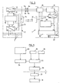
- FIG. 1 there is shown a section of a public transport line consisting of a two-way traffic pavement V1 and V2, one for each direction of travel.
- the public transit line is marked with R refuges to allow, in complete safety for the passengers, the stops of the vehicles of transport with electric traction.
- one of the refuges R is occupied by a vehicle 1 at a standstill to allow the ascent and descent of the passengers.
- Refuges R are equipped with load gantries 2 having a bracket 3 under which a vehicle can be placed and a trunk 4, preferably underground, in which is housed the electrical equipment of the gantry load 2.
- the refuges R are distant from about 300 m, which is obviously not limiting.
- the figure 2 shows that the horizontal branch of the bracket 3 is oriented transversely to the direction of progression of the vehicle 1. It comprises two electrically insulated pads 5a, 5b forming electrodes and mounted spaced apart from each other. These rubbers may have the form of rollers for example, mounted on springs and freely rotating. They are intended to cooperate with pads 6a and 6b mounted with the same spacing on the roof of each vehicle 1 equipping the public transport line.
- the vehicle is preparing to come to a stop position in a refuge R and b) it is stopped. In the latter position, the passengers of the vehicle can go up and down while simultaneously, the rubbers 5a and 5b and the pads 6a and 6b come to contact one another to allow the load of the vehicle 1.
- connection between a vehicle 1 and a gantry 2 can be made by any other known means, for example by a pole or a pantograph coming into contact with the overhead lines stretched in the direction of the vehicle's progression over the area of refuge R.
- FIG 3 there is shown an embodiment of the equipment respectively installed in the trunk 4 of each gantry load 2 and in each electric traction vehicle 1 of the fleet serving the public transport line.
- the trunk 4 is supplied with electrical energy from the public network, for example by three phases 7 of the three-phase network at 380 volts.
- the network supplies a rectifier 8 which supplies electrical energy at a DC voltage via a charge control unit 9 to a supercapacitor battery 10.
- This converter 11 is designed to adapt the voltage of the supercapacitor battery 10 to the vehicle operating voltage 1 .
- the bipolar output of the converter 11 is connected to the wipers 5a and 5b of the bracket 3.
- the rectifier 8 can directly feed the DC / DC converter 11 via the two-wire link 13, provided optionally, this direct connection being able to be established or broken by the control unit 12. In this case, when a transfer of energy between the bracket 3 and the vehicle 1, the charging current can come in parallel with the supercapacitor battery 10 and directly from the rectifier 8.
- the gantry 2 also comprises a transmitter / receiver 14 for communicating with the vehicle 1 via a wireless link, for example over the air.
- the electric traction vehicle 1 comprises a battery of supercapacitors 15 which, via a charge control unit 16, is connected to the pads 6a and 6b of the vehicle.
- the supercapacitor battery 15 is connected to a DC / DC converter 17 responsible for adapting the voltage of this battery to that of a storage battery 18 of LI-Ions type, for example, which is connected to the output of the converter 17
- the storage battery 18 is connected to the on-board network 19 of the vehicle 1 which supplies the traction motor or motors and all the electrical auxiliaries thereof.
- the state of the onboard network is measured by the charge control unit 16 and the corresponding data is transferred to a transmitter / receiver 20 which communicates with the transmitter / receiver 14 of the bracket 3, when the vehicle 1 is located in the range of these transceivers.
- the one or more energy storage batteries 15 and 18 of the vehicle can or can be recharged at regular intervals along a route of the public transport line.
- the supercapacitors 12 are recharged by the distribution network 7 via the rectifier 8, the current and the charging voltage being controlled and monitored by the charge control unit. 9.
- the state of charge data are also communicated to the transmitter / receiver 14.
- the recharging supercapacitors 10 can be made by a charging current carefully adjusted not to impose too much stress on the network 7 and also depending on the frequency of passage of vehicles under the gantry 2 considered.
- the vehicle 1 is equipped with an onboard computer 22 which is intended in particular to determine a number of parameters defining its energy requirements.
- the figure 5 represents symbolically above the dashed line, the calculations that are necessary for this purpose, the part below the dashed line symbolizing certain essential control operations necessary to achieve the recharge of energy storage batteries 15 and 18 of the vehicle.
- the memory of the computer 22 contains the characteristics of the path of the vehicle 1 and the computer receives a position signal using a GPS tracking device (not shown) whose vehicle is equipped.
- the corresponding data may optionally be obtained and / or completed by a learning procedure performed during several test trips made by the vehicle on the prescribed route. They allow the computer 22, at each moment during a run made in operation, to determine (at 23, figure 5 ), the distance separating the vehicle 1 from a refuge R and also other driving data such as the relief of the journey or the commercial speed to be practiced.
- the computer 22 sets the energy requirements of the vehicle (at 24) for the remaining path to be covered to the next refuge R.
- the calculator 22 also permanently (in 25) data relating to the state of charge of the energy storage batteries 15 and 18, as well as data (in 26) defining the parameters concerning the optimal state of charge of these batteries.
- the calculator can determine in 27 the amount of energy that must be supplied to the vehicle 1 at the next stop at a shelter R.
- the corresponding load request signal is sent at 28 by the computer 22 to the transmitter / receiver 20 which communicates to the transmitter / receiver 14 of the bracket 3 of this refuge R as soon as the two transmitters / receivers 14 and 20 are in their mutual range area.
- the vehicle 1 When approaching the refuge R, the vehicle 1 is preferably guided by any appropriate means such as a video camera and ground markings so that it can automatically fit into the refuge R and stop at the moment when the rubbers 5a and 5b and the pads 6a and 6b make contact.
- a position sensor (not shown) may be provided to detect a vertical movement of the wipers 5a and 5b to signal the computer 22 that the vehicle has arrived at the proper position to be loaded.
- switching means (not shown) connected to the converter 11 can be connected only when the correct position signal is delivered to the computer 22.
- the charge demand signal is communicated to the control units 9 and 12 of the bracket 3 so that they determine at 29 the parameters of the energy to be sent to the vehicle 1 and in particular the value of the charging current and the duration of the charging. load. As soon as the amount of energy set by the calculation is sent to the vehicle 1, an end of charge signal is sent to the latter (at 30) to indicate that it can leave the refuge R. This charging process does not require more time than that required for passengers to climb into the vehicle and get off.
- the graphs of the figure 4 represent respectively in a), b) and c) and as a function of time, an example of several charging / discharging cycles of the supercapacitor battery 10, the supercapacitor battery 15 and the storage battery 18, the value of 100% on the ordinate representing the full load of each of these energy storage devices.
- the charge cycles extend in time between stops at refuges R1, R2 and R3. It can be seen that the feed system of the invention makes it possible, during the entire course of the line, to keep the accumulator batteries 18 of the vehicle 1 at a charge level of between 60% and 70%, which for a Li battery -Ions corresponding to an optimal state.
Landscapes
- Engineering & Computer Science (AREA)
- Mechanical Engineering (AREA)
- Power Engineering (AREA)
- Transportation (AREA)
- Electric Propulsion And Braking For Vehicles (AREA)
- Charge And Discharge Circuits For Batteries Or The Like (AREA)
- Forklifts And Lifting Vehicles (AREA)
- Stand-By Power Supply Arrangements (AREA)
- Control Of Washing Machine And Dryer (AREA)
- Vehicle Body Suspensions (AREA)
- Electrical Discharge Machining, Electrochemical Machining, And Combined Machining (AREA)
Claims (5)
- System zur Versorgung mit elektrischer Energie, umfassend, in Kombination, in mindestens einem elektrisch betriebenen Fahrzeug (1) eine Energiespeichervorrichtung (15, 18) und mindestens einen bezüglich des Bodens feststehenden Ladeanschluss (2), wobei an dem Fahrzeug (1) bzw. an dem Ladeanschluss (2) Verbindungsmittel (5a, 5b, 6a, 6b) vorgesehen sind, um, wenn das Fahrzeug sich in Nähe des Anschlusses befindet, von diesem Anschluss zu der Energiespeichervorrichtung (15, 18) elektrische Energie zu übertragen, wobei der Anschluss (2) eine Superkondensatorbatterie (10) umfasst, die mit den Verbindungsmitteln (5a, 5b, 6a, 6b) verbunden werden kann, um elektrische Energie zu liefern, die während der Anwesenheit des Fahrzeugs (1) bei dem Anschluss zu diesem Fahrzeug zu übertragen ist, wobei in dem Anschluss Mittel (7, 8, 9) vorgesehen sind, um die Superkondensatorbatterie (10) zu laden, wenn das Fahrzeug von ihm entfernt ist, dadurch gekennzeichnet, dass es einen Rechner (22) umfasst, der an Bord des Fahrzeugs (1) vorgesehen ist und dessen Speicher Daten enthält, die die von dem Fahrzeug zurückzulegende Fahrstrecke betreffen, wobei dieser Rechner (22) ausgebildet ist, um aus an ihn angelegten Ortungsdaten und aus den Ladezustand der Energiespeichervorrichtung (15, 18) betreffenden Daten eine erste Berechnung des Energiebedarfs des Fahrzeugs durchzuführen, um seine Fahrt fortzusetzen, nachdem es den Anschluss (2) erreicht hat, um eine neue Ladung zu erhalten, wobei der Rechner (22) ferner dafür ausgebildet ist, aus dieser ersten Berechnung die Energiemenge zu bestimmen, die während dieses neuen Ladevorgangs in die Energiespeichervorrichtung (15, 18) einzuspeisen ist.
- Versorgungssystem nach Anspruch 1, dadurch gekennzeichnet, dass der Rechner (22) ferner ausgebildet ist, um diese einzuspeisende Energiemenge in Abhängigkeit von einem optimalen Ladungspegel der Energiespeichervorrichtung (15, 18) zu bestimmen.
- Versorgungssystem nach einem de Ansprüche 1 und 2, dadurch gekennzeichnet, dass es Mittel (14, 20) zur drahtlosen Kommunikation zwischen dem Fahrzeug (1) und dem Ladeanschluss (2) umfasst, um zwischen ihnen den Vorgang der Ladung der Energiespeichervorrichtung (15, 18) betreffende Daten zu übertragen.
- Versorgungssystem nach Anspruch 3, dadurch gekennzeichnet, dass der Rechner (22) ferner ausgebildet ist, um mit Hilfe der drahtlosen Kommunikationsmittel (14, 20) zu dem Ladeanschluss (2) ein Signal zu übertragen, das für die einzuspeisende Energiemenge repräsentativ ist, und dass der Ladeanschluss (2) Mittel (12) umfasst, um ausgehend von diesem repräsentativen Signal die einzuspeisende Energiemenge zu liefern und zum Rechner (22) ein Ladungsendsignal zurückzusenden, wenn die einzuspeisende Energiemenge übertragen wurde.
- Versorgungssystem nach einem der Ansprüche 1 bis 4, dadurch gekennzeichnet, dass es eine Mehrzahl von diesem Ladeanschluss entsprechenden Ladeanschlüssen (2) umfasst, die einen Weg für eine Mehrzahl von Fahrzeugen (1) abstecken, die wie das elektrisch betriebene Fahrzeug ausgerüstet sind, wobei diese Mehrzahl von Fahrzeugen eine öffentliche Verkehrslinie bedienen.
Applications Claiming Priority (2)
| Application Number | Priority Date | Filing Date | Title |
|---|---|---|---|
| FR0007805A FR2810278B1 (fr) | 2000-06-19 | 2000-06-19 | Systeme d'alimentation en energie de vehicules a traction electrique |
| FR0007805 | 2000-06-19 |
Publications (2)
| Publication Number | Publication Date |
|---|---|
| EP1167112A1 EP1167112A1 (de) | 2002-01-02 |
| EP1167112B1 true EP1167112B1 (de) | 2010-07-21 |
Family
ID=8851409
Family Applications (1)
| Application Number | Title | Priority Date | Filing Date |
|---|---|---|---|
| EP01401569A Expired - Lifetime EP1167112B1 (de) | 2000-06-19 | 2001-06-15 | Energieversorgungssystem für elektrisch betriebene Fahrzeuge |
Country Status (4)
| Country | Link |
|---|---|
| EP (1) | EP1167112B1 (de) |
| AT (1) | ATE474735T1 (de) |
| DE (1) | DE60142601D1 (de) |
| FR (1) | FR2810278B1 (de) |
Families Citing this family (6)
| Publication number | Priority date | Publication date | Assignee | Title |
|---|---|---|---|---|
| FR2940201B1 (fr) * | 2008-12-22 | 2014-04-11 | Delachaux Sa | Systemes et ensemble de connexion pour la charge d'un vehicule electrique |
| IT1396053B1 (it) * | 2009-10-01 | 2012-11-09 | Balfour Beatty Rail Spa | Apparecchiatura di alimentazione e telecontrollo asupercondensatore per apparecchiatureelettromeccaniche di linee metrotramviarie efiloviarie |
| CN103738196A (zh) * | 2013-12-03 | 2014-04-23 | 方清 | 一种纯电动商用车集中驱动式电动化辅助动力总成 |
| JP2017530681A (ja) * | 2014-09-25 | 2017-10-12 | アルパイン メディア | 移動体にあるシステムにエネルギーを提供するための方法及びデバイス |
| EP3871941A1 (de) * | 2020-02-29 | 2021-09-01 | Bialka Ski Resort Spolka Z Organiczona Odpowiedzialnoscia | Satz aus station und gondel |
| CN114940083A (zh) * | 2022-05-05 | 2022-08-26 | 许继电源有限公司 | 一种自动充电连接装置 |
Family Cites Families (5)
| Publication number | Priority date | Publication date | Assignee | Title |
|---|---|---|---|---|
| CH287075A (de) * | 1951-02-26 | 1952-11-15 | Oerlikon Maschf | Anordnung zur Sicherheitserdung von Fahrzeugen mit Schwungmassenantrieb. |
| DE2161266A1 (de) * | 1971-12-10 | 1973-06-20 | Vetter Fa Walter | Aufladestation fuer gyrofahrzeuge od.dgl. sowie zugehoeriges stationensystem |
| FR2336272A1 (fr) * | 1975-12-23 | 1977-07-22 | Cotravel | Dispositif de transport de surface par vehicules a moteur electrique de traction alimente par une batterie d'accumulateurs |
| EP0564149B1 (de) * | 1992-04-03 | 1997-09-24 | JEOL Ltd. | Stromversorgung mit Speicherkondensator |
| FR2780684B1 (fr) * | 1998-07-02 | 2002-02-01 | Anf Ind | Reseau de transport en commun avec vehicules electriques |
-
2000
- 2000-06-19 FR FR0007805A patent/FR2810278B1/fr not_active Expired - Lifetime
-
2001
- 2001-06-15 DE DE60142601T patent/DE60142601D1/de not_active Expired - Lifetime
- 2001-06-15 EP EP01401569A patent/EP1167112B1/de not_active Expired - Lifetime
- 2001-06-15 AT AT01401569T patent/ATE474735T1/de not_active IP Right Cessation
Also Published As
| Publication number | Publication date |
|---|---|
| FR2810278B1 (fr) | 2002-10-11 |
| DE60142601D1 (de) | 2010-09-02 |
| EP1167112A1 (de) | 2002-01-02 |
| ATE474735T1 (de) | 2010-08-15 |
| FR2810278A1 (fr) | 2001-12-21 |
Similar Documents
| Publication | Publication Date | Title |
|---|---|---|
| EP0982176B1 (de) | Stromversorgungssystem für ein elektrisch angetriebenes Fahrzeug | |
| EP1938438B1 (de) | Aufladestation und diesbezügliches elektrisches fahrzeug | |
| EP1245432B1 (de) | Verfahren und Vorrichtung zur Steuerung der elektrischen Energieversorgung eines elektrisch angetriebenen Fahrzeuges, bestimmt zum Betrieb in externem oder autonomen Mode | |
| CA2988845C (fr) | Ensemble constitue d'un vehicule electrique et d'un systeme de recharge stationnaire par conduction; systeme, installation, vehicule et procede associes | |
| EP2803523B1 (de) | Dynamisches und vorausschauendes Verwaltungsverfahren der elektrischen Aufladung von Batterien | |
| FR3008041A1 (fr) | Vehicule electrique et installation de transport associee | |
| EP2162313B1 (de) | Einspeisungseinrichtung eines eisenbahnfahrzeugs | |
| WO1995022191A1 (fr) | Systeme d'alimentation de robots mobiles autonomes | |
| FR2975351A1 (fr) | Procede d'alimentation electrique d'un vehicule ferroviaire, systeme d'alimentation en station, systeme de stockage d'energie embarque et vehicule ferroviaire associes | |
| FR3025464A1 (fr) | Procede pour commander un vehicule de transport terrestre , vehicule de transport terrestre, equipement au sol, et systeme de transport | |
| EP0968873A1 (de) | Öffentliches Verkehrsnetz mit elektrischen Fahrzeugen | |
| WO2016113505A2 (fr) | Système de chargement d'éléments de stockage d'énergie électrique d'un véhicule | |
| EP1167112A1 (de) | Energieversorgungssystem für elektrisch betriebene Fahrzeuge | |
| WO2012001291A2 (fr) | Charge sans contact d'une batterie de vehicule automobile | |
| EP3562704B1 (de) | Verfahren und system zum verwalten des ladevorgangs von modulen zum speichern elektrischer energie, wobei die module in einem elektrisch angetriebenen transportsystem verwendet werden | |
| EP3678275A1 (de) | Wiederaufladesystem für elektrofahrzeuge | |
| WO2020109678A1 (fr) | Procédé de recharge par induction d'une batterie d'un véhicule garé, via un boîtier se déplaçant par rapport à une référence | |
| JP5527188B2 (ja) | 蓄電量管理システム | |
| EP4086103A1 (de) | Fahrzeugwagen, insbesondere eines schienenfahrzeugs, der ein system zur überwachung des fahrzeugs umfasst, und entsprechendes überwachungsverfahren | |
| FR2962263A1 (fr) | Charge sans contact d'une batterie de vehicule automobile | |
| EP3752414B1 (de) | Verfahren zum wiederaufladen eines elektrischen energiespeichers zur speicherung elektrischer energie von mehreren fahrzeugen | |
| EP3296146A1 (de) | Energiemanagementvorrichtung in schienenfahrzeugen | |
| CA3150694A1 (fr) | Dispositif de recharge de batteries de vehicules electriques par induction | |
| LU102631B1 (fr) | Procedes et dispositifs d'alimentation de vehicule electrique par batterie d'accumulateurs en deux parties | |
| EP1322490B1 (de) | Steuerung eines wiederaufladbaren elektrischen energieträgers für ein öffentliches verkehrsmittel |
Legal Events
| Date | Code | Title | Description |
|---|---|---|---|
| PUAI | Public reference made under article 153(3) epc to a published international application that has entered the european phase |
Free format text: ORIGINAL CODE: 0009012 |
|
| AK | Designated contracting states |
Kind code of ref document: A1 Designated state(s): AT BE CH CY DE DK ES FI FR GB GR IE IT LI LU MC NL PT SE TR |
|
| AX | Request for extension of the european patent |
Free format text: AL;LT;LV;MK;RO;SI |
|
| RAP1 | Party data changed (applicant data changed or rights of an application transferred) |
Owner name: RENAULT V.I. |
|
| AKX | Designation fees paid | ||
| 17P | Request for examination filed |
Effective date: 20020621 |
|
| RBV | Designated contracting states (corrected) |
Designated state(s): AT BE CH CY DE DK ES FI FR GB GR IE IT LI LU MC NL PT SE TR |
|
| REG | Reference to a national code |
Ref country code: DE Ref legal event code: 8566 |
|
| GRAP | Despatch of communication of intention to grant a patent |
Free format text: ORIGINAL CODE: EPIDOSNIGR1 |
|
| GRAS | Grant fee paid |
Free format text: ORIGINAL CODE: EPIDOSNIGR3 |
|
| GRAA | (expected) grant |
Free format text: ORIGINAL CODE: 0009210 |
|
| RAP1 | Party data changed (applicant data changed or rights of an application transferred) |
Owner name: RENAULT TRUCKS |
|
| AK | Designated contracting states |
Kind code of ref document: B1 Designated state(s): AT BE CH CY DE DK ES FI FR GB GR IE IT LI LU MC NL PT SE TR |
|
| REG | Reference to a national code |
Ref country code: GB Ref legal event code: FG4D Free format text: NOT ENGLISH |
|
| REG | Reference to a national code |
Ref country code: CH Ref legal event code: EP |
|
| REG | Reference to a national code |
Ref country code: IE Ref legal event code: FG4D |
|
| REF | Corresponds to: |
Ref document number: 60142601 Country of ref document: DE Date of ref document: 20100902 Kind code of ref document: P |
|
| REG | Reference to a national code |
Ref country code: SE Ref legal event code: TRGR |
|
| REG | Reference to a national code |
Ref country code: NL Ref legal event code: VDEP Effective date: 20100721 |
|
| PG25 | Lapsed in a contracting state [announced via postgrant information from national office to epo] |
Ref country code: FI Free format text: LAPSE BECAUSE OF FAILURE TO SUBMIT A TRANSLATION OF THE DESCRIPTION OR TO PAY THE FEE WITHIN THE PRESCRIBED TIME-LIMIT Effective date: 20100721 Ref country code: AT Free format text: LAPSE BECAUSE OF FAILURE TO SUBMIT A TRANSLATION OF THE DESCRIPTION OR TO PAY THE FEE WITHIN THE PRESCRIBED TIME-LIMIT Effective date: 20100721 Ref country code: NL Free format text: LAPSE BECAUSE OF FAILURE TO SUBMIT A TRANSLATION OF THE DESCRIPTION OR TO PAY THE FEE WITHIN THE PRESCRIBED TIME-LIMIT Effective date: 20100721 |
|
| REG | Reference to a national code |
Ref country code: IE Ref legal event code: FD4D |
|
| PG25 | Lapsed in a contracting state [announced via postgrant information from national office to epo] |
Ref country code: PT Free format text: LAPSE BECAUSE OF FAILURE TO SUBMIT A TRANSLATION OF THE DESCRIPTION OR TO PAY THE FEE WITHIN THE PRESCRIBED TIME-LIMIT Effective date: 20101122 Ref country code: CY Free format text: LAPSE BECAUSE OF FAILURE TO SUBMIT A TRANSLATION OF THE DESCRIPTION OR TO PAY THE FEE WITHIN THE PRESCRIBED TIME-LIMIT Effective date: 20100721 |
|
| PG25 | Lapsed in a contracting state [announced via postgrant information from national office to epo] |
Ref country code: GR Free format text: LAPSE BECAUSE OF FAILURE TO SUBMIT A TRANSLATION OF THE DESCRIPTION OR TO PAY THE FEE WITHIN THE PRESCRIBED TIME-LIMIT Effective date: 20101022 |
|
| PG25 | Lapsed in a contracting state [announced via postgrant information from national office to epo] |
Ref country code: IE Free format text: LAPSE BECAUSE OF FAILURE TO SUBMIT A TRANSLATION OF THE DESCRIPTION OR TO PAY THE FEE WITHIN THE PRESCRIBED TIME-LIMIT Effective date: 20100721 Ref country code: DK Free format text: LAPSE BECAUSE OF FAILURE TO SUBMIT A TRANSLATION OF THE DESCRIPTION OR TO PAY THE FEE WITHIN THE PRESCRIBED TIME-LIMIT Effective date: 20100721 |
|
| PLBE | No opposition filed within time limit |
Free format text: ORIGINAL CODE: 0009261 |
|
| STAA | Information on the status of an ep patent application or granted ep patent |
Free format text: STATUS: NO OPPOSITION FILED WITHIN TIME LIMIT |
|
| PG25 | Lapsed in a contracting state [announced via postgrant information from national office to epo] |
Ref country code: IT Free format text: LAPSE BECAUSE OF FAILURE TO SUBMIT A TRANSLATION OF THE DESCRIPTION OR TO PAY THE FEE WITHIN THE PRESCRIBED TIME-LIMIT Effective date: 20100721 |
|
| 26N | No opposition filed |
Effective date: 20110426 |
|
| PG25 | Lapsed in a contracting state [announced via postgrant information from national office to epo] |
Ref country code: ES Free format text: LAPSE BECAUSE OF FAILURE TO SUBMIT A TRANSLATION OF THE DESCRIPTION OR TO PAY THE FEE WITHIN THE PRESCRIBED TIME-LIMIT Effective date: 20101101 |
|
| REG | Reference to a national code |
Ref country code: DE Ref legal event code: R097 Ref document number: 60142601 Country of ref document: DE Effective date: 20110426 |
|
| BERE | Be: lapsed |
Owner name: RENAULT TRUCKS Effective date: 20110630 |
|
| REG | Reference to a national code |
Ref country code: CH Ref legal event code: PL |
|
| PG25 | Lapsed in a contracting state [announced via postgrant information from national office to epo] |
Ref country code: BE Free format text: LAPSE BECAUSE OF NON-PAYMENT OF DUE FEES Effective date: 20110630 |
|
| PG25 | Lapsed in a contracting state [announced via postgrant information from national office to epo] |
Ref country code: LI Free format text: LAPSE BECAUSE OF NON-PAYMENT OF DUE FEES Effective date: 20110630 Ref country code: CH Free format text: LAPSE BECAUSE OF NON-PAYMENT OF DUE FEES Effective date: 20110630 |
|
| PG25 | Lapsed in a contracting state [announced via postgrant information from national office to epo] |
Ref country code: MC Free format text: LAPSE BECAUSE OF NON-PAYMENT OF DUE FEES Effective date: 20110630 |
|
| PG25 | Lapsed in a contracting state [announced via postgrant information from national office to epo] |
Ref country code: LU Free format text: LAPSE BECAUSE OF NON-PAYMENT OF DUE FEES Effective date: 20110615 |
|
| PG25 | Lapsed in a contracting state [announced via postgrant information from national office to epo] |
Ref country code: TR Free format text: LAPSE BECAUSE OF FAILURE TO SUBMIT A TRANSLATION OF THE DESCRIPTION OR TO PAY THE FEE WITHIN THE PRESCRIBED TIME-LIMIT Effective date: 20100721 |
|
| REG | Reference to a national code |
Ref country code: FR Ref legal event code: PLFP Year of fee payment: 16 |
|
| REG | Reference to a national code |
Ref country code: DE Ref legal event code: R081 Ref document number: 60142601 Country of ref document: DE Owner name: VOLVO TRUCK CORPORATION, SE Free format text: FORMER OWNER: RENAULT TRUCKS, SAINT PRIEST, FR Ref country code: DE Ref legal event code: R082 Ref document number: 60142601 Country of ref document: DE Representative=s name: V. FUENER EBBINGHAUS FINCK HANO, DE |
|
| REG | Reference to a national code |
Ref country code: GB Ref legal event code: 732E Free format text: REGISTERED BETWEEN 20170105 AND 20170111 |
|
| REG | Reference to a national code |
Ref country code: FR Ref legal event code: TP Owner name: VOLVO LASTVAGNAR AKTIEBOLAG, SE Effective date: 20170228 |
|
| REG | Reference to a national code |
Ref country code: FR Ref legal event code: PLFP Year of fee payment: 17 |
|
| REG | Reference to a national code |
Ref country code: FR Ref legal event code: PLFP Year of fee payment: 18 |
|
| REG | Reference to a national code |
Ref country code: DE Ref legal event code: R079 Ref document number: 60142601 Country of ref document: DE Free format text: PREVIOUS MAIN CLASS: B60L0011000000 Ipc: B60L0050000000 |
|
| PGFP | Annual fee paid to national office [announced via postgrant information from national office to epo] |
Ref country code: FR Payment date: 20200626 Year of fee payment: 20 |
|
| PGFP | Annual fee paid to national office [announced via postgrant information from national office to epo] |
Ref country code: SE Payment date: 20200626 Year of fee payment: 20 Ref country code: GB Payment date: 20200629 Year of fee payment: 20 |
|
| PGFP | Annual fee paid to national office [announced via postgrant information from national office to epo] |
Ref country code: DE Payment date: 20200630 Year of fee payment: 20 |
|
| REG | Reference to a national code |
Ref country code: DE Ref legal event code: R071 Ref document number: 60142601 Country of ref document: DE |
|
| REG | Reference to a national code |
Ref country code: GB Ref legal event code: PE20 Expiry date: 20210614 |
|
| REG | Reference to a national code |
Ref country code: SE Ref legal event code: EUG |
|
| PG25 | Lapsed in a contracting state [announced via postgrant information from national office to epo] |
Ref country code: GB Free format text: LAPSE BECAUSE OF EXPIRATION OF PROTECTION Effective date: 20210614 |