EP1167132A2 - Structure de montage pour un module d'air-bag - Google Patents
Structure de montage pour un module d'air-bag Download PDFInfo
- Publication number
- EP1167132A2 EP1167132A2 EP01115324A EP01115324A EP1167132A2 EP 1167132 A2 EP1167132 A2 EP 1167132A2 EP 01115324 A EP01115324 A EP 01115324A EP 01115324 A EP01115324 A EP 01115324A EP 1167132 A2 EP1167132 A2 EP 1167132A2
- Authority
- EP
- European Patent Office
- Prior art keywords
- air bag
- bag module
- locking
- steering wheel
- portions
- Prior art date
- Legal status (The legal status is an assumption and is not a legal conclusion. Google has not performed a legal analysis and makes no representation as to the accuracy of the status listed.)
- Granted
Links
- 230000007246 mechanism Effects 0.000 claims description 51
- 238000006073 displacement reaction Methods 0.000 claims description 9
- 230000008859 change Effects 0.000 claims description 7
- 238000005452 bending Methods 0.000 claims description 3
- 230000007935 neutral effect Effects 0.000 claims description 3
- 230000010355 oscillation Effects 0.000 claims description 3
- 230000008901 benefit Effects 0.000 description 17
- 238000010276 construction Methods 0.000 description 12
- 229920003002 synthetic resin Polymers 0.000 description 10
- 239000000057 synthetic resin Substances 0.000 description 10
- 238000003825 pressing Methods 0.000 description 7
- 230000003213 activating effect Effects 0.000 description 4
- 230000005484 gravity Effects 0.000 description 4
- 239000011247 coating layer Substances 0.000 description 3
- 229920005989 resin Polymers 0.000 description 3
- 239000011347 resin Substances 0.000 description 3
- 238000005096 rolling process Methods 0.000 description 3
- 239000000470 constituent Substances 0.000 description 2
- 238000004519 manufacturing process Methods 0.000 description 2
- 239000000463 material Substances 0.000 description 2
- 239000007769 metal material Substances 0.000 description 2
- 235000008733 Citrus aurantifolia Nutrition 0.000 description 1
- JOYRKODLDBILNP-UHFFFAOYSA-N Ethyl urethane Chemical compound CCOC(N)=O JOYRKODLDBILNP-UHFFFAOYSA-N 0.000 description 1
- 235000011941 Tilia x europaea Nutrition 0.000 description 1
- 230000004913 activation Effects 0.000 description 1
- 238000009937 brining Methods 0.000 description 1
- 238000005266 casting Methods 0.000 description 1
- 230000008602 contraction Effects 0.000 description 1
- 230000002542 deteriorative effect Effects 0.000 description 1
- 238000003780 insertion Methods 0.000 description 1
- 230000037431 insertion Effects 0.000 description 1
- 239000004571 lime Substances 0.000 description 1
- 238000000034 method Methods 0.000 description 1
- 230000009467 reduction Effects 0.000 description 1
Images









Classifications
-
- B—PERFORMING OPERATIONS; TRANSPORTING
- B60—VEHICLES IN GENERAL
- B60R—VEHICLES, VEHICLE FITTINGS, OR VEHICLE PARTS, NOT OTHERWISE PROVIDED FOR
- B60R21/00—Arrangements or fittings on vehicles for protecting or preventing injuries to occupants or pedestrians in case of accidents or other traffic risks
- B60R21/02—Occupant safety arrangements or fittings, e.g. crash pads
- B60R21/16—Inflatable occupant restraints or confinements designed to inflate upon impact or impending impact, e.g. air bags
- B60R21/20—Arrangements for storing inflatable members in their non-use or deflated condition; Arrangement or mounting of air bag modules or components
- B60R21/203—Arrangements for storing inflatable members in their non-use or deflated condition; Arrangement or mounting of air bag modules or components in steering wheels or steering columns
- B60R21/2035—Arrangements for storing inflatable members in their non-use or deflated condition; Arrangement or mounting of air bag modules or components in steering wheels or steering columns using modules containing inflator, bag and cover attachable to the steering wheel as a complete sub-unit
-
- B—PERFORMING OPERATIONS; TRANSPORTING
- B60—VEHICLES IN GENERAL
- B60Q—ARRANGEMENT OF SIGNALLING OR LIGHTING DEVICES, THE MOUNTING OR SUPPORTING THEREOF OR CIRCUITS THEREFOR, FOR VEHICLES IN GENERAL
- B60Q5/00—Arrangement or adaptation of acoustic signal devices
- B60Q5/001—Switches therefor
- B60Q5/003—Switches therefor mounted on the steering wheel
-
- B—PERFORMING OPERATIONS; TRANSPORTING
- B60—VEHICLES IN GENERAL
- B60R—VEHICLES, VEHICLE FITTINGS, OR VEHICLE PARTS, NOT OTHERWISE PROVIDED FOR
- B60R21/00—Arrangements or fittings on vehicles for protecting or preventing injuries to occupants or pedestrians in case of accidents or other traffic risks
- B60R21/02—Occupant safety arrangements or fittings, e.g. crash pads
- B60R21/16—Inflatable occupant restraints or confinements designed to inflate upon impact or impending impact, e.g. air bags
- B60R21/20—Arrangements for storing inflatable members in their non-use or deflated condition; Arrangement or mounting of air bag modules or components
- B60R21/203—Arrangements for storing inflatable members in their non-use or deflated condition; Arrangement or mounting of air bag modules or components in steering wheels or steering columns
- B60R21/2035—Arrangements for storing inflatable members in their non-use or deflated condition; Arrangement or mounting of air bag modules or components in steering wheels or steering columns using modules containing inflator, bag and cover attachable to the steering wheel as a complete sub-unit
- B60R21/2037—Arrangements for storing inflatable members in their non-use or deflated condition; Arrangement or mounting of air bag modules or components in steering wheels or steering columns using modules containing inflator, bag and cover attachable to the steering wheel as a complete sub-unit the module or a major component thereof being yieldably mounted, e.g. for actuating the horn switch or for protecting the driver in a non-deployment situation
Definitions
- the present invention relates to an air bag module mounting structure for mounting an air bag module on a steering wheel of a vehicle or the like.
- An air bag mounting structure disclosed, for example, in JP 10-500922 is known as an air bag mounting structure of this kind. Namely, in the disclosed conventional structure, a plurality of (for example, four) pins are provided on the bottom of an air bag module in such a manner as to protrude therefrom and hook portions are formed on distal ends of the plurality of pins. A plurality of (for example, two) holding members are mounted on a core of a steering wheel and a plurality of (for example, two) passage holes are formed in the plurality of holding members in such a manner as to confront the pins.
- a resilient locking wire is mounted on each of the holding members and the locking wires so mounted are disposed in such a manner as to partially extend over the respective passage holes in a direction in which the locking wires intersect with the axes of the passage holes.
- working holes are formed in a back cover of the steering wheel, which working holes are adapted to confront four locking locations where the hook portions and the locking wires are locked to each other.
- the plurality of pins are allowed to pass through the passage holes so that the hook portions on the respective pins are brought into engagement with the locking wires in the passage holes, whereby the air bag module is locked and held onto the steering wheel in a locked fashion.
- a removing tool such as a screw driver is inserted into the respective locking locations from the working holes so as to release the locking wires from the engagement with the hook portions sequentially against the resiliency of the locking wires.
- the air bag module is separated away from the steering wheel in such a manner that the pins on the air bag module are drawn out of the passage holes in the holding members so that the air bag module is removed from the steering wheel.
- the air bag module is required to be separated from the steering wheel in a state in which the engagement between the hook portions and the locking wires is released with the removing tools at the plurality of locking locations.
- the resilient deformation of the locking wires is released, whereby there may be caused a risk that the locking wires are abruptly returned to the lock positions thereof.
- the steering wheel is mounted in an inclined fashion with a side of the steering wheel where the air bag module is mounted being oriented upwardly relative to the steering shaft. This has led to a problem that the pin or pins which are released from the engagement with the locking wires are caused to fall in the passage holes again by virtue of the gravity of the steering wheel for re-engagement with the locking wires.
- a steering wheel with an air bag device disclosed, for example, in JP 11-59304 is also known as a steering wheel with an air bag device of this type.
- the conventional steering wheel 100 comprises an air bag module 110 adapted to oscillate relative to a core 101 thereof and a plurality of horn switch mechanisms 130.
- a hole 103 is formed in each spoke portion 102 of the core 101 of the steering wheel 100, and locking members 111 are provided on a bottom of the air bag module 110 which are adapted to engage with the holes 103, respectively, in such a manner as to oscillate relative to the holes 103.
- the locking member comprises a base portion 112a and a plurality of locking pawls 113 forming as a whole a cylindrical shape adapted to be contracted diametrically.
- a through hole 112a is formed in the base portion 112 at a central portion thereof, and an annular breakable groove is formed in the outer circumference of the base portion 112.
- a taper portion 113a is formed at an inner circumferential distal portion of the locking pawls 113 which is formed such that the inner circumference thereof expands diametrically toward the distal end thereof.
- the locking member 111 is screwed to the core with a pin 120 having a threaded portion 121 which is allowed to pass through the through hole 112a and a mounting hole 110a in the air bag module 110 and a nut 123 screwed on the threaded portion 121.
- a head portion 122 which is spaced away from the locking pawls 113 and which has an outer circumferential surface tapered so as to conform to the taper portion 113a of the locking pawls 113.
- springs 125 are provided between the air bag module 110 and the spoke portions 102 for biasing the air bag module 110 and the spoke portion 102 in directions in which they are separated away from each other.
- the horn switch mechanisms 130 are provided in the vicinity of the locking members 111, respectively, between the air bag module 110 and the spoke portions 102.
- the horn switch mechanism 130 comprises contacts 131 mounted on the air bag modules 110 and contacts 132 mounted on the spoke portions 120 in such a manner as to be spaced away from the contacts 131, respectively.
- These contacts 131, 132 are brought into contact with each other when the cover 110b is pressed down in the direction A and the air bag module 110 is displaced, and on the contrary, when the pressing force is removed and the air bag module 110 is displaced in the opposite direction to the direction A, the contacts are separated away from each other.
- the air bag module 110 also functions as part of the horn switch, and the steering wheel 100 is constructed as a steering wheel of a so-called floating type.
- the locking members 111 are adapted to be broken at the breakable grooves 114 in the base portion 112 before the engagement between the locking pawls 113 on the locking members 111 and the holes 103 in the spoke portions 120 is released. Then, with this breakage at the grooves, the air bag module 110 is displaced in the opposite direction to the direction A together with the base portions 112 of the locking members 111 and the pins 120, and the head portions 122 of the pins 120 are brought into contact with the taper portion 113a of the locking pawls 113. The contact of the head portions 122 with the locking pawls 113 regulates the displacement of the air bag module 110 in the opposite direction to the direction A.
- the horn switch mechanisms 130 are constructed not to operate before the air bag module constituted by a number of components is assembled to the core 101.
- the required control has to be carried out after the air bag module 110 has been assembled to the core 101, and in the event that there are caused errors in production and assembly of the components, it is difficult to set a predetermined stroke by correcting those errors.
- the supporting strength with which the locking member 111 is locked into the core 101 and the breaking strength at which the locking member 111 breaks at the breakable groove 114 needs to be set with finely controlled balance and good accuracy. That is, with the supporting strength being set too high, the rigidity of the locking member 111 is increased, and when an assembling person tries to assemble the components, there may be caused a problem that the locking member 111 is difficult to be fitted in the hole 103.
- the core 101 is normally formed by casting. Due to this, the resin hole 103 into which the locking member 111 is inserted in such a manner as to oscillate relative to the hole needs to be worked so accurately that there is left no burr on an inner circumferential surface thereof in order to secure the smooth oscillation of the locking member 111 relative to the hole 103. This serves to increase the production cost.
- the invention was made in view of the problems inherent in the conventional air bag module mounting structure, and an object thereof is to provide an air bag module mounting structure for facilitating the removal of an air bag module from a steering wheel.
- an air bag module mounting structure in which an air bag module is mounted on a steering wheel by allowing a plurality of pins provided on a bottom of the air bag module in such a manner as to protrude therefrom to pass through a plurality of passage holes formed in a steering wheel and bringing a hook portion formed in each of the plurality of pins into engagement with a locking body provided in the plurality of passage holes, the air bag module mounting structure being characterized by provision of a changeover member for changing over the status of the locking body between a lockable status where the air bag module is allowed to be locked onto the steering wheel and a removable status where the ai rbagmodule is allowed to be removed from the steering wheel for disposition of the locking body in each of the statuses.
- the changeover member may be adapted to hold the locking body in the removable status when the air bag module is removed from the steering wheel.
- the locking body is held in the removable status when the air bag module is removed, the removal of the air bag module can be implemented quickly and more easily.
- the changeover member may include return means for returning the locking body disposed in the removable status to the lockable status.
- the locking body can be easily returned to the lockable status by operating the return means after the removal of the air bag module has been completed, whereby when the air bag module is mounted again on the steering wheel the required mounting work can be carried out quickly and easily.
- the locking body may be constituted by a single continuous wire formed into substantially a ring-like shape.
- the number of parts can be reduced, and when removing the air bag module, the status of the single locking body only has to be changed over to the removal status for disposition thereof in that status, whereby the removal of the air bag module can be implemented more quickly and easily.
- the locking body when disposed in the removable status the locking body may be adapted to be released from the engagement with the plurality of hook portions at one time.
- the engagement between the hook portions and the locking body at the plurality of locations can be released at one time by changing over the locking body to the removable status for disposition thereof in that status.
- the return means is adapted to return the locking means from the removable status to the lockable status by making use of its own resiliency.
- the locking body can be automatically returned to the lockable status by its own resiliency by operating the return means, whereby when the air bag module is mounted again on the steering wheel the required mounting work can be carried out more quickly and easily.
- At least part of the changeover member may be also adapted to function as an operating portion for moving the locking body from a lock position where the locking body is brought into engagement with the plurality of pins to a release position where the locking body is released from the engagement with the plurality of pins.
- the changeover member can be constructed with a simple structure without increasing the number of parts.
- the changeover member can include an engagement portion adapted to be brought into engagement with the operating portion.
- the locking body can be held in the release position in a more ensured fashion by bringing the operating portion into engagement with the engagement portion.
- the passage holes may be formed in a holding member mounted on a core of the steering wheel, and the locking body may be mounted on the holding member in such a manner as to be moved thereon between the lock position where the locking body is brought into engagement with the plurality of pins and the release position where the locking body is released from the engagement with the plurality of pins.
- the plurality of passage holes and at least the part of the changeover member can easily be formed in the holding member formed of synthetic resin or the like.
- the locking body can easily be mounted on a core of the steering wheel via the holding member.
- an air bag module mounting structure in which an air bag module is mounted on a steering wheel by allowing a plurality of pins provided on a bottom of the air bag module in such a manner as to protrude therefrom to pass through a plurality of passage holes formed in a steering wheel and bringing a hook portion formed in each of the plurality of pins into engagement with a locking body provided in the plurality of passage holes, the air bag module mounting structure being characterized in that the locking body is constituted by a single continuous resilient wire, and that the engagement of the locking body with the plurality of hook portions is released at one time by displacing the locking body to a release position.
- the engagement between the hook portions and the locking body at the plurality of locking locations can be released at one time by displacing the locking body to the release position through a one-touch or single operation, whereby the air bag module can easily be removed from the steering wheel.
- the locking body may be formed into substantially a ring-like shape which is partially opened therealong and is constructed so as to be diametrically contracted or expanded against its own resiliency in conjunction with the movement thereof to the release position.
- the engagement between the hook portions and the locking body at the plurality of locking locations can easily be released through diametrical contraction or expansion of the locking body at the release position.
- recess portions may be formed on the locking body for releasing the engagement of the locking body with the hook portions with the locking body being displaced to the release position.
- the recess portions of the locking body are allowed to confront the hook portions through a small displacement of the locking wire to the release position, whereby the engagement between the hook portions and the locking body can easily be released.
- an operating portion may be provided on the locking body for displacing the locking body to the release position.
- the locking body can easily be displaced to the release position through operation of the operating portion.
- holding portions may be provided on the steering wheel for holding the locking body at positions confronting said passage holes, respectively, and the locking body may be constructed to be separated away from the holding portions with the hook portions in the pins being in engagement with the locking body.
- the locking body can be held in the mounted status where the locking body corresponds to the respective passage holes by the holding portions in an ensured fashion, and when the hook portions in the respective pins are brought into engagement with the locking body the locking body is separated away from the holding portions and is then brought into a press engagement with the hook portions by virtue of its own resiliency, whereby the air bag module can rigidly be locked and held onto the steering wheel.
- pins and passage holes may be provided at least three, respectively.
- the air bag module can be locked and held onto the steering wheel at three or more locking locations in a stable fashion.
- passage holes may be formed in a holding member mounted on a core of the steering wheel, and the locking body may be mounted on the holding member in such a manner as to be moved between a lock position and the release position.
- the plurality of passage holes can easily be formed in the holding member formed from a synthetic resin, and the locking body can simply be mounted on the holding member.
- the locking body may be brought into engagement with the hook portions from inside of the respective pins and be diametrically contracted when the locking body is operated so as to be moved to the release position, whereby the engagement of the locking body with the respective hook portions is released.
- the locking body may be brought into engagement with the hook portions from outside of the respective pins and be diametrically expanded when the locking body is operated so as to be moved to the release position, whereby the engagement of the locking body with the respective hook portions is released.
- the locking body when the locking body is operated so as to be moved to the lock position the locking body is diametrically expanded out wardly of the respective pins, whereby the engagement between the locking body and the respective hook portions can easily be released.
- an air bag module mounting structure in which an air bag module is mounted on a steering wheel by allowing a plurality of pins provided on a bottom of the air bag module in such a manner as to protrude therefrom to pass through a plurality of passage holes formed in a steering wheel and bringing a hook portion formed in each of the plurality of pins into engagement with a locking body provided in the plurality of passage holes,
- the air bag module mounting structure being characterized in that the locking body is constituted by a single continuous wire which is formed into substantially a ring-like shape and that the engagement of the locking body with the plurality of hook portions is released at one time by rotating the locking body to a release position.
- the engagement of the hook portions and the locking body at the plurality of locking locations can be released at one time by rotating the locking body to the release position through a one-touch or single operation, whereby the air bag module can easily be removed from the steering wheel.
- recess portions may be formed on the locking body for releasing the engagement of the locking body with the hook portions with the locking body being rotated to the release position.
- the recess portions on the locking body are allowed to confront the hook portions by rotating the locking wire to the release position, whereby the engagement between the hook portions and the locking body can easily be released.
- an operating portion may be provided on the locking body for rotating the locking body to the release
- the locking body can easily be rotated to the release position by operating the operating portion.
- holding portions may be provided on the steering wheel for holding the locking body at positions confronting the passage holes, respectively, and the locking body may be constructed to be separated away from the holding portions with the hook portions in the pins being in engagement with the locking body.
- the locking body can be held in a mounted status in which the locking body is allowed to confront the respective passage holes by the holding portions in an ensured fashion. Then, when the hook portions in the respective pins are brought into engagement with the locking body the locking body is separated away from the holding portions and is then brought into a press engagement with the hook portions, whereby the air bag module can rigidly be locked and held onto the steering wheel.
- pins and passage holes are provided at least three, respectively.
- the air bag module can be locked and held stably onto the steering wheel at three or more locking locations.
- the passage holes maybe formed in a holding member mounted on a core of the steering wheel, and the locking body may be mounted on the holding member in such a manner as to be rotated between a lock position and said release position.
- the plurality of passage holes can easily be formed in the holding member formed from a synthetic resin or the like and moreover, the locking body can simply be mounted on the holding member.
- an air bag module mounting structure in which a plurality of pins provided on one of either a bottom or external side of an air bag module and an opposite side of a steering wheel main body which confronts either the bottom or external side of the air bag module in such a manner as to protrude therefrom are allowed to pass through a plurality of passage holes formed in the other of either said bottom or external side of said air bag module and the opposite side of the steering wheel main body, respectively, and in which a hook portion formed in each of the pins is brought into engagement with a locking body provided in such a manner as to extend over the passage holes, whereby the air bag module is mounted on a steering wheel, the air bag module mounting structure being characterized in that an operating portion is provided on the locking body for changing over the status of the locking body between a lockable status in which the air bag module can be locked onto the steering and a removable status in which the air bag module can be removed from the steering wheel, and that a guide member is provided on the air bag module or the steering
- the air bag module or the steering wheel main body may includes plurality of passage holes and comprise a holding member for holding the lockingbody, and the guide member may be provided on the holding member.
- the guide member may be constituted by a projection or an elongate projection disposed in such a manner as to extend in directions in which the operating portion is operated.
- the locking body may be constituted by a single continuous resilient wire, and the operating portion may be formed by bending the resilient wire into substantially a U-shape, and the projection or elongate projection may be disposed in such a manner as to extend between extreme ends of an operation area of the operating portion.
- the locking body may be constituted by a single continuous resilient wire, wherein the operating portion may be formed by bending the resilient wire into substantially a T-shape, and wherein the projection or elongate projection may be disposed in such a manner as to extend along an upper bottom portion of the operating portion formed into substantially a T-shape.
- the engagement between the hook portions and the locking body at the plurality of locking locations is released at one time by only displacing the locking body from the lockable status to the removable status .
- the locking body is displaced, since the operating portion is guided by the guide member, the looseness of the operating portion is prevented, whereby the locking body can be displaced easily and smoothly.
- the air bag module can be mounted on and dismounted from the steering wheel easily and quickly.
- Another object of the invention is to provide a steering wheel with an air bag device which facilitates the control of the stroke of a horn switch mechanism and which can reduce restrictions on the design of steering wheels of the type.
- a steering wheel with an air bag device comprising a steering wheel main body, an air bag module having an air bag cover which can oscillate relative to the steering wheel main body and a horn switch mechanism adapted to activate a horn when a pair of contacts disposed spaced away from each other is brought into contact with each other through oscillation of the air bag cover, wherein the horn switch mechanism is provided integrally with the air bag module, and wherein the air bag module is constructed so as to be fixed to the steering main body via a snap-lock mechanism on a bottom or external the thereof.
- the stroke of the horn switch mechanism can be controlled before the air bag module is assembled to the steering wheel main body by providing the horn switch mechanism integrally with the air bag module.
- the stroke of the horn switch mechanism can easily be corrected to a set value.
- the stationary portion of the air bag module relative to the steering wheel main body can be constructed not to oscillate. Due to this, the air bag module can be fixed to the steering wheel main body in a stable fashion.
- the snap-lock mechanism may include a plurality of pin portions provided on one of a bottom of the air bag module and a confronting surface of the steering wheel main body which confronts the bottom of the air bag module in such a manner as to protrude therefrom, a plurality of passage holes formed in the other of the bottom of the air bag module and the confronting surface of the steering wheel main body which confronts the bottom of the air bag module and a locking body adapted to be brought into engagement with hook portions formed in the pin portions when the pin portions are allowed to pass through the passage holes, respectively.
- the air bag module is fixed to the steering wheel main body by allowing the pin portions to pass through the passage holes while pushing back the locking body so that the hook portions of the pin portions are brought into engagement with the locking body, whereby not only can the air bag module be mounted on the steering wheel main body easily but also the air bag module can be fixed to the steering wheel main body in a stable fashion. Moreover, the snap-lock mechanism is constructed simply.
- the air bag module may include a stationary plate having the plurality of pin portions and a movable plate adapted to oscillate relative to the stationary plate and having the air bag cover mounted thereon, the stationary plate comprising side pieces disposed on both sides of a center line which bisects the steering wheel in a neutral state which are connected to each other.
- both the side pieces are inclined and the pin portions are prevented from being inclined, whereby there occurs no case where the air bag module is supported unstably.
- the stationary plate may be brought into abutment with a stepped portion formed on the steering wheel main body.
- the stationary plate may have a cross section which is formed into substantially a U-shape.
- the strength of the stationary plate is improved, whereby the deformation of the stationary plate is prevented preferably.
- At least a pair of pin portion may be provided on each of the side pieces of the stationary plate, and at least three stepped portions may be provided on the steering wheel main body.
- the stationary plate may be disposed stably relative to the steering wheel main body.
- the horn switch mechanism may be provided on the stationary plate at a position which is closer to the air bag cover than to a pin support portion which supports the pin portions.
- the horn switch mechanism is provided at a position in the vicinity of the height of the center of the gravity of the air bag module. This allows the air bag module to be displaced substantially uniformly as a whole even if the vehicle is suddenly turned or the steering wheel is drastically turned.
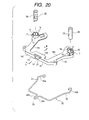
- a core 11 of a steering wheel is formed from a metallic material, and a boss portion 12 in which a steering shaft is securely fitted and three through holes 13 are formed in the center and outer circumferential edge positions of the core.
- An annular holding member 14 formed of a synthetic resin is mounted on a lower surface of the core 11 with a plurality of bolts, not shown.
- three cylindrical portions 15 are provided on an upper surface of the holding member 14 at circumferential edge portions in such a manner as to protrude therefrom.
- a plurality of slits 16 are formed in an upper edge of each of the cylindrical portions and a pawl 17 is provided at a circumferential position around an upper end of each of the cylindrical portions in such a manner as to protrude therefrom, as well.
- a rib 19 is formed around an outer circumference of the holding member 14 in such a manner as to protrude from a lower surface thereof, and a holding portion 20 is formed on an internal surface of the rib 19 at a portion confronting each cylindrical portion 15.
- a dislocation preventing portion 21 is formed on a lower edge of the rib 19 at a position adjacent to each cylindrical portion 15 in such a manner as to protrude inwardly.
- an opening 22 is formed in the side of the rib 19 at a position adjacent to the front cylindrical portion 15.
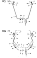
- a locking wire 23 as a locking body is mounted on a bottom of the holding member 14 in such a manner as to be moved and displaced back and forth.
- this locking wire 23 is formed of a single resilient metallic wire which is formed into substantially a trapezoidal ring-like shape which is partially opened. Then, this locking wire 23 is mounted and disposed at a lock position P1 constituting a lockable status on the internal surface of the rib 19 on the holding member 14 in a state in which the locking wire is diametrically contracted overall, and the dislocation of the locking wire 23 so disposed is then prevented by the dislocation preventing portions 21.
- the locking wire 23 When the locking wire 23 is mounted as described above, the locking wire 23 is brought into contact with the holding portions 20, whereby three locking portions 23a on the locking wire 23 are disposed so as to extend over the passage holes 18, respectively, in a direction in which the locking portions 23a intersect with axes of the passage holes 18 along the rib 19.
- An operating portion 24 is formed at a front portion of the locking wire 23 in such a manner as to protrude therefrom, so that the operating portion 24 protrudes forward through the opening 22 when the locking wire 23 is mounted on the holding member 14.
- concave recess portions 25 are formed both sides of the locking wire 23 at positions adjacent to the pair of rear locking portions 23a, respectively.
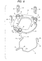
- the locking wire 23 is moved and displaced from the front lock position P1 to a rear release position P2 constituting the removable status. Then, the locking wire 23 is contracted diametrically inwardly at open ends thereof against its resiliency as shown by chain lines in Fig. 5 along internal surfaces of the hook portions 30 in the pair of rear pins 29 and the holding portions 20.
- the hook portions 30 in the pair of rear pins 29 are separated away from the locking portions 23a and are disposed so as to confront the recess portions 25, and the hook portion 30 in the front pin 29 is also separated away from the locking portion 23a, whereby the engagement between the locking wire 23 and the hook portions 30 at the three locking locations is released at one time.
- an inverted angle-like engagement projection 26 acting as a changeover member is formed on a lower surface of a front internal portion of the holding member 14, and a release portion 27 acting as a return means is formed continuously with an upper portion of the engagement projection 26.
- the front locking portion 23a of the locking wire 23 is constructed to be brought into engagement with the engagement projection 26 when the locking wire 23 is moved to the rear release position P2, whereby the locking wire 23 is locked and held at the release position P2.
- the release portion 27 when the release portion 27 is operated to be lifted up from that status so that the engagement projection 26 is moved upwardly, the locking portion 23a of the locking wire 23 is release from the engagement with the engagement projection 26.
- the locking wire 23 is then moved to return from the rear release position P2 to the front lock position P1 by virtue of its own resiliency.
- the locking wire 23 is disposed at the front lock position P1 in the holding member 14.
- the three pins 29 provided on the bottom surface of the air bag module 28 so as to protrude therefrom are allowed to pass through the three passage holes 18 in the holding member 14 mounted on the core 11, respectively.
- the locking wire 23 disposed at the lock position P1 on the lower surface of the holding member 14 is brought into a resilient engagement with the hook portions 30 in the pins 29 from inside within the respective passage holes 18, whereby the air bag module 28 is locked and held to the core 11 at the three locking locations.
- the air bag module 28 can be mounted easily and quickly on the steering wheel through a one-touch or single operation.
- the operating portion 24 protruding forward from the opening 22 in the holding member 14 is operated to be pushed.
- the operating portion 24 continues to be operated and pushed until the locking portion 23a of the locking wire 23 rides over the engagement projection 26, whereby the locking wire 23 is changed over from the lock position P1 to the release position P2 so as to be disposed at the latter position, the locking wire 23 being thus held to the release position P2.
- the locking wire 23 is contracted diametrically inwardly at the open ends thereof against its own resiliency, whereby the engagement between the locking portions 23a of the locking wire 23 and the hook portions 30 in the pins 29 is released at one time at the three locking locations.
- the pins 29 of the air bag module 28 are drawn out of the passage holes 18 in the holding member 14, respectively, whereby the air bag module 28 can be removed from the core 11 of the steering wheel.
- the air bag module 28 since the air bag module 28 is released from the locked state through a one-touch or single operation with the locking wire 23 being held at the release position P2, the air bag module 28 can be removed easily from the core 11 of the steering wheel.
- the release portion 27 is operated to be lifted up so as to move the engagement projection 26 upwardly. Then, the locking portion 23a of the locking wire 23 is released from the engagement with the engagement projection 26, and the locking wire 23 is moved to automatically return from the rear release position P2 to the front lock position P1 by virtue of its own resiliency.
- the pins 29 of the air bag module 28 are allowed to pass through the passage holes 18 in the holding member 14, respectively, so that the locking wire 23 is brought into a resilient engagement with the hook portions 30 in the pins 29.
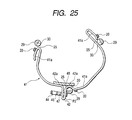
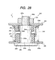
- the snap-lock mechanism 250 illustrated as the snap-lock mechanism 250 is the snap-lock mechanism of a type in which the operating portion 254a on the wire 254 is pushed and pulled to change over the wire 254 between the lock position and the release position so as to dispose the wire 254 thereat.
- a type of snap-lock mechanism may be used in which the operating portion 254a on the wire 254 is rotated along the side wall portion 218b of the fixing plate 218 to thereby change over the wire 254 between the lock position and the release position so as to dispose the wire 254 thereat.
- the number of pin portions 251 may be set optionally depending upon the size and configuration of the air bag module 220 provided that at least a pair is provided.
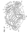
- the edge portion 226e of the stationary contact plate 226 is constructed to be brought into contact with the stepped portions 219 on the four spoke portions, respectively, in the embodiment, the stepped portions 219 may be constructed to be provided only on any three of the four spoke portions 213.
- the horn switch mechanism 240 is constructed to be provided with the coil spring 245 in the embodiment, for example, a leaf spring, a volute spring or the like may be provided instead of the coil spring 245.
- the stationary contact plate 226 is formed so as to have substantially the U-shaped cross section in the embodiment, the stationary contact plate 226 may not be formed so as to have the U-shaped cross section in the event that the stationary contact plate 226 is not deformed by the biasing force of the coil spring 245 when the horn is activated or that the amount of deformation thereof falls within an allowable range.
- edge portion 226e of the stationary contact plate 226 is constructed to be brought into abutment with the stepped portions 219 on the spoke portions 213 in the embodiment, there may be provided no such stepped portion 219 in the event that the stationary contact plate 226 is not deformed by the biasing force of the coil spring 245 when the horn is activated or that the amount of deformation thereof falls within an allowable range.
- the fixing plate 218 may be disposed outwardly of the spoke portion cores 215c.
- the passage holes through which the pin portions 251 are allowed to pass are formed in the boss portion core 215b on the steering wheel main body 214, while the fixing plate 218 functions only to hold the wire 254.
- the pin portions 251 are provided on the pin supporting portions 226c of the stationary contact plate 226 with the passage holes 253 being formed in the fixing plate 218 in the embodiment, the pin portions 251 may be provided on a confronting surface of the steering main body 214 which confronts the bottom of the air bag module 220 in such a manner as to protrude therefrom with the passage holes 253 being formed on the bottom of the air bag module 220.
- the air bag module 220 may be fixed to the steering wheel main body 214 at the pin supporting portions 226c of the stationary contact plate 226 via the snap-lock mechanism 250 in the embodiment, the air bag module 220 may be fixed to the steering wheel main body 214 at the side wall portions 226d of the stationary contact plate 226 constituting the external surface thereof via the snap-lock mechanism 250.
- fixing plate 218 a plurality of fixing plates 218 and locking bodies such as short wires may be provided for each portion where the snap-lock mechanism 250 is provided, and the plurality of fixing plates and locking bodies may be formed integrally.
- the air bag module 220 is constructed to be fixed to the steering wheel main body 214 through the engagement between the pin portions 251 having the hook portions 252 and the wire 254 in the embodiment, the air bag module 220 may be constructed to be fixed to the steering wheel main body 214 through engagement between clips having locking pawls and passage holes through which the locking clips are allowed to pass.
- the present invention is constructed as has been described heretofore, the invention can provide the following advantages.
- the removal of the air bag module can easilybe implemented while preventing the abrupt return of the locking body to the lockable status.
- the locking body Since the locking body is held in the removable status when the air bag module is removed from the steering wheel, the removal of the air bag module can be implemented quickly and more easily.
- the air bag module When the air bag module is re-mounted on the steering wheel, the air bag module can be re-mounted quickly and easily.
- the number of parts can be reduced. Moreover, when the air bag module is removed, the single locking body only has to be changed over to and displaced at the removable status, whereby the removal of the air bag module from the steering wheel can be implemented more quickly and easily.
- the engagement of the hook portions with the locking body at the plurality of locking locations can be released at one time. Consequently, the removal of the air bag module can be carried out more quickly and easily.
- the locking body can automatically be returned to the lockable status by virtue of its own resiliency. Consequently, when the air bag module is re-mounted on the steering wheel, the air bag module can be mounted on the steering wheel more quickly and easily.
- the changeover member can be constructed with the simple construction without increasing the number of parts.
- the locking body can be held at the release position in a more ensured fashion by brining the operating portion into engagement with the engagement portion.
- At least part of the plurality of passage holes and changeover member can easily be formed in and on the holding member formed of a synthetic resin or the like. Then, the locking body can simply be mounted on the core of the steering wheel via the holding member.
- the engagement of the hook portions with the locking body at the plurality of locking locations can be released at one time, whereby the air bag module can easily be removed from the steering wheel.
- the locking body is diametrically contracted or expanded at the release position, whereby the engagement between the hook portions and the locking body at the plurality of locking locations can easily be released.
- the recess portions on the locking body are allowed to confront the hook portions, respectively, by displacing the locking wire to the release position over a small displacement distance, whereby the engagement between the hook portions and the locking body can easily be released.
- the locking body can easily be displaced to the release position by operating the operating portion.
- the locking body can be held in the mounted status in which the locking body confronts the respective passage holes by the holding portions in an ensured fashion. Then, when the hook portions in the pins are brought into engagement with the locking body, respectively, the locking body is separated away from the holding portions and is brought into a press engagement with the hook portions by virtue of its own resiliency, whereby the air bag module can be locked and held rigidly onto the steering wheel.
- the air bag module can be locked and held stably onto the steering wheel at three or more locking locations.
- the plurality of passage holes can easily be formed in the holding member formed from a a synthetic resin, and the locking body can simply be mounted on the holding member.
- the locking body When the locking body is operated so as to be moved to the release position, the locking body is contracted diametrically inwardly of the respective pins, whereby the engagement between the locking body and the respective hook portions can easily be released.
- the locking body When the locking body is operated so as to be moved to the release position, the locking body is contracted diametrically outwardly of the respect pins, whereby the engagement between the locking body and the respective hook portions can easily be released.
- the engagement between the hook portions and the locking body at the plurality of locking locations can be released at one time, whereby the air bag module can easily be removed from the steering wheel.
- the locking body When the operating portion is operated, the locking body can easily be rotated to the release position.
- the locking body can be held by the holding portions in the mounted status where the locking body is allowed to confront the respective passage holes in an ensured fashion. Then, when the hook portions in the pins are brought into engagement with the locking body, respectively, the locking body is separated away from the holding portions and is brought into a press engagement with the hook portions, respectively, whereby the air bag module can rigidly be locked and held onto the steering wheel.
- the air bag module can stably be locked and held onto the steering wheel at three or more locking locations.
- the plurality of passage holes can easily be formed in the holding member formed from the synthetic resin or the like, and the locking body can simply be mounted on the holding member.
- the air bag module can be mounted on and removed from the steering wheel easily and smoothly.
- the stroke of the horn switch mechanism can be corrected to the set value with ease.
- the air bag module can be fixed to the steering wheel in the stable condition.
- the air bag module can be mounted to the steering wheel with ease and in the stable condition using the snap-lock mechanism having the simple construction.
- the pin portions can be prevented from being inclined, whereby there occurs no case where the air bag is supported unstably.
- the strength of the stationary plate itself can be increased, whereby even if the driver or passenger of the vehicle strongly presses against the air bag module, the deformation of the stationary plate by the pressing force can be prevented preferably.
- the stationary plate can be disposed relative to the steering wheel main body in the stable condition.
Landscapes
- Engineering & Computer Science (AREA)
- Mechanical Engineering (AREA)
- Physics & Mathematics (AREA)
- Acoustics & Sound (AREA)
- Air Bags (AREA)
Priority Applications (1)
| Application Number | Priority Date | Filing Date | Title |
|---|---|---|---|
| EP04001627A EP1418095B1 (fr) | 2000-06-27 | 2001-06-25 | Volant avec sac gonflable |
Applications Claiming Priority (10)
| Application Number | Priority Date | Filing Date | Title |
|---|---|---|---|
| JP2000193461 | 2000-06-27 | ||
| JP2000193461A JP2002002433A (ja) | 2000-06-27 | 2000-06-27 | エアバッグモジュールの取付構造 |
| JP2000196553A JP4269492B2 (ja) | 2000-06-29 | 2000-06-29 | エアバッグモジュールの取付構造 |
| JP2000196553 | 2000-06-29 | ||
| JP2000198184 | 2000-06-30 | ||
| JP2000198184A JP2002012112A (ja) | 2000-06-30 | 2000-06-30 | エアバッグモジュールの取付構造 |
| JP2001021280A JP4719983B2 (ja) | 2001-01-30 | 2001-01-30 | エアバッグ装置付きステアリングホイール |
| JP2001021280 | 2001-01-30 | ||
| JP2001023088 | 2001-01-31 | ||
| JP2001023088A JP4538964B2 (ja) | 2001-01-31 | 2001-01-31 | エアバッグモジュールの取付構造 |
Related Child Applications (1)
| Application Number | Title | Priority Date | Filing Date |
|---|---|---|---|
| EP04001627A Division EP1418095B1 (fr) | 2000-06-27 | 2001-06-25 | Volant avec sac gonflable |
Publications (3)
| Publication Number | Publication Date |
|---|---|
| EP1167132A2 true EP1167132A2 (fr) | 2002-01-02 |
| EP1167132A3 EP1167132A3 (fr) | 2002-04-17 |
| EP1167132B1 EP1167132B1 (fr) | 2004-06-09 |
Family
ID=27531592
Family Applications (2)
| Application Number | Title | Priority Date | Filing Date |
|---|---|---|---|
| EP04001627A Expired - Lifetime EP1418095B1 (fr) | 2000-06-27 | 2001-06-25 | Volant avec sac gonflable |
| EP01115324A Expired - Lifetime EP1167132B1 (fr) | 2000-06-27 | 2001-06-25 | Structure de montage pour un module d'air-bag |
Family Applications Before (1)
| Application Number | Title | Priority Date | Filing Date |
|---|---|---|---|
| EP04001627A Expired - Lifetime EP1418095B1 (fr) | 2000-06-27 | 2001-06-25 | Volant avec sac gonflable |
Country Status (3)
| Country | Link |
|---|---|
| US (1) | US6554312B2 (fr) |
| EP (2) | EP1418095B1 (fr) |
| DE (2) | DE60103699T2 (fr) |
Cited By (12)
| Publication number | Priority date | Publication date | Assignee | Title |
|---|---|---|---|---|
| DE20206310U1 (de) | 2002-04-16 | 2002-08-08 | TAKATA-PETRI AG, 63743 Aschaffenburg | Kraftfahrzeugbaugruppe |
| EP1410959A1 (fr) * | 2002-10-15 | 2004-04-21 | TRW Automotive Safety Systems GmbH | Ensemble avec un corps de base pour un volant et une module coussin gonflable |
| EP1464550A1 (fr) * | 2003-04-02 | 2004-10-06 | Autoliv Development Aktiebolag | Amélioration dans ou par rapport à une unité d'airbag montée sur un siège |
| EP1354770A3 (fr) * | 2002-03-01 | 2004-10-27 | Autoliv Development AB | Système de fixation pour un airbag |
| EP1527961A1 (fr) * | 2003-10-27 | 2005-05-04 | TRW Automotive Safety Systems GmbH | Système de retenue avec coussin gonflable |
| WO2007067122A1 (fr) * | 2005-12-08 | 2007-06-14 | Autoliv Development Ab | Appareillage de montage pour le montage d'un module airbag |
| EP1800970A1 (fr) * | 2005-12-21 | 2007-06-27 | TRW Automotive Safety Systems GmbH | Module de sac de sécurité gonflable |
| EP2554439A4 (fr) * | 2010-03-30 | 2013-08-14 | Ashimori Ind Co Ltd | Dispositif de coussin de sécurité gonflable |
| GB2512892A (en) * | 2013-04-10 | 2014-10-15 | Ford Global Tech Llc | A method and apparatus for attaching a driver airbag module to a steering wheel |
| FR3083189A1 (fr) * | 2018-06-29 | 2020-01-03 | Autoliv Development Ab | Dispositif de montage amovible d'un module de coussin gonflable |
| CN111828751A (zh) * | 2020-07-13 | 2020-10-27 | 郝中亮 | 一种纳米复合纤维管 |
| WO2021018686A1 (fr) * | 2019-07-29 | 2021-02-04 | Autoliv Development Ab | Dispositif de montage amovible d'un module de coussin gonflable sur un volant |
Families Citing this family (64)
| Publication number | Priority date | Publication date | Assignee | Title |
|---|---|---|---|---|
| US6830263B2 (en) * | 2002-02-08 | 2004-12-14 | Key Safety Systems, Inc. | Method for attaching an airbag module |
| DE20204461U1 (de) * | 2002-03-20 | 2002-07-25 | TRW Automotive Safety Systems GmbH & Co. KG, 63743 Aschaffenburg | Baugruppe mit Rastelementen |
| US6874808B2 (en) * | 2002-09-20 | 2005-04-05 | Delphi Technologies, Inc. | Apparatus and method for maintaining a uniform gap between an airbag module and its surrounding structure |
| US6783150B2 (en) * | 2002-09-30 | 2004-08-31 | Trw Vehicle Safety Systems Inc. | Snap together mounting of an air bag module and a vehicle steering wheel |
| US6951348B2 (en) * | 2002-10-24 | 2005-10-04 | Autoliv Asp, Inc. | Rigid airbag plate attachment system |
| DE20219284U1 (de) * | 2002-12-12 | 2003-02-20 | Trw Automotive Safety Sys Gmbh | Gassackmodul |
| US7059631B2 (en) * | 2003-04-29 | 2006-06-13 | Toyoda Gosei Co., Ltd. | Method and apparatus for coupling a driver's side airbag to a steering wheel |
| US20050046153A1 (en) * | 2003-08-27 | 2005-03-03 | Depottey Timothy A. | Airbag inflator mounting apparatus and method |
| DE202004000953U1 (de) * | 2004-01-22 | 2004-05-27 | Trw Automotive Safety Systems Gmbh | Fahrzeuglenkrad |
| US7055854B2 (en) * | 2004-03-03 | 2006-06-06 | Autoliv Asp, Inc. | Snap-in castanet airbag module for a vehicular steering wheel |
| GB2412093A (en) * | 2004-03-16 | 2005-09-21 | Autoliv Dev | Steering wheel unit with rotation locking element |
| US7556281B2 (en) * | 2004-03-16 | 2009-07-07 | Toyoda Gosei Co., Ltd. | Stamped airbag retention members and method of airbag assembly |
| DE102004033295A1 (de) * | 2004-07-08 | 2006-02-02 | Autoliv Development Ab | Gassack-Modul |
| US7510209B2 (en) * | 2004-09-10 | 2009-03-31 | Delphi Technologies, Inc. | Airbag module with integral locking mechanism and method of making |
| US7533897B1 (en) * | 2005-02-16 | 2009-05-19 | Key Safety Systems, Inc. | Method and apparatus for securing an air bag |
| JP4797584B2 (ja) * | 2005-03-16 | 2011-10-19 | タカタ株式会社 | エアバッグ装置付きステアリングホイール |
| US7422236B2 (en) * | 2005-03-21 | 2008-09-09 | Delphi Technologies, Inc. | Apparatus and method for providing a horn contact mechanism |
| US7293794B2 (en) * | 2005-03-31 | 2007-11-13 | Tk Holdings Inc. | Cover attachment |
| KR100657662B1 (ko) * | 2005-10-06 | 2006-12-14 | 기아자동차주식회사 | 차량의 운전석 에어백 모듈 조립장치 |
| US7556282B2 (en) * | 2006-03-09 | 2009-07-07 | Toyoda Gosei Co. Ltd. | Steering wheel assembly |
| DE102006041734B4 (de) * | 2006-09-01 | 2010-07-29 | Takata-Petri Ag | Vorrichtung zur Befestigung einer Airbageinheit in einer Baugruppe eines Kraftfahrzeugs, insbesondere in einem Lenkrad, durch Verrasten |
| WO2009029203A1 (fr) * | 2007-08-27 | 2009-03-05 | Key Safety Systems, Inc. | Module de coussin de sécurité gonflable pour genou |
| DE102008013526B4 (de) * | 2008-03-07 | 2012-02-02 | Autoliv Development Ab | Sicherheitsanordnung sowie Verfahren zur Herstellung einer Sicherheitsanordnung |
| US8256797B2 (en) * | 2008-09-16 | 2012-09-04 | Toyoda Gosei Co., Ltd. | Steering wheel with airbag device and method for assembling the same |
| JP5353212B2 (ja) * | 2008-12-02 | 2013-11-27 | タカタ株式会社 | 運転席用エアバッグ装置の取付構造及びステアリングホイール |
| DE102009050893A1 (de) * | 2009-10-27 | 2011-04-28 | Autoliv Development Ab | Gassackmodul |
| JP5497485B2 (ja) | 2010-03-04 | 2014-05-21 | 芦森工業株式会社 | エアバッグ装置 |
| JP5432011B2 (ja) | 2010-03-12 | 2014-03-05 | 芦森工業株式会社 | エアバッグ装置の取付部構造 |
| JP5206756B2 (ja) * | 2010-09-30 | 2013-06-12 | 豊田合成株式会社 | エアバッグ装置付きステアリングホイール |
| US8376398B2 (en) * | 2011-07-12 | 2013-02-19 | Tk Holdings Inc. | Airbag and horn switch module and method of assembly of the module |
| DE102012002722A1 (de) * | 2011-09-15 | 2013-03-21 | Trw Automotive Safety Systems Gmbh | Verfahren und Vorrichtung zur Serienfertigung einer Fahrzeugbaugruppe, Lagereinheit, Fahrzeuglenkrad sowie Hupenmodul für eine Lenkradbaugruppe sowie Lenkradbaugruppe |
| DE102011118090B4 (de) * | 2011-11-10 | 2015-08-06 | Autoliv Development Ab | Lenkradeinheit |
| JP5765284B2 (ja) * | 2012-03-30 | 2015-08-19 | 豊田合成株式会社 | ステアリングホイールの制振構造 |
| CN102765416A (zh) * | 2012-07-03 | 2012-11-07 | 重庆长安汽车股份有限公司 | 转向盘盖板安装柱及带有该安装柱的转向盘盖板 |
| JP5705809B2 (ja) * | 2012-09-28 | 2015-04-22 | 本田技研工業株式会社 | 係止構造、装着部材及びエアバッグ装置 |
| CN103192787B (zh) * | 2013-01-07 | 2015-08-05 | 浙江吉利汽车研究院有限公司杭州分公司 | 一种带气囊的方向盘结构 |
| JP6185798B2 (ja) * | 2013-05-07 | 2017-08-23 | 日本プラスト株式会社 | ステアリングホイール |
| DE102013008818B3 (de) * | 2013-05-25 | 2014-10-16 | Autoliv Development Ab | Lenkradeinheit |
| DE102013011811A1 (de) * | 2013-07-16 | 2015-01-22 | Trw Automotive Safety Systems Gmbh | Gassackbaugruppe und lenkradbaugruppe |
| GB2540254B (en) * | 2014-03-18 | 2018-02-28 | Nihon Plast Co Ltd | Steering wheel |
| DE102014006300A1 (de) * | 2014-05-02 | 2015-08-06 | Autoliv Development Ab | Lenkradeinheit mit einem Lenkradkörper und einem gegen den Lenkradkörper niederdrückbaren Gassackgehäuse |
| US9914420B2 (en) * | 2015-04-13 | 2018-03-13 | GM Global Technology Operations LLC | Driver airbag module new lock spring design proposal for visual verification of module's robust attachment to the steering wheel |
| US9783147B2 (en) * | 2015-08-18 | 2017-10-10 | Key Safety Systems, Inc. | Driver air bag with snap-in attachment mechanism |
| EP3178707B1 (fr) * | 2015-12-08 | 2018-07-18 | Autoliv Development AB | Volant de direction |
| DE102016005020B4 (de) * | 2016-04-26 | 2019-08-14 | Dalphi Metal Espana, S.A. | Gassackeinheit und Fahrzeuginsassensicherheitssystem mit einer solchen Gassackeinheit sowie Herstellungsverfahren |
| WO2018044254A1 (fr) * | 2016-08-29 | 2018-03-08 | Trw Vehicle Safety Systems Inc. | Système de vérification de montage de coussin de sécurité gonflable conducteur |
| DE102017102463A1 (de) | 2017-02-08 | 2018-08-09 | Trw Automotive Safety Systems Gmbh | Lagereinheit, lenkradbaugruppe sowie verfahren zur herstellung einer fahrzeugbaugruppe |
| JP6835633B2 (ja) * | 2017-03-10 | 2021-02-24 | 芦森工業株式会社 | ステアリングハンドル構造 |
| CN107089213B (zh) * | 2017-03-21 | 2019-03-08 | 浙江零跑科技有限公司 | 一种乘员侧安全气囊固定结构 |
| US11034374B2 (en) * | 2017-08-10 | 2021-06-15 | Toyoda Gosei Co., Ltd. | Steering wheel |
| DE102017119886A1 (de) * | 2017-08-30 | 2019-02-28 | Trw Automotive Safety Systems Gmbh | Federelement zur befestigung eines gassackmoduls an einem fahrzeuglenkrad sowie lenkradbaugruppe mit einem solchen federelement |
| EP3741648B1 (fr) * | 2018-01-19 | 2024-04-24 | Autoliv Development AB | Volant de direction |
| DE102018112224A1 (de) * | 2018-05-22 | 2019-11-28 | Trw Automotive Safety Systems Gmbh | Fahrzeuglenkrad sowie Lenkradbaugruppe mit einem solchen Fahrzeuglenkrad |
| US10926698B2 (en) * | 2018-12-17 | 2021-02-23 | Key Safety Systems, Inc. | Integrated steering wheel, vibration absorber, and driver airbag |
| DE202018107231U1 (de) * | 2018-12-18 | 2020-03-19 | Trw Automotive Safety Systems Gmbh | Lenkvorrichtungsbaugruppe für ein Kraftfahrzeug |
| JP7184024B2 (ja) * | 2019-03-29 | 2022-12-06 | 豊田合成株式会社 | ホーンスイッチ体を備えたエアバッグ装置 |
| KR102693552B1 (ko) * | 2019-04-11 | 2024-08-08 | 현대모비스 주식회사 | 운전석 에어백장치 |
| US11383665B2 (en) * | 2019-12-10 | 2022-07-12 | Autoliv Asp, Inc. | Driver airbag module coupling assemblies |
| FR3112110B1 (fr) * | 2020-07-03 | 2022-07-15 | Autoliv Dev | Volant de véhicule équipé d’un module de sécurité |
| KR102855730B1 (ko) * | 2020-07-17 | 2025-09-04 | 현대모비스 주식회사 | 스티어링 휠과 에어백 모듈의 결합 장치 |
| JP7302561B2 (ja) * | 2020-09-14 | 2023-07-04 | 豊田合成株式会社 | エアバッグ装置の取付機構 |
| CN112863088B (zh) * | 2020-12-30 | 2023-01-06 | 武汉楚客科技有限公司 | 一种气体检测仪的远程无线式声光报警器 |
| CN116061805B (zh) * | 2021-11-04 | 2026-01-27 | 延锋汽车智能安全系统有限责任公司 | 车辆方向盘 |
| KR20240033489A (ko) * | 2022-09-05 | 2024-03-12 | 현대자동차주식회사 | 스티어링휠과, 그 스티어링휠의 댐퍼유닛 |
Family Cites Families (12)
| Publication number | Priority date | Publication date | Assignee | Title |
|---|---|---|---|---|
| US5421607A (en) * | 1994-06-15 | 1995-06-06 | General Motors Corporation | Air bag attachment mechanism |
| US5470100A (en) * | 1994-08-25 | 1995-11-28 | General Motors Corporation | Air bag module inflator retainer |
| DE19503816B4 (de) | 1995-02-06 | 2007-03-22 | Volkswagen Ag | Anordnung zur Befestigung eines aus einem Gehäuseboden und einem Gehäusedeckel bestehenden Gehäuses im Lenkrad |
| US5636858A (en) * | 1995-05-05 | 1997-06-10 | General Motors Corporation | Air bag module |
| DE19724029A1 (de) | 1997-06-06 | 1998-12-24 | Takata Europ Gmbh | Airbag-Vorrichtung |
| US6092832A (en) * | 1998-03-04 | 2000-07-25 | General Motors Corporation | Air bag module mounting mechanism and method of making |
| DE29806933U1 (de) * | 1998-04-17 | 1998-07-02 | Hazet-Werk Hermann Zerver Gmbh & Co Kg, 42857 Remscheid | Handwerkzeug |
| DE19858691B4 (de) * | 1998-12-18 | 2010-01-07 | Delphi Automotive Systems Deutschland Gmbh | Luftsackmodul für Kraftfahrzeuge |
| FR2790044B1 (fr) * | 1999-02-19 | 2001-05-25 | Gersteen Iso Delta | Element de volant de direction de vehicule et volant comportant cet element |
| ES1045448Y (es) * | 1999-11-23 | 2001-03-01 | Dalphi Metal Espana Sa | Disposicion de fijacion rapida perfeccionada del modulo airbag con el volante. |
| US6276711B1 (en) * | 2000-03-27 | 2001-08-21 | Breed Automotive Technology, Inc. | Quick disconnect feature for snap-in driver air bag module |
| US6325408B1 (en) * | 2000-05-15 | 2001-12-04 | Breed Automotive Technology, Inc. | Air bag attachment arrangement |
-
2001
- 2001-06-25 EP EP04001627A patent/EP1418095B1/fr not_active Expired - Lifetime
- 2001-06-25 EP EP01115324A patent/EP1167132B1/fr not_active Expired - Lifetime
- 2001-06-25 DE DE60103699T patent/DE60103699T2/de not_active Expired - Lifetime
- 2001-06-25 DE DE60119176T patent/DE60119176T2/de not_active Expired - Lifetime
- 2001-06-27 US US09/891,291 patent/US6554312B2/en not_active Expired - Lifetime
Cited By (22)
| Publication number | Priority date | Publication date | Assignee | Title |
|---|---|---|---|---|
| EP1354770A3 (fr) * | 2002-03-01 | 2004-10-27 | Autoliv Development AB | Système de fixation pour un airbag |
| EP1354772A3 (fr) * | 2002-04-16 | 2004-02-04 | Takata-Petri AG | Sous-ensemble de véhicule automobile |
| DE20206310U1 (de) | 2002-04-16 | 2002-08-08 | TAKATA-PETRI AG, 63743 Aschaffenburg | Kraftfahrzeugbaugruppe |
| US7118124B2 (en) | 2002-04-16 | 2006-10-10 | Takata-Petri Ag | Motor vehicle subassembly |
| US7097197B2 (en) | 2002-10-15 | 2006-08-29 | Trw Automotive Safety Systems Gmbh | Assembly of a steering wheel base body and gas bag module |
| EP1410959A1 (fr) * | 2002-10-15 | 2004-04-21 | TRW Automotive Safety Systems GmbH | Ensemble avec un corps de base pour un volant et une module coussin gonflable |
| EP1464550A1 (fr) * | 2003-04-02 | 2004-10-06 | Autoliv Development Aktiebolag | Amélioration dans ou par rapport à une unité d'airbag montée sur un siège |
| US7267363B2 (en) | 2003-04-02 | 2007-09-11 | Autoliv Development Ab | Air-bag unit mounted on a seat |
| EP1527961A1 (fr) * | 2003-10-27 | 2005-05-04 | TRW Automotive Safety Systems GmbH | Système de retenue avec coussin gonflable |
| US7469921B2 (en) | 2003-10-27 | 2008-12-30 | Trw Automotive Safety Systems Gmbh | Gas bag restraint system |
| WO2007067122A1 (fr) * | 2005-12-08 | 2007-06-14 | Autoliv Development Ab | Appareillage de montage pour le montage d'un module airbag |
| GB2433234A (en) * | 2005-12-08 | 2007-06-20 | Autoliv Dev | A mounting arrangement for an airbag |
| US7789415B2 (en) | 2005-12-08 | 2010-09-07 | Autoliv Development Ab | Mounting arrangement for mounting an air-bag module |
| EP1800970A1 (fr) * | 2005-12-21 | 2007-06-27 | TRW Automotive Safety Systems GmbH | Module de sac de sécurité gonflable |
| EP2554439A4 (fr) * | 2010-03-30 | 2013-08-14 | Ashimori Ind Co Ltd | Dispositif de coussin de sécurité gonflable |
| GB2512892A (en) * | 2013-04-10 | 2014-10-15 | Ford Global Tech Llc | A method and apparatus for attaching a driver airbag module to a steering wheel |
| FR3083189A1 (fr) * | 2018-06-29 | 2020-01-03 | Autoliv Development Ab | Dispositif de montage amovible d'un module de coussin gonflable |
| WO2021018686A1 (fr) * | 2019-07-29 | 2021-02-04 | Autoliv Development Ab | Dispositif de montage amovible d'un module de coussin gonflable sur un volant |
| FR3099437A1 (fr) * | 2019-07-29 | 2021-02-05 | Autoliv Development Ab | Dispositif de montage amovible d’un module de coussin gonflable sur un volant |
| US11766980B2 (en) | 2019-07-29 | 2023-09-26 | Autoliv Development Ab | Device for removably mounting an airbag module on a steering wheel |
| CN111828751A (zh) * | 2020-07-13 | 2020-10-27 | 郝中亮 | 一种纳米复合纤维管 |
| CN111828751B (zh) * | 2020-07-13 | 2022-05-13 | 郝中亮 | 一种纳米复合纤维管 |
Also Published As
| Publication number | Publication date |
|---|---|
| EP1418095B1 (fr) | 2006-04-26 |
| EP1418095A1 (fr) | 2004-05-12 |
| DE60119176T2 (de) | 2007-03-29 |
| EP1167132A3 (fr) | 2002-04-17 |
| DE60103699D1 (de) | 2004-07-15 |
| DE60119176D1 (de) | 2006-06-01 |
| US20010054810A1 (en) | 2001-12-27 |
| US6554312B2 (en) | 2003-04-29 |
| EP1167132B1 (fr) | 2004-06-09 |
| DE60103699T2 (de) | 2005-06-16 |
Similar Documents
| Publication | Publication Date | Title |
|---|---|---|
| EP1418095B1 (fr) | Volant avec sac gonflable | |
| US11034374B2 (en) | Steering wheel | |
| KR102610029B1 (ko) | 스티어링 휠 | |
| US6419261B1 (en) | Airbag apparatus | |
| JP2010132035A (ja) | 運転席用エアバッグ装置の取付構造及びステアリングホイール | |
| US10196028B2 (en) | Steering wheel | |
| US6639160B2 (en) | Steering switch assembly structure | |
| EP3741647B1 (fr) | Volant de direction | |
| US5647610A (en) | Steering wheel with air bag device | |
| US6595083B2 (en) | Steering wheel | |
| US5720494A (en) | Steering wheel with air bag device | |
| US7261317B2 (en) | Airbag system | |
| JP2011213250A (ja) | ハンドル | |
| JP2004322931A (ja) | エアバッグ装置付きステアリングホイール | |
| JP4719983B2 (ja) | エアバッグ装置付きステアリングホイール | |
| US20190299906A1 (en) | Airbag device | |
| EP2687411B1 (fr) | Dispositif de coussin de sécurité gonflable et volant | |
| JP5582846B2 (ja) | ハンドル | |
| US5957484A (en) | Airbag tear seam | |
| JP5777903B2 (ja) | エアバッグ装置 | |
| US7007969B2 (en) | Airbag module | |
| JP2004256078A (ja) | エアバッグ装置付きステアリングホイール | |
| US20170136662A1 (en) | Method of manufacturing folded body of airbag | |
| JP2005041442A (ja) | エアバッグ装置付きステアリングホイール | |
| JP4036122B2 (ja) | エアバッグ装置を備えたステアリングホイール |
Legal Events
| Date | Code | Title | Description |
|---|---|---|---|
| PUAI | Public reference made under article 153(3) epc to a published international application that has entered the european phase |
Free format text: ORIGINAL CODE: 0009012 |
|
| 17P | Request for examination filed |
Effective date: 20010625 |
|
| AK | Designated contracting states |
Kind code of ref document: A2 Designated state(s): AT BE CH CY DE DK ES FI FR GB GR IE IT LI LU MC NL PT SE TR Kind code of ref document: A2 Designated state(s): DE FR GB |
|
| AX | Request for extension of the european patent |
Free format text: AL;LT;LV;MK;RO;SI |
|
| PUAL | Search report despatched |
Free format text: ORIGINAL CODE: 0009013 |
|
| AK | Designated contracting states |
Kind code of ref document: A3 Designated state(s): AT BE CH CY DE DK ES FI FR GB GR IE IT LI LU MC NL PT SE TR |
|
| AX | Request for extension of the european patent |
Free format text: AL;LT;LV;MK;RO;SI |
|
| AKX | Designation fees paid |
Free format text: DE FR GB |
|
| 17Q | First examination report despatched |
Effective date: 20030617 |
|
| GRAP | Despatch of communication of intention to grant a patent |
Free format text: ORIGINAL CODE: EPIDOSNIGR1 |
|
| GRAS | Grant fee paid |
Free format text: ORIGINAL CODE: EPIDOSNIGR3 |
|
| GRAA | (expected) grant |
Free format text: ORIGINAL CODE: 0009210 |
|
| AK | Designated contracting states |
Kind code of ref document: B1 Designated state(s): DE FR GB |
|
| REG | Reference to a national code |
Ref country code: GB Ref legal event code: FG4D |
|
| REF | Corresponds to: |
Ref document number: 60103699 Country of ref document: DE Date of ref document: 20040715 Kind code of ref document: P |
|
| REG | Reference to a national code |
Ref country code: IE Ref legal event code: FG4D |
|
| ET | Fr: translation filed | ||
| REG | Reference to a national code |
Ref country code: IE Ref legal event code: MM4A |
|
| PLBE | No opposition filed within time limit |
Free format text: ORIGINAL CODE: 0009261 |
|
| STAA | Information on the status of an ep patent application or granted ep patent |
Free format text: STATUS: NO OPPOSITION FILED WITHIN TIME LIMIT |
|
| 26N | No opposition filed |
Effective date: 20050310 |
|
| REG | Reference to a national code |
Ref country code: GB Ref legal event code: 713D |
|
| REG | Reference to a national code |
Ref country code: GB Ref legal event code: 713F |
|
| REG | Reference to a national code |
Ref country code: FR Ref legal event code: RM |
|
| PGFP | Annual fee paid to national office [announced via postgrant information from national office to epo] |
Ref country code: GB Payment date: 20090624 Year of fee payment: 9 |
|
| PGFP | Annual fee paid to national office [announced via postgrant information from national office to epo] |
Ref country code: DE Payment date: 20100625 Year of fee payment: 10 |
|
| GBPC | Gb: european patent ceased through non-payment of renewal fee |
Effective date: 20100625 |
|
| REG | Reference to a national code |
Ref country code: FR Ref legal event code: ST Effective date: 20110228 |
|
| PG25 | Lapsed in a contracting state [announced via postgrant information from national office to epo] |
Ref country code: FR Free format text: LAPSE BECAUSE OF NON-PAYMENT OF DUE FEES Effective date: 20100630 |
|
| PG25 | Lapsed in a contracting state [announced via postgrant information from national office to epo] |
Ref country code: GB Free format text: LAPSE BECAUSE OF NON-PAYMENT OF DUE FEES Effective date: 20100625 |
|
| REG | Reference to a national code |
Ref country code: DE Ref legal event code: R119 Ref document number: 60103699 Country of ref document: DE Effective date: 20120103 |
|
| PG25 | Lapsed in a contracting state [announced via postgrant information from national office to epo] |
Ref country code: DE Free format text: LAPSE BECAUSE OF NON-PAYMENT OF DUE FEES Effective date: 20120103 |
|
| PGFP | Annual fee paid to national office [announced via postgrant information from national office to epo] |
Ref country code: FR Payment date: 20090611 Year of fee payment: 9 |