EP1167134A2 - Schloss, insbesondere zum Veriegeln der Lenkspindel oder der Zahnstange des Lenkgetriebes oder der Ausgangswelle des Antriebsgetriebes eines Kraftfahrzeugs - Google Patents
Schloss, insbesondere zum Veriegeln der Lenkspindel oder der Zahnstange des Lenkgetriebes oder der Ausgangswelle des Antriebsgetriebes eines Kraftfahrzeugs Download PDFInfo
- Publication number
- EP1167134A2 EP1167134A2 EP01109431A EP01109431A EP1167134A2 EP 1167134 A2 EP1167134 A2 EP 1167134A2 EP 01109431 A EP01109431 A EP 01109431A EP 01109431 A EP01109431 A EP 01109431A EP 1167134 A2 EP1167134 A2 EP 1167134A2
- Authority
- EP
- European Patent Office
- Prior art keywords
- face
- control member
- actuator
- locking member
- locking
- Prior art date
- Legal status (The legal status is an assumption and is not a legal conclusion. Google has not performed a legal analysis and makes no representation as to the accuracy of the status listed.)
- Granted
Links
- 230000005540 biological transmission Effects 0.000 title 1
- 238000006073 displacement reaction Methods 0.000 claims description 4
- 230000002441 reversible effect Effects 0.000 claims description 2
- 230000007704 transition Effects 0.000 abstract description 3
- 230000006835 compression Effects 0.000 description 6
- 238000007906 compression Methods 0.000 description 6
- 238000004519 manufacturing process Methods 0.000 description 2
- 208000012886 Vertigo Diseases 0.000 description 1
Images


Classifications
-
- B—PERFORMING OPERATIONS; TRANSPORTING
- B60—VEHICLES IN GENERAL
- B60R—VEHICLES, VEHICLE FITTINGS, OR VEHICLE PARTS, NOT OTHERWISE PROVIDED FOR
- B60R25/00—Fittings or systems for preventing or indicating unauthorised use or theft of vehicles
- B60R25/01—Fittings or systems for preventing or indicating unauthorised use or theft of vehicles operating on vehicle systems or fittings, e.g. on doors, seats or windscreens
- B60R25/02—Fittings or systems for preventing or indicating unauthorised use or theft of vehicles operating on vehicle systems or fittings, e.g. on doors, seats or windscreens operating on the steering mechanism
- B60R25/021—Fittings or systems for preventing or indicating unauthorised use or theft of vehicles operating on vehicle systems or fittings, e.g. on doors, seats or windscreens operating on the steering mechanism restraining movement of the steering column or steering wheel hub, e.g. restraining means controlled by ignition switch
- B60R25/0215—Fittings or systems for preventing or indicating unauthorised use or theft of vehicles operating on vehicle systems or fittings, e.g. on doors, seats or windscreens operating on the steering mechanism restraining movement of the steering column or steering wheel hub, e.g. restraining means controlled by ignition switch using electric means, e.g. electric motors or solenoids
- B60R25/02153—Fittings or systems for preventing or indicating unauthorised use or theft of vehicles operating on vehicle systems or fittings, e.g. on doors, seats or windscreens operating on the steering mechanism restraining movement of the steering column or steering wheel hub, e.g. restraining means controlled by ignition switch using electric means, e.g. electric motors or solenoids comprising a locking member radially and linearly moved towards the steering column
-
- B—PERFORMING OPERATIONS; TRANSPORTING
- B60—VEHICLES IN GENERAL
- B60R—VEHICLES, VEHICLE FITTINGS, OR VEHICLE PARTS, NOT OTHERWISE PROVIDED FOR
- B60R2325/00—Indexing scheme relating to vehicle anti-theft devices
- B60R2325/30—Vehicles applying the vehicle anti-theft devices
- B60R2325/306—Motorcycles
-
- Y—GENERAL TAGGING OF NEW TECHNOLOGICAL DEVELOPMENTS; GENERAL TAGGING OF CROSS-SECTIONAL TECHNOLOGIES SPANNING OVER SEVERAL SECTIONS OF THE IPC; TECHNICAL SUBJECTS COVERED BY FORMER USPC CROSS-REFERENCE ART COLLECTIONS [XRACs] AND DIGESTS
- Y10—TECHNICAL SUBJECTS COVERED BY FORMER USPC
- Y10T—TECHNICAL SUBJECTS COVERED BY FORMER US CLASSIFICATION
- Y10T70/00—Locks
- Y10T70/50—Special application
- Y10T70/5611—For control and machine elements
- Y10T70/5646—Rotary shaft
- Y10T70/565—Locked stationary
- Y10T70/5655—Housing-carried lock
- Y10T70/5664—Latching bolt
-
- Y—GENERAL TAGGING OF NEW TECHNOLOGICAL DEVELOPMENTS; GENERAL TAGGING OF CROSS-SECTIONAL TECHNOLOGIES SPANNING OVER SEVERAL SECTIONS OF THE IPC; TECHNICAL SUBJECTS COVERED BY FORMER USPC CROSS-REFERENCE ART COLLECTIONS [XRACs] AND DIGESTS
- Y10—TECHNICAL SUBJECTS COVERED BY FORMER USPC
- Y10T—TECHNICAL SUBJECTS COVERED BY FORMER US CLASSIFICATION
- Y10T70/00—Locks
- Y10T70/50—Special application
- Y10T70/5889—For automotive vehicles
- Y10T70/5956—Steering mechanism with switch
Definitions
- the invention relates to a lock, in particular for locking the Steering spindle or the rack of the steering gear or the output shaft of the drive gear of a motor vehicle, with a locking member which back and forth between a locking position and an unlocking position can be moved here, and can be rotated back and forth by means of a drive Control member for the axial displacement of a cooperating with the locking member Actuator or the locking member itself in one or in the other direction.
- the invention has for its object to continue the known castle improve and in particular the number of components even further reduce assembly and simplify assembly and manufacturing costs lower still further.
- the lock shown in Fig. 1 to 3 with a through a cover 1st closed housing 2 serves to lock the shown in Fig. 3 Steering spindle 3 of a motor vehicle by means of a locking member 4, which with a locking sleeve 5 attached to the steering shaft 3 cooperates.
- the Steering spindle 3 and the locking sleeve 5 are enclosed by a casing tube 6, on which the housing 2 is attached.
- the locking member 4 is a bolt rectangular cross section and corresponding in a channel 7 Cross section of the housing 2 axially displaceably mounted, the longitudinal axis 8 intersects the longitudinal axis 9 of the steering spindle 3 at right angles.
- the locking member 4 is by means of an actuator 10 between one Locking position in which it is with the actuator 10th End 11 facing away into one of several locking openings 12 of the locking sleeve 5 engages so that the steering shaft 3 can no longer be rotated, and the 3 apparent unlocking position to and fro, in which the locking member 4 with its end 11 in none of the locking openings 12th the locking sleeve 5 engages and releases the steering shaft 3.
- the actuator 10 is designed as a cylindrical bolt and in one cylindrical bore 13 of the housing 2 axially displaceably, which extends coaxially to the channel 7 receiving the locking member 4.
- a longitudinal groove 15 formed in the housing 2 opens into the bore 13, compared to the narrow side surface 16 of the locking member 4 on the right in FIG. 2 communicates the bore 13 with a formed in the housing 2 Longitudinal slot 17.
- An outer radial projection 18 of the Actuator 10, in the longitudinal slot 17 is an outer radial nose 19 of the Actuator 10 added.
- the end 20 of the locking member 4 facing away from the steering spindle 3 is in one Blind hole 21 with a rectangular cross section of the locking member 4th corresponding cross section of the actuator 10 is added and with a cross pin 22 which is perpendicular to the two wide Side surfaces 23, 24 of the locking member 4 extends and both of which from the Locking member 4 projecting ends 25, 26 in two side slots 27, 28 of the Actuate actuator 10.
- a helical compression spring 31 is arranged, which the both projecting ends 25, 26 of the cross pin 22 of the locking member 4th against the ends 32, 33 of the two adjacent the steering spindle 3 Elongated holes 27, 28 of the actuator 10 presses.
- the locking member 4 can against the action of the helical compression spring 31 in the blind hole 21 of the Actuator 10 run in, if during the movement of the locking member 4th none by means of the actuator 10 in the locking position Locking opening 12 of the locking sleeve 5 seated on the steering spindle 3 on the Locking member 4 should be aligned to accommodate its free end 11.
- the Control member 35 is arranged coaxially to the actuator 10 and surrounds it Actuator 10 is in the housing 2 about the common longitudinal axis 8 of the Locking element channel 7 and the actuator bore 13 between one for Longitudinal axis 8 coaxial annular surface 36 of the housing 2 and one for Longitudinal axis 8 coaxial ring surface 37 of the cover 1 is rotatably mounted and is formed as a worm wheel with an external toothing 38, in which a drive worm attached to the output shaft 39 of the electric motor 34 40 engages.
- the electric motor 34 may be a twelve volt DC motor act, the direction of rotation reversed by reversing the polarity can be and which stands still when it is de-energized.
- the outer control member 35 acts with a cylindrical cross pin 41 of the inner actuator 10 together, which in a cylindrical Cross bore 42 of the actuator 10 is axially displaceably mounted.
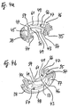
- the control member 35 is provided with two helical ones inner grooves 43, 44 and two flat end surfaces 45, 46 provided which are oriented perpendicular to the axis of rotation 8 of the control member 35, between which the two grooves 43, 44 extend and which each limited by a side flank 47 or 48 extending in a certain manner are.
- first end face 45 of the control member 35 leading first groove 43 goes to the first at a first end 50 (FIG. 4a) End surface 45 and at a second end 51 (Fig. 5b) on that of the steering shaft 3 closer, second end surface 46 of the control member 35 over.
- the vertical side flank 47 of the first end face 45 of the control member 35 runs from the bottom 54 of the first groove 43 of the control member 35 outside in one certain distance 55 past the second groove 44 of the control member 35 the receiving the actuator 10 serving bore 49 of Control member 35 out to end 56 in the bore 49th to be transferred (Fig. 4a, 5a).
- the vertical side flank 48 of the second end surface 46 of the control member 35 extends from the bottom 54 of the first Groove 43 outside at a certain distance 57 past the second groove 44 Bore 49 out to merge into the bore 49 at the relevant end 58 (Fig. 4b, 5b).
- the described steering lock for motor vehicles works as follows.
- the locking member 4 If the locking member 4 is in the locking position, then lies the actuator 10 on a housing-fixed stop 63, namely with of its end face 64 surrounding the locking member 4 on the stop 63 forming bottom of the bore 13 of the housing 2, in which the Actuator 10 is arranged, the cross pin 41 of the Actuator 10 or the two ends 65, 66 of the cross pin 41, which protrude from the transverse bore 42 of the actuator 10 themselves extends immediately adjacent to the second end surface 46 of the control member 35 or extend, namely outside the path along which the End face 62 of the mouth 60 associated with the second end face 46 first groove 43 of the control member 35 moves when the control member 35 is rotated becomes.
- the electric motor 34 is turned on so that it Drive worm 40 in the direction of arrow 68 and the control member 35 in Direction of arrow 69 in Fig. 1 rotates.
- the two ends 65 projecting from the transverse bore 42 of the actuator 10, 66 of the cross pin 41 of the actuator 10, the second end surface 46 of the Leave control member 35 and in both of them helical running grooves 43, 44 enter to in the grooves 43, 44 of the second Ends 51, 53 to run to their first ends 50, 52.
- the two go out of the transverse bore 42 of the Actuator 10 projecting ends 65, 66 from its cross pin 41 on the first end surface 45 of the control member 35 over to on the first end surface 45 away from the first ends 50, 52 of the grooves 43, 44 of the control member 35 to run.
- the upper transverse pin end 66 in FIG. 1 comes on the side flank 47 of the first end face 45 to the plant, and that at the point 70 to the further rotation of the control member 35 in the direction of arrow 69 by the Section of the side flank 47, which is between the point 70 and the End 56 of the side flank 47 extends into the transverse bore 42 of the Actuator 10 to be pushed in, so that the lower in Fig.
- control member 35 can then still in any Direction of arrow 74 can be rotated without any movement of the Actuate actuator 10 and the locking member 4 because the Side flank 48 of the second end surface 46 analogous to the side flank 47 of the first end surface 45 of the control member 35 and an analog Axial displacement of the cross pin 41 of the actuator 10 in its Cross bore 42 causes.
- the electric motor 34 does not have to stop immediately when the locking member 4 the unlocked position or the locked position and that Actuator 10 has reached the corresponding axial position. Rather, it can then definitely in the direction of arrow 68 or in the direction of arrow 73 and the control member 35 through any angle continue to turn in the direction of arrow 69 or in the direction of arrow 74 without that the locking member 4 and the actuator 10 move and that Locking element 4 the unlocking position or the locking position and that Actuator 10 would leave the corresponding axial position.
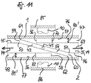
- 9 to 11 are various options for both the training of two mouths 59, 60 of the first groove 43 and the two end faces 45, 46 the control member 35 and the support of the actuator 10 in Housing 2 schematically illustrated.
- the first groove 43 of the control member 35 extends on the one hand up to that lying on the annular surface 37 of the cover 1 of the housing 2 first end face 76 of the control member 35 and on the other hand up to that at the Annular surface 36 of the housing 2 adjacent second end surface 77 of the Control member 35 so that the first end face 45 of the control member 35th associated mouth 59 of the first groove 43 on the first end face 45 distal and opposite side of the first end 50 of the first groove 43 from a sharp, linear edge 78 and that of the second end surface 46 of the control member 35 associated mouth 60 of the first groove 43 on the distal second end surface 46 and the second end 51 of the first groove 43 opposite side also from a sharp, linear edge 79 is limited.
- the first end surface 45 is at a distance 80 from the first End face 76 of the control member 35 is arranged, which is the diameter the cross pin 41 of the actuator 10 is adapted.
- the distance too 81 of the second end surface 46 of the second end surface 77 of the control member 35 corresponds essentially to the diameter of the cross pin 41 of the Actuator 10.
- the actuator 10 is only by means of Cross pin 41 supported against the housing 2.
- the variants according to FIGS. 10, 11 differ only in that 9 that the two mouths 59, 60 of the first groove 43 of the Control member 35 each have the described end face 61 and 62 and the actuator 10 via a compression spring 83 on the cover 1 of the housing 2 and a compression spring 84 is supported on the housing 2 or with a stop 85 cooperates on the cover 1 and a stop 86 on the housing 2.
- the Compression springs 83, 84 each press the cross pin 41 of the actuator 10 against the first end face 45 of the control member 35 and from the end face 61 the associated mouth 59 away or against the second end surface 46 of the Control member 35 and from the end face 62 of the associated mouth 60th path.
- the stops 85, 86 hold the cross pin 41 of the actuator 10 in each case on the first end face 45 and from the end face 61 of the associated one Mouth 59 removed or on the second end surface 46 and from the end face 62 of the associated mouth 60 removed.
- 10 are in the variant of FIG the end faces 61, 62 of the mouths 59, 60 opposite the ends 50, 51 the first groove 43 correspondingly far to the ends 56, 58 of the side flanks 47, 48 of the end faces 45, 46 of the control member 35 are offset.
- the end faces 76, 77 of the Control member 35 each at a correspondingly greater distance 80 'or 81' from the first end surface 45 or from the second end surface 46 of the Control element 35.
Landscapes
- Engineering & Computer Science (AREA)
- Mechanical Engineering (AREA)
- Lock And Its Accessories (AREA)
- Transmission Devices (AREA)
- Gear Transmission (AREA)
Abstract
Description
Claims (6)
- Schloß, insbesondere zum Verriegeln der Lenkspindel (3) oder der Zahnstange des Lenkgetriebes oder der Ausgangswelle des Antriebsgetriebes eines Kraftfahrzeugs, mit einem Sperrglied (4), welches zwischen einer Verriegelungsstellung und einer Entriegelungsstellung hin- und herbewegbar ist, und mit einem mittels eines Antriebs (34) hin- und herdrehbaren Steuerglied (35) zur Axialverschiebung eines mit dem Sperrglied zusammenwirkenden Betätigungsgliedes (10) oder des Sperrgliedes selbst in der einen oder in der anderen Richtung, dadurch gekennzeichnet, daß das Betätigungsglied (10) oder das Sperrglied und das Steuerglied (35) koaxial angeordnet sind und überderart zusammenwirken, daß das Betätigungsglied (10) oder das Sperrglied beim Drehen des Steuergliedes (35) in derjenigen Richtung (69) , in welcher die beiden aus der Querbohrung (42) des Betätigungsgliedes (10) oder des Sperrgliedes vorstehenden Enden (65,66) des Querstiftes (41) in den Nuten (43,44) zu der Endfläche (45) des Steuergliedes (35) hinlaufen, entsprechend axial verschoben wird, um dann, wenn die Enden (65,66) des Querstiftes (41) von den Nuten (43,44) auf die Endfläche (45) übergehen, stillzustehen und in der erreichten Axialstellung zu bleiben, bis das Steuerglied (35) in der entgegengesetzten Richtung (74) gedreht wird und die Enden (65,66) des Querstiftes (41) in den Nuten (43,44) von der Endfläche (45) weg laufen, so daß das Betätigungsglied (10) oder das Sperrglied sich in der entgegengesetzten Richtung axial verschiebt.a) einen Querstift (41), welcher in einer Querbohrung (42) des inneren Betätigungsgliedes (10) oder des inneren Sperrgliedes axial verschieblich ist, undb) zwei schraubenlinienförmig verlaufende innere Nuten (43,44) sowie eine ebene Endfläche (45) des äußeren Steuergliedes (35), welche sich senkrecht zur Drehachse (8) des Steuergliedes (35) erstreckt, an die beiden Nuten (43,44) anschließt und durch eine Seitenflanke (47) begrenzt ist, die vom Boden (54) einer Nut (43) außen im Abstand (55) an der anderen Nut (44) vorbei zum Betätigungsglied (10) oder Sperrglied hin verläuft,
- Schloß nach Anspruch 1, dadurch gekennzeichnet, daß die Mündung (59) derjenigen Nut (43) auf der Endfläche (45) des Steuergliedes (35), an deren Boden (54) die Seitenflanke (47) der Endfläche (45) anschließt, auf der der Endfläche (45) fernen Seite eine Stirnfläche (61) aufweist, welche sich in einer die Drehachse (8) des Steuergliedes (35) enthaltenden Ebene erstreckt, und daß das Betätigungsglied (10) oder das Sperrglied federbelastet ist, um den Querstift (41) gegen die Endfläche (45) und von der Stirnfläche (61) weg zu drücken, oder mit einem Anschlag (85) zusammenwirkt, um den Querstift (41) an der Endfläche (45) und von der Stirnfläche (61) entfernt zu halten.
- Schloß nach Anspruch 1 oder 2, dadurch gekennzeichnet, daß die Nuten (43,44) an den von der ersten Endfläche (45) entfernten Enden (51,53) in eine zweite ebene Endfläche (46) des Steuergliedes (35) übergehen, welche sich senkrecht zur Drehachse (8) des Steuergliedes (35) erstreckt und durch eine Seitenflanke (48) begrenzt ist, die vom Boden (54) einer Nut (43) außen im Abstand (57) an der anderen Nut (44) vorbei zum Betätigungsglied (10) oder Sperrglied hin verläuft, so daß das Betätigungsglied (10) oder das Sperrglied beim Drehen des Steuergliedes (35) in derjenigen Richtung (74) , in welcher die beiden aus der Querbohrung (42) des Betätigungsgliedes (10) oder des Sperrgliedes vorstehenden Enden (65,66) des Querstiftes (41) in den Nuten (43,44) von der ersten Endfläche (45) zu der zweiten Endfläche (46) des Steuergliedes (35) laufen, nach der entsprechenden Axialverschiebung des Betätigungsgliedes (10) oder des Sperrgliedes dann, wenn die Enden (65,66) des Querstiftes (41) von den Nuten (43,44) auf die zweite Endfläche (46) übergehen, stillsteht und in der erreichten Axialstellung bleibt, bis das Steuerglied (35) in der entgegengesetzten Richtung (69) gedreht wird und die Enden (65,66) des Querstiftes (41) in den Nuten (43,44) von der zweiten Endfläche (46) zu der ersten Endfläche (45) laufen, so daß das Betätigungsglied (10) oder das Sperrglied sich in der entgegengesetzten Richtung axial verschiebt.
- Schloß nach Anspruch 3, dadurch gekennzeichnet, daß die Mündung (60) derjenigen Nut (43) auf der zweiten Endfläche (46) des Steuergliedes (35), an deren Boden (54) die Seitenflanke (48) der zweiten Endfläche (46) anschließt, auf der der zweiten Endfläche (46) fernen Seite eine Stirnfläche (62) aufweist, welche sich in einer die Drehachse (8) des Steuergliedes (35) enthaltenden Ebene erstreckt, und daß das Betätigungsglied (10) oder das Sperrglied federbelastet ist, um den Querstift (41) gegen die zweite Endfläche (46) und von der Stirnfläche (62) weg zu drücken, oder mit einem Anschlag (63,86) zusammenwirkt, um den Querstift (41) an der zweiten Endfläche (46) und von der Stirnfläche (62) entfernt zu halten.
- Schloß nach einem der vorstehenden Ansprüche, dadurch gekennzeichnet, daß das Steuerglied (35) eine Außenverzahnung (35) für den Eingriff eines Antriebsritzels oder einer Antriebsschnecke (40) aufweist.
- Schloß nach einem der vorstehenden Ansprüche, dadurch gekennzeichnet, daß ein Elektromotor (34) mit umkehrbarer Drehrichtung als Antrieb für das Steuerglied (35) vorgesehen ist.
Applications Claiming Priority (2)
| Application Number | Priority Date | Filing Date | Title |
|---|---|---|---|
| DE10030688A DE10030688C1 (de) | 2000-06-23 | 2000-06-23 | Schloß, insbesondere zum Verriegeln der Lenkspindel oder der Zahnstange des Lenkgetriebes oder der Ausgangswelle des Antriebsgetriebes eines Kraftfahrzeugs |
| DE10030688 | 2000-06-23 |
Publications (3)
| Publication Number | Publication Date |
|---|---|
| EP1167134A2 true EP1167134A2 (de) | 2002-01-02 |
| EP1167134A3 EP1167134A3 (de) | 2003-12-17 |
| EP1167134B1 EP1167134B1 (de) | 2004-09-29 |
Family
ID=7646591
Family Applications (1)
| Application Number | Title | Priority Date | Filing Date |
|---|---|---|---|
| EP01109431A Expired - Lifetime EP1167134B1 (de) | 2000-06-23 | 2001-04-23 | Schloss, insbesondere zum Verriegeln der Lenkspindel oder der Zahnstange des Lenkgetriebes oder der Ausgangswelle des Antriebsgetriebes eines Kraftfahrzeugs |
Country Status (5)
| Country | Link |
|---|---|
| US (1) | US6543262B2 (de) |
| EP (1) | EP1167134B1 (de) |
| AT (1) | ATE277796T1 (de) |
| DE (2) | DE10030688C1 (de) |
| ES (1) | ES2228689T3 (de) |
Cited By (3)
| Publication number | Priority date | Publication date | Assignee | Title |
|---|---|---|---|---|
| US7260963B2 (en) | 2002-03-22 | 2007-08-28 | Kabushiki Kaisha Tokai Rika Denki Seisakusho | Electric steering lock device |
| DE102008016820A1 (de) * | 2008-04-01 | 2009-10-08 | Huf Hülsbeck & Fürst Gmbh & Co. Kg | Vorrichtung zur Ansteuerung einer Sperreinheit |
| CN103507754A (zh) * | 2012-06-29 | 2014-01-15 | 新昌县冠阳技术开发有限公司 | 一种远程控制自锁的新型汽车防盗装置 |
Families Citing this family (41)
| Publication number | Priority date | Publication date | Assignee | Title |
|---|---|---|---|---|
| DE10103182B4 (de) * | 2001-01-24 | 2012-09-27 | Valeo Sicherheitssysteme Gmbh | Verriegelungsvorrichtung |
| DE10109609C1 (de) * | 2001-02-28 | 2002-10-10 | Huf Huelsbeck & Fuerst Gmbh | Schloß, insbesondere zum Verriegeln der Lenkspindel eines Kraftfahrzeugs |
| DE10118545C1 (de) | 2001-04-14 | 2002-10-10 | Huf Huelsbeck & Fuerst Gmbh | Vorrichtung zur Verriegelung einer Lenksäule in einem Fahrzeug |
| DE10121714C1 (de) * | 2001-05-04 | 2003-01-02 | Huf Huelsbeck & Fuerst Gmbh | Schloß, insbesondere zum Verriegeln der Lenkspindel eines Kraftfahrzeugs |
| JP3808789B2 (ja) * | 2002-03-22 | 2006-08-16 | 株式会社東海理化電機製作所 | 電動ステアリングロック装置 |
| JP2004122996A (ja) * | 2002-10-04 | 2004-04-22 | Yuhshin Co Ltd | 電動ステアリングロック装置 |
| DE10247803B3 (de) * | 2002-10-14 | 2004-01-29 | Huf Hülsbeck & Fürst Gmbh & Co. Kg | Vorrichtung zum Sperren der Lenkspindel eines Kraftfahrzeugs |
| DE10247802B3 (de) * | 2002-10-14 | 2004-02-05 | Huf Hülsbeck & Fürst Gmbh & Co. Kg | Vorrichtung zum Sperren der Lenkspindel eines Kraftfahrzeugs |
| JP2004182177A (ja) * | 2002-12-05 | 2004-07-02 | Yuhshin Co Ltd | 電動ステアリングロック装置 |
| JP2004231123A (ja) * | 2003-01-31 | 2004-08-19 | Tokai Rika Co Ltd | 電動ステアリングロック装置 |
| JP4491416B2 (ja) * | 2003-04-22 | 2010-06-30 | 日本精工株式会社 | ステアリングロック装置 |
| CN100368238C (zh) * | 2003-04-22 | 2008-02-13 | 日本精工株式会社 | 转向锁定装置 |
| DE102004001511B4 (de) * | 2004-01-09 | 2015-02-19 | Continental Automotive Gmbh | Vorrichtung zum Arretieren einer Lenksäule eines Kraftfahrzeuges |
| JP2005297645A (ja) * | 2004-04-07 | 2005-10-27 | Tokai Rika Co Ltd | ステアリングロック装置 |
| US7065993B2 (en) * | 2004-06-04 | 2006-06-27 | U-Shin Ltd. | Motor-driven steering lock device |
| DE102004043898B3 (de) * | 2004-09-10 | 2005-12-01 | Huf Hülsbeck & Fürst Gmbh & Co. Kg | Vorrichtung zum Sperren der Lenkspindel eines Kraftfahrzeugs |
| ATE527141T1 (de) | 2005-03-02 | 2011-10-15 | Huf Huelsbeck & Fuerst Gmbh | Verriegelungsvorrichtung für eine lenkspindel und anwendungsspezifische integrierte schaltung hierfür |
| DE102005021050B3 (de) * | 2005-05-06 | 2006-11-30 | Huf Hülsbeck & Fürst Gmbh & Co. Kg | Vorrichtung zum Sperren der Lenkspindel eines Kraftfahrzeugs |
| JP4694384B2 (ja) * | 2006-02-17 | 2011-06-08 | 株式会社東海理化電機製作所 | ステアリングロック装置 |
| DE102006042511B4 (de) | 2006-09-07 | 2019-05-16 | Huf Hülsbeck & Fürst Gmbh & Co. Kg | Kompakte Verriegelungsvorrichtung |
| US7762110B2 (en) * | 2006-10-06 | 2010-07-27 | U-Shin, Ltd. | Steering lock unit |
| US7870768B2 (en) * | 2006-10-27 | 2011-01-18 | U-Shin Ltd. | Power steering lock unit |
| US7787260B2 (en) * | 2007-07-09 | 2010-08-31 | Adc Telecommunications, Inc. | Cable management arrangement for a telecommunications cabinet |
| US7596976B2 (en) * | 2007-11-30 | 2009-10-06 | Alpha Corporation | Electric steering lock device |
| DE102007059713A1 (de) * | 2007-12-10 | 2009-06-18 | Huf Hülsbeck & Fürst Gmbh & Co. Kg | Vorrichtung zur Ansteuerung eines Sperrgliedes |
| DE102007059712A1 (de) * | 2007-12-10 | 2009-06-25 | Huf Hülsbeck & Fürst Gmbh & Co. Kg | Vorrichtung zur Ansteuerung eines Sperrgliedes |
| DE102008040877A1 (de) * | 2008-07-31 | 2010-02-04 | Zf Lenksysteme Gmbh | Vorrichtung zum Verriegeln einer Lenkung und damit ausgestattetes Lenksystem |
| JP5465851B2 (ja) * | 2008-08-05 | 2014-04-09 | 株式会社アルファ | ステアリングロック装置 |
| JP5385724B2 (ja) * | 2008-08-29 | 2014-01-08 | 株式会社アルファ | ステアリングロック装置 |
| CN101824941B (zh) * | 2009-03-06 | 2014-07-09 | 株式会社有信 | 电动转向锁定装置 |
| DE102009045905A1 (de) * | 2009-10-21 | 2011-04-28 | Huf Hülsbeck & Fürst Gmbh & Co. Kg | Vorrichtung zur Verlagerung einer verschiebbaren Sperreinheit |
| FR2952006B1 (fr) * | 2009-11-05 | 2012-01-06 | Valeo Securite Habitacle | Dispositif antivol pour colonne de direction de vehicule muni d'un actionnneur de pene a course morte |
| US8424348B2 (en) * | 2010-01-27 | 2013-04-23 | Strattec Security Corporation | Steering lock |
| US20140069224A1 (en) | 2012-09-07 | 2014-03-13 | Strattec Security Corporation | Steering lock |
| JP5520683B2 (ja) * | 2010-05-11 | 2014-06-11 | 株式会社東海理化電機製作所 | イグニッションスイッチの操作規制機構 |
| JP5394981B2 (ja) * | 2010-05-13 | 2014-01-22 | 株式会社東海理化電機製作所 | イグニッションスイッチの操作規制装置 |
| JP6325207B2 (ja) * | 2013-07-01 | 2018-05-16 | 株式会社ユーシン | 電動ステアリングロック装置 |
| JP6122358B2 (ja) * | 2013-07-01 | 2017-04-26 | 株式会社ユーシン | 電動ステアリングロック装置 |
| US9221427B2 (en) * | 2014-02-11 | 2015-12-29 | Steering Solutions Ip Holding Corporation | System for selectively locking a steering column |
| US9731681B2 (en) * | 2014-04-29 | 2017-08-15 | Strattec Security Corporation | Steering lock |
| US11584426B2 (en) * | 2019-04-24 | 2023-02-21 | Steering Solutions Ip Holding Corporation | Rotational centering device for steering column |
Citations (1)
| Publication number | Priority date | Publication date | Assignee | Title |
|---|---|---|---|---|
| DE4436326C1 (de) | 1994-10-11 | 1995-10-19 | Huelsbeck & Fuerst | Schloß, insbesondere zum Verriegeln der Lenkspindel oder der Zahnstange des Lenkgetriebes oder der Ausgangswelle des Antriebsgetriebes eines Kraftfahrzeugs |
Family Cites Families (11)
| Publication number | Priority date | Publication date | Assignee | Title |
|---|---|---|---|---|
| US1736900A (en) * | 1928-01-07 | 1929-11-26 | Arthur H Hough | Steering-wheel lock for automobiles |
| WO1983004228A1 (fr) * | 1982-05-27 | 1983-12-08 | Neiman S.A. | Serrure cylindrique, notamment verrou de direction pour vehicule automobile |
| JPH06158924A (ja) * | 1992-11-25 | 1994-06-07 | Tokai Rika Co Ltd | ステアリングロック装置 |
| JP3095328B2 (ja) * | 1994-10-06 | 2000-10-03 | 株式会社東海理化電機製作所 | ステアリングロック装置 |
| DE29611043U1 (de) * | 1996-06-24 | 1996-08-29 | Hülsbeck & Fürst GmbH & Co KG, 42551 Velbert | Lenkschloß für Kraftfahrzeuge |
| US5718132A (en) * | 1996-08-05 | 1998-02-17 | General Motors Corporation | Anti-theft steering shaft lock |
| US5974841A (en) * | 1997-03-28 | 1999-11-02 | Honda Lock Mfg. Co., Ltd. | Steering lock device |
| DE19727422C1 (de) * | 1997-06-27 | 1998-06-25 | Meyers Pierre | Koppelsystem für elektronische Verschlußeinrichtungen |
| US5906120A (en) * | 1998-04-09 | 1999-05-25 | Ford Global Technologies, Inc. | Automotive vehicle steering column lock mechanism |
| DE19929435C2 (de) * | 1999-06-26 | 2002-05-23 | Huf Huelsbeck & Fuerst Gmbh | Vorrichtung zur Positionserkennung eines beweglichen Glieds in einem bei Fahrzeugen anwendbaren Verschluss |
| DE29919649U1 (de) * | 1999-11-09 | 2000-03-30 | Hartmann, Jörg, Dipl.-Math., 18106 Rostock | Einrichtung zur Sicherung von Fahrzeugen durch gezielte Unterbrechung der Lenkung |
-
2000
- 2000-06-23 DE DE10030688A patent/DE10030688C1/de not_active Expired - Fee Related
-
2001
- 2001-04-23 EP EP01109431A patent/EP1167134B1/de not_active Expired - Lifetime
- 2001-04-23 AT AT01109431T patent/ATE277796T1/de not_active IP Right Cessation
- 2001-04-23 ES ES01109431T patent/ES2228689T3/es not_active Expired - Lifetime
- 2001-04-23 DE DE50103830T patent/DE50103830D1/de not_active Expired - Lifetime
- 2001-06-21 US US09/885,122 patent/US6543262B2/en not_active Expired - Fee Related
Patent Citations (1)
| Publication number | Priority date | Publication date | Assignee | Title |
|---|---|---|---|---|
| DE4436326C1 (de) | 1994-10-11 | 1995-10-19 | Huelsbeck & Fuerst | Schloß, insbesondere zum Verriegeln der Lenkspindel oder der Zahnstange des Lenkgetriebes oder der Ausgangswelle des Antriebsgetriebes eines Kraftfahrzeugs |
Cited By (3)
| Publication number | Priority date | Publication date | Assignee | Title |
|---|---|---|---|---|
| US7260963B2 (en) | 2002-03-22 | 2007-08-28 | Kabushiki Kaisha Tokai Rika Denki Seisakusho | Electric steering lock device |
| DE102008016820A1 (de) * | 2008-04-01 | 2009-10-08 | Huf Hülsbeck & Fürst Gmbh & Co. Kg | Vorrichtung zur Ansteuerung einer Sperreinheit |
| CN103507754A (zh) * | 2012-06-29 | 2014-01-15 | 新昌县冠阳技术开发有限公司 | 一种远程控制自锁的新型汽车防盗装置 |
Also Published As
| Publication number | Publication date |
|---|---|
| EP1167134B1 (de) | 2004-09-29 |
| DE50103830D1 (de) | 2004-11-04 |
| US6543262B2 (en) | 2003-04-08 |
| DE10030688C1 (de) | 2001-10-18 |
| ATE277796T1 (de) | 2004-10-15 |
| EP1167134A3 (de) | 2003-12-17 |
| US20020029595A1 (en) | 2002-03-14 |
| ES2228689T3 (es) | 2005-04-16 |
Similar Documents
| Publication | Publication Date | Title |
|---|---|---|
| EP1167134B1 (de) | Schloss, insbesondere zum Verriegeln der Lenkspindel oder der Zahnstange des Lenkgetriebes oder der Ausgangswelle des Antriebsgetriebes eines Kraftfahrzeugs | |
| EP1363815B1 (de) | Schloss, insbesondere zum verriegeln der lenkspindel eines kraftfahrzeugs | |
| EP1236626B1 (de) | Schloss, insbesondere zum Verriegeln der Lenkspindel eines Kraftfahrzeugs | |
| EP1110828B1 (de) | Verriegelungsvorrichtung | |
| EP1558474B1 (de) | Vorrichtung zum sperren der lenkspindel eines kraftfahrzeugs | |
| DE10247802B3 (de) | Vorrichtung zum Sperren der Lenkspindel eines Kraftfahrzeugs | |
| EP1725437B1 (de) | Vorrichtung zum sperren der lenkspindel eines kraftfahrzeugs | |
| DE3616122C2 (de) | Lenk- und Zündschloß | |
| DE9116447U1 (de) | Elektromotorischer Antrieb für eine Zentralverriegelungsvorrichtung an einem Kraftfahrzeug | |
| DE4436326C1 (de) | Schloß, insbesondere zum Verriegeln der Lenkspindel oder der Zahnstange des Lenkgetriebes oder der Ausgangswelle des Antriebsgetriebes eines Kraftfahrzeugs | |
| DE102007059710B4 (de) | Kompakte Verriegelungsvorrichtung mit Sicherungselement | |
| DE3439705C2 (de) | ||
| DE102019128563A1 (de) | Elektromechanischer Parksperrenaktuator | |
| DE69606126T2 (de) | Angetriebenes Lenkradschloss für Kraftfahrzeuge | |
| DE4407912C2 (de) | Elektromechanisches Schloß | |
| EP1249375B1 (de) | Vorrichtung zur Verriegelung einer Lenksäule in einem Fahrzeug | |
| DE4039652C1 (en) | Detachable safety-interlock for electrical switch - has key guides chamfered to facilitate final engagement with coded cam | |
| DE2925808A1 (de) | Diebstahlsicherung | |
| DE19526660B4 (de) | Elektromechanisches Schloß | |
| DE19809346B4 (de) | Elektromechanische Schließvorrichtung, insbesondere Schloß | |
| DE69705377T2 (de) | Antrieb, insbesondere für eine elektrische Fahrzeugdiebstahlsicherung | |
| EP0943762A2 (de) | Mechanisch und elektrisch codierte Verriegelungs- und Entriegelungsvorrichtung | |
| EP1226372A1 (de) | Möbelantrieb | |
| DE2314585C3 (de) | Scheibenwischerantrieb | |
| DE3224411C1 (de) | Kraftfahrzeug-Lenkschloss |
Legal Events
| Date | Code | Title | Description |
|---|---|---|---|
| PUAI | Public reference made under article 153(3) epc to a published international application that has entered the european phase |
Free format text: ORIGINAL CODE: 0009012 |
|
| AK | Designated contracting states |
Kind code of ref document: A2 Designated state(s): AT BE CH CY DE DK ES FI FR GB GR IE IT LI LU MC NL PT SE TR |
|
| AX | Request for extension of the european patent |
Free format text: AL;LT;LV;MK;RO;SI |
|
| PUAL | Search report despatched |
Free format text: ORIGINAL CODE: 0009013 |
|
| AK | Designated contracting states |
Kind code of ref document: A3 Designated state(s): AT BE CH CY DE DK ES FI FR GB GR IE IT LI LU MC NL PT SE TR |
|
| AX | Request for extension of the european patent |
Extension state: AL LT LV MK RO SI |
|
| 17P | Request for examination filed |
Effective date: 20031210 |
|
| GRAP | Despatch of communication of intention to grant a patent |
Free format text: ORIGINAL CODE: EPIDOSNIGR1 |
|
| GRAS | Grant fee paid |
Free format text: ORIGINAL CODE: EPIDOSNIGR3 |
|
| GRAA | (expected) grant |
Free format text: ORIGINAL CODE: 0009210 |
|
| AKX | Designation fees paid |
Designated state(s): AT BE CH CY DE DK ES FI FR GB GR IE IT LI LU MC NL PT SE TR |
|
| AK | Designated contracting states |
Kind code of ref document: B1 Designated state(s): AT BE CH CY DE DK ES FI FR GB GR IE IT LI LU MC NL PT SE TR |
|
| PG25 | Lapsed in a contracting state [announced via postgrant information from national office to epo] |
Ref country code: IE Free format text: LAPSE BECAUSE OF FAILURE TO SUBMIT A TRANSLATION OF THE DESCRIPTION OR TO PAY THE FEE WITHIN THE PRESCRIBED TIME-LIMIT Effective date: 20040929 Ref country code: FI Free format text: LAPSE BECAUSE OF FAILURE TO SUBMIT A TRANSLATION OF THE DESCRIPTION OR TO PAY THE FEE WITHIN THE PRESCRIBED TIME-LIMIT Effective date: 20040929 Ref country code: NL Free format text: LAPSE BECAUSE OF FAILURE TO SUBMIT A TRANSLATION OF THE DESCRIPTION OR TO PAY THE FEE WITHIN THE PRESCRIBED TIME-LIMIT Effective date: 20040929 Ref country code: TR Free format text: LAPSE BECAUSE OF FAILURE TO SUBMIT A TRANSLATION OF THE DESCRIPTION OR TO PAY THE FEE WITHIN THE PRESCRIBED TIME-LIMIT Effective date: 20040929 |
|
| REG | Reference to a national code |
Ref country code: GB Ref legal event code: FG4D Free format text: NOT ENGLISH |
|
| REG | Reference to a national code |
Ref country code: CH Ref legal event code: EP |
|
| GBT | Gb: translation of ep patent filed (gb section 77(6)(a)/1977) | ||
| REG | Reference to a national code |
Ref country code: IE Ref legal event code: FG4D Free format text: GERMAN |
|
| REF | Corresponds to: |
Ref document number: 50103830 Country of ref document: DE Date of ref document: 20041104 Kind code of ref document: P |
|
| PG25 | Lapsed in a contracting state [announced via postgrant information from national office to epo] |
Ref country code: SE Free format text: LAPSE BECAUSE OF FAILURE TO SUBMIT A TRANSLATION OF THE DESCRIPTION OR TO PAY THE FEE WITHIN THE PRESCRIBED TIME-LIMIT Effective date: 20041229 Ref country code: GR Free format text: LAPSE BECAUSE OF FAILURE TO SUBMIT A TRANSLATION OF THE DESCRIPTION OR TO PAY THE FEE WITHIN THE PRESCRIBED TIME-LIMIT Effective date: 20041229 Ref country code: DK Free format text: LAPSE BECAUSE OF FAILURE TO SUBMIT A TRANSLATION OF THE DESCRIPTION OR TO PAY THE FEE WITHIN THE PRESCRIBED TIME-LIMIT Effective date: 20041229 |
|
| NLV1 | Nl: lapsed or annulled due to failure to fulfill the requirements of art. 29p and 29m of the patents act | ||
| REG | Reference to a national code |
Ref country code: ES Ref legal event code: FG2A Ref document number: 2228689 Country of ref document: ES Kind code of ref document: T3 |
|
| REG | Reference to a national code |
Ref country code: IE Ref legal event code: FD4D |
|
| PG25 | Lapsed in a contracting state [announced via postgrant information from national office to epo] |
Ref country code: CY Free format text: LAPSE BECAUSE OF FAILURE TO SUBMIT A TRANSLATION OF THE DESCRIPTION OR TO PAY THE FEE WITHIN THE PRESCRIBED TIME-LIMIT Effective date: 20050423 Ref country code: AT Free format text: LAPSE BECAUSE OF NON-PAYMENT OF DUE FEES Effective date: 20050423 Ref country code: LU Free format text: LAPSE BECAUSE OF NON-PAYMENT OF DUE FEES Effective date: 20050423 |
|
| PG25 | Lapsed in a contracting state [announced via postgrant information from national office to epo] |
Ref country code: LI Free format text: LAPSE BECAUSE OF NON-PAYMENT OF DUE FEES Effective date: 20050430 Ref country code: CH Free format text: LAPSE BECAUSE OF NON-PAYMENT OF DUE FEES Effective date: 20050430 Ref country code: BE Free format text: LAPSE BECAUSE OF NON-PAYMENT OF DUE FEES Effective date: 20050430 Ref country code: MC Free format text: LAPSE BECAUSE OF NON-PAYMENT OF DUE FEES Effective date: 20050430 |
|
| ET | Fr: translation filed | ||
| PLBE | No opposition filed within time limit |
Free format text: ORIGINAL CODE: 0009261 |
|
| STAA | Information on the status of an ep patent application or granted ep patent |
Free format text: STATUS: NO OPPOSITION FILED WITHIN TIME LIMIT |
|
| 26N | No opposition filed |
Effective date: 20050630 |
|
| BERE | Be: lapsed |
Owner name: HULSBECK & FURST G.M.B.H. & CO. K.G. *HUF Effective date: 20050430 |
|
| REG | Reference to a national code |
Ref country code: CH Ref legal event code: PL |
|
| BERE | Be: lapsed |
Owner name: HULSBECK & FURST G.M.B.H. & CO. K.G. *HUF Effective date: 20050430 |
|
| PG25 | Lapsed in a contracting state [announced via postgrant information from national office to epo] |
Ref country code: PT Free format text: LAPSE BECAUSE OF NON-PAYMENT OF DUE FEES Effective date: 20050228 |
|
| PG25 | Lapsed in a contracting state [announced via postgrant information from national office to epo] |
Ref country code: IT Free format text: LAPSE BECAUSE OF NON-PAYMENT OF DUE FEES Effective date: 20080423 |
|
| PGFP | Annual fee paid to national office [announced via postgrant information from national office to epo] |
Ref country code: GB Payment date: 20140429 Year of fee payment: 14 |
|
| PGFP | Annual fee paid to national office [announced via postgrant information from national office to epo] |
Ref country code: IT Payment date: 20140428 Year of fee payment: 14 Ref country code: ES Payment date: 20140430 Year of fee payment: 14 |
|
| GBPC | Gb: european patent ceased through non-payment of renewal fee |
Effective date: 20150423 |
|
| PG25 | Lapsed in a contracting state [announced via postgrant information from national office to epo] |
Ref country code: IT Free format text: LAPSE BECAUSE OF NON-PAYMENT OF DUE FEES Effective date: 20150423 Ref country code: GB Free format text: LAPSE BECAUSE OF NON-PAYMENT OF DUE FEES Effective date: 20150423 |
|
| REG | Reference to a national code |
Ref country code: FR Ref legal event code: PLFP Year of fee payment: 16 |
|
| REG | Reference to a national code |
Ref country code: ES Ref legal event code: FD2A Effective date: 20160527 |
|
| PG25 | Lapsed in a contracting state [announced via postgrant information from national office to epo] |
Ref country code: ES Free format text: LAPSE BECAUSE OF NON-PAYMENT OF DUE FEES Effective date: 20150424 |
|
| REG | Reference to a national code |
Ref country code: FR Ref legal event code: PLFP Year of fee payment: 17 |
|
| REG | Reference to a national code |
Ref country code: FR Ref legal event code: PLFP Year of fee payment: 18 |
|
| PGFP | Annual fee paid to national office [announced via postgrant information from national office to epo] |
Ref country code: FR Payment date: 20180424 Year of fee payment: 18 |
|
| PGFP | Annual fee paid to national office [announced via postgrant information from national office to epo] |
Ref country code: DE Payment date: 20190418 Year of fee payment: 19 |
|
| REG | Reference to a national code |
Ref country code: DE Ref legal event code: R084 Ref document number: 50103830 Country of ref document: DE |
|
| PG25 | Lapsed in a contracting state [announced via postgrant information from national office to epo] |
Ref country code: FR Free format text: LAPSE BECAUSE OF NON-PAYMENT OF DUE FEES Effective date: 20190430 |
|
| REG | Reference to a national code |
Ref country code: DE Ref legal event code: R119 Ref document number: 50103830 Country of ref document: DE |
|
| PG25 | Lapsed in a contracting state [announced via postgrant information from national office to epo] |
Ref country code: DE Free format text: LAPSE BECAUSE OF NON-PAYMENT OF DUE FEES Effective date: 20201103 |