EP1167222A2 - Behälter mit Randbordierung und Verfahren zur Herstellung der Randbordierung - Google Patents
Behälter mit Randbordierung und Verfahren zur Herstellung der Randbordierung Download PDFInfo
- Publication number
- EP1167222A2 EP1167222A2 EP01115153A EP01115153A EP1167222A2 EP 1167222 A2 EP1167222 A2 EP 1167222A2 EP 01115153 A EP01115153 A EP 01115153A EP 01115153 A EP01115153 A EP 01115153A EP 1167222 A2 EP1167222 A2 EP 1167222A2
- Authority
- EP
- European Patent Office
- Prior art keywords
- container
- section
- container body
- edge
- bordering
- Prior art date
- Legal status (The legal status is an assumption and is not a legal conclusion. Google has not performed a legal analysis and makes no representation as to the accuracy of the status listed.)
- Granted
Links
- 238000000034 method Methods 0.000 title claims abstract description 20
- 238000004519 manufacturing process Methods 0.000 title claims abstract description 5
- 239000002184 metal Substances 0.000 claims abstract description 6
- 238000000465 moulding Methods 0.000 claims description 9
- 238000007789 sealing Methods 0.000 claims description 9
- 238000007493 shaping process Methods 0.000 claims description 2
- 238000007688 edging Methods 0.000 description 4
- 238000005096 rolling process Methods 0.000 description 4
- 238000007906 compression Methods 0.000 description 2
- 238000006073 displacement reaction Methods 0.000 description 2
- 238000013459 approach Methods 0.000 description 1
- 239000011324 bead Substances 0.000 description 1
- 230000015572 biosynthetic process Effects 0.000 description 1
- 150000001875 compounds Chemical class 0.000 description 1
- 230000006835 compression Effects 0.000 description 1
- 230000001419 dependent effect Effects 0.000 description 1
- 230000003014 reinforcing effect Effects 0.000 description 1
- 238000009966 trimming Methods 0.000 description 1
Images




Classifications
-
- B—PERFORMING OPERATIONS; TRANSPORTING
- B65—CONVEYING; PACKING; STORING; HANDLING THIN OR FILAMENTARY MATERIAL
- B65D—CONTAINERS FOR STORAGE OR TRANSPORT OF ARTICLES OR MATERIALS, e.g. BAGS, BARRELS, BOTTLES, BOXES, CANS, CARTONS, CRATES, DRUMS, JARS, TANKS, HOPPERS, FORWARDING CONTAINERS; ACCESSORIES, CLOSURES, OR FITTINGS THEREFOR; PACKAGING ELEMENTS; PACKAGES
- B65D45/00—Clamping or other pressure-applying devices for securing or retaining closure members
- B65D45/32—Clamping or other pressure-applying devices for securing or retaining closure members for applying radial or radial and axial pressure, e.g. contractible bands encircling closure member
Definitions
- the present invention relates to a container made of sheet metal with a rim.
- the invention further relates to a method for producing the edge bordering of a such a container.
- a container which can be closed with a lid is known from EP 0 565 762 A1.
- the opening-side edge of the container made of sheet metal has a border with an edge Wrap angle of at least 360 ° to that provided with a contact section on which the clamping ring of the container is supported.
- the edge trim also points a support section on the one hand on the inside of the border and on the other hand is supported on the inside of the contact section.
- edge trimmings also have a support section, the on the one hand on the inside of the border and on the other hand on the inside of the System section supports.
- the invention is therefore based on the object of creating a container whose Edge trim should not be deformed, even under heavy mechanical loads can, so that there is no risk of leakage.
- the closable container made of sheet metal comprises a container body, a lid and a clamping ring.
- the container body has an opening side Edge with a spiral border.
- the lid is held by means of a clamping ring with the interposition of a sealing element pressed against the rim, so that the container is tightly closed.
- the clamping ring can be of conventional design be a U-shaped cross section, the opening of the U-shaped cross section in points in the radial direction inwards, so that the parts to be clamped enclosed on the edge become.
- the bordering has a contact section for contacting the clamping ring, so that the force can be transferred from the clamping ring to the edge trim.
- the Edge trim also has a support section.
- the support section is supported on the one hand on an inside of the border and runs on the other hand in one right angle towards the inside of the contact section.
- the support section thus has the function of a reinforcing rib.
- the container according to the invention has the advantage that the contact section through the Supporting section is supported so that the force introduced via the contact section is received by the support section.
- the support section runs in the direction of Surface normals of the contact section and thus in the direction of the resulting force.
- the container according to the invention extends the support section to a central area of the inside of the contact section.
- the Contact section formed rectilinear the term rectilinearly referring to it Cross-section relates.
- the straightforward design of the plant section enables one Simply slide the clamping ring on to the side and lay it flat on the plant section. Due to the flat system, the contact pressure is even transferred to the plant section.
- the edge trim preferably has a wrap angle of more than 450 ° on. From a wrap angle of 450 °, the system section is inclined reached against the container wall, so that the clamping ring has the rim can reach under in the area of the plant section.
- the wrap angle is preferably 510 °, so that the angle between the straight contact section and the side tank wall is 120 °.
- the container body is advantageously drawn in in the region of the edge border.
- the container body thus has a smaller diameter in the area of the edge trim than in a lower area so that the outside diameter of the fastened Clamping ring smaller than or as large as the maximum outer diameter of the container body is in the lower area.
- This embodiment has the advantage that the When tipping over, the container does not first hit the base with the clamping ring, thereby avoiding damage.
- the Lid cup-shaped, the edge of the lid with a radially after outside flanging is provided, which has a wrap angle of 180 ° having.
- the semicircular flange can be on the edge flange of the container body rest while the bottom of the cup-shaped lid is in the opening of the container body protrudes.
- the sealing element is preferably inside the flange arranged.
- a sealing element are conventional ring-shaped sealing elements or foamed seals, e.g. PU or PVC seals, to understand which seal the container body along the entire rim.
- the clamping ring can have a contact element, which is preferably located on the container body supports flat, so that only a defined contact pressure when tensioning the clamping ring can be exercised on the border.
- the method according to the invention for producing a container with bordering comprises the process steps of producing a spiral pre-bordering on Edge of the container body and the deformation of the pre-bordering by a radial after inward movement of a mold that has a negative shape for Manufacture of the edging.
- the negative form essentially has a lower one rectilinear shaped section for shaping the contact section of the border.
- the pre-bordering can be produced, for example, by rolling or upsetting processes take place, which can be carried out in several steps.
- the mold surrounds the pre-bordering and is moved radially against it, the Pre-bordering is caused by the movement of the molding tool in its negative form, so that the pre-bordering is deformed at a correspondingly high contact pressure.
- the inventive method has the advantage that to achieve the final shape Bordering only one step is necessary.
- Forming tool moved radially inwards after deforming the pre-bordering, so that the diameter of the container body is reduced in an upper area becomes.
- the diameter of the container in the region of the bordering the same work step in which the final shape of the Bordering is carried out, which increases productivity.
- the diameter of the container body is preferably such in an upper region reduced that the outer diameter of the border is smaller than the maximum Outside diameter of the container body is in a lower area.
- FIG. 1 shows a side view of the container in a first embodiment
- FIG. 2 shows a side view of the container in a second embodiment
- the containers have a container body 2 or 2 ', which is bucket-shaped.
- the container body 2 and 2 ' are closed on the opening side by a cover 4, which is only is shown in dashed lines.
- the lid 4 is cup-shaped and so on the container body 2 or 2 'placed that the lid 4 with its lid bottom 6 in protrudes the container body 2 or 2 '.
- the edge of the cup-shaped lid 4 is with a radially outwardly extending flange 8 which has a wrap angle of 180 °.
- the crimp 8, which is semicircular in cross section, lies on the edge (not shown) of the container body 2 or 2 '.
- the lid 8 will pressed onto the container body 2 or 2 'by means of a circular clamping ring 10.
- the clamping ring 10 encompasses the flange 8 of the cover and the edge (not shown) of the container body 2 or 2 ', wherein the clamping ring 10 can be released to to remove the cover 4.
- the clamping ring 10 has a contact element surrounding the container 12 on, in the tensioned state of the clamping ring 10 on the sides of the container body 2 or 2 'around its entire circumference.
- the container is drawn in in such a way that the outer diameter d 2 of the attached clamping ring 10 is smaller than the diameter d 3 in the lower region b of the beads or, if appropriate, the fold connection of the container body 2.
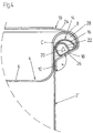
- FIG. 3 and 4 show section A of FIG. 1 and section B of FIG. 2, respectively in a sectional view.
- the container body 2 or 2 ' has an opening side Edge with a spiral border 14 on.
- the border 14 includes a first section 16, a contact section 18, a second section 20 and a support section 22.
- the first section 16 of the border 14 extends radially outwards with a wrap angle of about 180 ° and goes into the contact section 18 over.
- the contact section 18 is rectilinear and extends radially obliquely inwards, being between the contact section 18 and the side of the container body 2 or 2 'an angle ⁇ of approximately 120 ° is formed.
- the investment section passes into the second section 20, which in turn is curved and extends to a region c in which the second section 20 the inside of the first section 16 of the border 14 touches.
- the second goes Section 20 in the support section 22, which extends to a central area of the Extends inside of the contact section 18 of the rim 14, the support section 22 at a substantially right angle on the inside of the contact section 18 approaches.
- the wrap angle of the border 14 is thus a total 510 °.
- the area facing the inside of the contact section 18 Support section 22 is substantially rectilinear.
- the clamping ring 10 has a substantially U-shaped cross section, the first of which Leg 24 overlaps the flange 8 of the cover 4 and its second leg 26 the Rims 14 of the container body 2 or 2 'engages under.
- the inside of the second Leg 26 lies flat against the contact section 18 of the edge flange 14, the pressure applied by the fastening of the clamping ring 10 evenly the contact section 18 is distributed by the arrangement of the support section perpendicular thereto 22 is supported in an ideal manner with respect to area c. So is one ensures high stability of the border 14, which ultimately leads to greater security leads to the tightness of the container.
- contact element 12 lies flat against the side of the container body 2 or 2 ' and thus the side of the container body by tensioning the clamping ring 10 2 or 2 'applied pressure is reduced by a larger contact surface. Indeed it should be noted that a contact element 12 is not in both embodiments is imperative.
- a sealing element 28 is provided, which in the present embodiments is formed by a foamed sealing compound in the flange. At the Bracing the cover 4 with the container body 2 or 2 ′ becomes the sealing element 28 against the outside of the first section 16 of the rim of the container body 2 or 2 'pressed and deforms elastically.
- 5a to 5f show a schematic representation of the method according to the invention for producing the rim of the container according to the invention.
- 5a and 5b illustrate the steps for producing a spiral Pre-bordering on the edge of the container body 2, either using an upsetting process or a rolling process is used.
- a compression tool 30 is used in the compression process.
- the one-piece Upsetting tool 30 has a first cylindrical section 32, the diameter of which corresponds to the inside diameter of the container body 2. Furthermore, the upsetting tool 30 on a second substantially cylindrical portion 34, which is in the feed direction is arranged behind the first cylindrical portion 32 and a larger one Has diameter than the first cylindrical portion 32. Both cylindrical Sections 32, 34 are arranged coaxially. On the container body 2 facing The side of the second cylindrical portion 34 is a semi-circular in cross section Groove 36 is provided, which surrounds the first cylindrical portion 32 in a circle.
- a first step the upsetting tool 30 is countered on the opening side pressed the container body 2, the first cylindrical portion 32 into the interior of the Container body 2 is advanced. The edge of the Container body 2 to the semicircular groove 36 and is pushed forward deformed along the groove 36. The upsetting tool is advanced until the pre-bordering 38 has a wrap angle of 270 °.
- a second upsetting tool 30 ' is used, which is similar to the first Upsetting tool 30 has a first cylindrical section 32 ', a second cylindrical section Section 34 'and a groove 36', wherein the groove 36 'of the second upsetting tool 32 'has a larger radius in cross section than the groove 36.
- the second upsetting tool 30 ' is advanced like the first upsetting tool 30 until the pre-bordering 38 has a wrap angle of 510 °.
- rollers 40, 40 ' for use, which roll on the edge of the container body 2, wherein in The rollers 40, 40 'are provided with circumferential grooves 42, 42' which are semicircular in cross section are.
- a force is exerted on the edge which extends along the grooves 40, 40 'deformed.
- two work steps are carried out (Fig. 5a and Fig. 5b), the roller 40 'used in the second step having a groove 42' which has a larger cross section than the groove 42 in the first roller 40 Has.
- 5c to 5f illustrate the second method step of the invention Process for producing the edging by deforming the edging.
- a molding tool 44 is used which pre-borders 38 of the container body 2 surrounds in a ring.
- the molding tool 44 includes a plurality of ring segments 46, each of which laterally has a gap 48 before being deformed are spaced from each other.
- the molding tool 44 has one of the pre-borders 38 facing side a negative mold 50, which has a lower substantially straight Formed section 52 for forming the abutment portion of the edging.
- a cylindrical support tool 53 is first used to support the container body with a desired inner diameter d of the container in the area of the edge border corresponding outer diameter d inserted into the container.
- the molding tool 44 or its individual ring segments 46 are moved radially inwards. By this movement brings the pre-bordering into the negative mold 52 of the molding tool 44, so that the Vorbordtechnik 38 with a correspondingly high contact pressure corresponding to the Formation of the negative mold 52 is deformed (Fig. 5d to 5e).
- the edge section 14 has the contact section 18, the support section 22 in runs at a right angle to the inside of the contact section 18.
- the invention The method has the advantage that to achieve the final shape (Fig. 5e) Border 14 only one step is necessary.
- the individual ring segments 46 of the mold 44 are moved radially inward. This is possible because the gaps 48 between the ring segments 48 by the previous radial Shift were reduced, but are not yet closed. While this pull-in process, a support tool 53 'is centered from above in the Container introduced, the outer diameter of the desired inner diameter d ' of the container. Due to the further radial displacement of the mold 44, the inner diameter d of the container body 2 can be reduced in the upper region a be so that it has moved into area a. This step can be continued until the gaps 48 between the ring segments 46 are closed are, since from this point in time no further radial displacement is possible (Fig. 5f).
- the gaps 48 are advantageously dimensioned such that the outer diameter of the border 14 after closing the gaps 48 smaller than the diameter of the container body 2 in its lower region b.
Landscapes
- Engineering & Computer Science (AREA)
- Mechanical Engineering (AREA)
- Closures For Containers (AREA)
- Blow-Moulding Or Thermoforming Of Plastics Or The Like (AREA)
- Containers Having Bodies Formed In One Piece (AREA)
- Making Paper Articles (AREA)
- Table Devices Or Equipment (AREA)
- Shaping Metal By Deep-Drawing, Or The Like (AREA)
Abstract
Description
- Fig. 1
- eine Seitenansicht des erfindungsgemäßen Behälters in einer ersten Ausführungsform,
- Fig. 2
- eine Seitenansicht des erfindungsgemäßen Behälters in einer zweiten Ausführungsform,
- Fig. 3
- den Ausschnitt A von Fig. 1 in geschnittener Darstellung,
- Fig. 4
- den Ausschnitt B von Fig. 2 in geschnittener Darstellung und
- Fig. 5a bis 5f
- eine schematische Dastellung des erfindungsgemäßen Verfahrens zur Herstellung der Randbordierung des erfindungsgemäßen Behälters.
Claims (11)
- Behälter aus Blech mit einem Behälterkörper (2, 2'), einem Deckel (4) und einem Spannring (10), wobei der öffnungsseitige Rand des Behälterkörpers (2, 2') mit einer spiralartigen Randbordierung (14) versehen, der Deckel (4) mittels des Spannringes (10) unter Zwischenlage eines Dichtelementes (28) gegen die Randbordierung (14) drückbar ist und die Randbordierung (14) einen Anlageabschnitt (18) zur Anlage des Spannringes (10) aufweist, wobei die Randbordierung (14) einen Stützabschnitt (22) aufweist, der sich einerseits an einer Innenseite der Randbordierung (14) und andererseits an der Innenseite des Anlageabschnittes (18) abstützt, dadurch gekennzeichnet, daß der Stützabschnitt (22) in einem rechten Winkel auf die Innenseite des Anlageabschnitts (18) zuläuft.
- Behälter nach Anspruch 1, dadurch gekennzeichnet, daß sich der Stützabschnitt (22) zu einem mittleren Bereich der Innenseite des Anlageabschnitts (18) erstreckt.
- Behälter nach einem der Ansprüche 1 oder 2, dadurch gekennzeichnet, daß der Anlageabschnitt (18) geradlinig ausgebildet ist.
- Behälter nach einem der vorangehenden Ansprüche, dadurch gekennzeichnet, daß die Randbordierung (14) einen Umschlingungswinkel von mehr als 450°, vorzugsweise 510°, aufweist.
- Behälter nach einem der vorangehenden Ansprüche, dadurch gekennzeichnet, daß der Behälter im Bereich (a) der Randbordierung (14) eingezogen ist, so daß der Außendurchmesser des befestigten Spannringes (10) kleiner als oder so groß wie der maximale Außendurchmesser des Behälterkörpers (2, 2') ist.
- Behälter nach einem der vorangehenden Ansprüche, dadurch gekennzeichnet, daß der Deckel (4) tassenförmig ausgebildet ist, wobei der Rand des Deckels (4) mit einer sich radial nach außen erstreckenden Bördelung (8) versehen ist, die einen Umschlingungswinkel von 180° aufweist.
- Behälter nach Anspruch 6, dadurch gekennzeichnet, daß das Dichtelement (28) innerhalb der Bördelung (8) angeordnet ist.
- Behälter nach einem der vorangehenden Ansprüche, dadurch gekennzeichnet, daß der Spannring (10) ein den Behälterkörper (2, 2') umgebendes Anlageelement (12) aufweist, das an den Behälterkörper (2, 2') anlegbar ist.
- Verfahren zur Herstellung der Randbordierung eines Behälters nach einem der vorangehenden Ansprüche mit den Verfahrensschritten:dadurch gekennzeichnet, daß das Formwerkzeug (44) mehrere, durch Lücken (48) voneinander beabstandete Ringsegmente (46) umfaßt, die die Vorbordierung (38) ringförmig umgeben, wobei die Lücken (48) am Ende der radial nach innen gerichteten Bewegung geschlossen sind, so daß die Ringsegmente (46) einen geschlossenen Ring ausbilden.Herstellen einer spiralförmigen Vorbordierung (38) am Rand des Behälterkörpers undVerformen der Vorbordierung (38) durch eine radial nach innen gerichtete Bewegung eines Formwerkzeuges (44), das eine der Vorbordierung (38) zugewandte Negativform (50) aufweist, zur Herstellung der Randbordierung,wobei die Negativform (50) einen unteren im wesentlichen geradlinigen Formabschnitt (52) zur Formung des Anlageabschnitts der Randbordierung aufweist,
- Verfahren nach Anspruch 9, dadurch gekennzeichnet, daß das Formwerkzeug (44) derart weit radial nach innen bewegt wird, daß der Durchmesser des Behälterkörpers in einem oberen Bereich verringert wird.
- Verfahren nach Anspruch 10, dadurch gekennzeichnet, daß der Durchmesser des Behälterkörpers in einem oberen Bereich derart verringert wird, daß der maximale Außendurchmesser der Randbordierung kleiner als der Außendurchmesser des Behälterkörpers in einem unteren Bereich ist.
Applications Claiming Priority (2)
| Application Number | Priority Date | Filing Date | Title |
|---|---|---|---|
| DE10030680 | 2000-06-23 | ||
| DE10030680A DE10030680C2 (de) | 2000-06-23 | 2000-06-23 | Behälter mit Randbordierung und Verfahren zur Herstellung der Randbordierung |
Publications (3)
| Publication Number | Publication Date |
|---|---|
| EP1167222A2 true EP1167222A2 (de) | 2002-01-02 |
| EP1167222A3 EP1167222A3 (de) | 2003-09-10 |
| EP1167222B1 EP1167222B1 (de) | 2004-09-22 |
Family
ID=7646585
Family Applications (1)
| Application Number | Title | Priority Date | Filing Date |
|---|---|---|---|
| EP01115153A Expired - Lifetime EP1167222B1 (de) | 2000-06-23 | 2001-06-22 | Behälter mit Randbordierung und Verfahren zur Herstellung der Randbordierung |
Country Status (4)
| Country | Link |
|---|---|
| EP (1) | EP1167222B1 (de) |
| AT (1) | ATE276931T1 (de) |
| DE (2) | DE10030680C2 (de) |
| ES (1) | ES2223688T3 (de) |
Cited By (3)
| Publication number | Priority date | Publication date | Assignee | Title |
|---|---|---|---|---|
| WO2007124792A1 (en) * | 2006-04-27 | 2007-11-08 | Frattini S.P.A. Costruzioni Meccaniche | Process and apparatus to make an edge or a collar featuring a complex structure on metal rough pieces |
| US7908898B2 (en) | 2005-07-08 | 2011-03-22 | Metu Meinig Ag | Method and device for the integral molding of a flange to the end of a round or oval pipe of thin-walled sheet metal and pipe produced by the method |
| US11905065B2 (en) | 2016-04-08 | 2024-02-20 | Exal Corporation | Method and apparatus for producing a rolled curl on an open end of metal container |
Families Citing this family (2)
| Publication number | Priority date | Publication date | Assignee | Title |
|---|---|---|---|---|
| WO2009062533A1 (en) * | 2007-11-17 | 2009-05-22 | Borgwarner Inc. | Device for bending an edge of a container and method for fastening an object inside a container |
| DE102008053299A1 (de) | 2008-10-27 | 2010-04-29 | Muhr & Söhne GmbH + Co. KG | Verschließbarer Behälter für chemische Füllgüter |
Citations (5)
| Publication number | Priority date | Publication date | Assignee | Title |
|---|---|---|---|---|
| US2327456A (en) | 1941-10-04 | 1943-08-24 | Continental Can Co | Container with closure locking band |
| US3448891A (en) | 1967-01-16 | 1969-06-10 | Sherwin Williams Co | Receptacles and method of making same |
| DE3714890A1 (de) | 1987-05-05 | 1988-12-01 | Muhr & Soehne | Behaelter mit nicht abnehmbarem deckel |
| DE4208807A1 (de) | 1992-03-19 | 1993-09-23 | Beierling Uwe | Hohlkoerper mit loesbarem deckelverschluss |
| EP0565762A1 (de) | 1992-04-16 | 1993-10-20 | Muhr & Söhne GmbH & Co. KG. | Verschliessbarer Behälter aus Blech |
Family Cites Families (4)
| Publication number | Priority date | Publication date | Assignee | Title |
|---|---|---|---|---|
| DE3338090A1 (de) * | 1983-10-20 | 1985-05-02 | Rheinpfälzische Emballagenfabrik G. Schönung & Co, 6730 Neustadt | Verfahren zur unterbringung von faessern der groesse eines 55 us-gallonen-fasses in einem iso-container und derart ausgebildetes fass |
| NL8402078A (nl) * | 1984-06-29 | 1986-01-16 | Thomassen & Drijver | Houder, romp en klemring voor deze houder, en een inrichting voor het vervaardigen van de romp voor deze houder. |
| DE9207856U1 (de) * | 1992-06-12 | 1993-10-14 | Mauser-Werke GmbH, 50321 Brühl | Großvolumiges Deckelfaß aus Stahlblech |
| DE29722728U1 (de) * | 1997-04-29 | 1998-03-05 | Bihlmaier GmbH Metallverpackungen, 74626 Bretzfeld | Behälter aus Blech |
-
2000
- 2000-06-23 DE DE10030680A patent/DE10030680C2/de not_active Expired - Fee Related
-
2001
- 2001-06-22 ES ES01115153T patent/ES2223688T3/es not_active Expired - Lifetime
- 2001-06-22 DE DE50103713T patent/DE50103713D1/de not_active Expired - Lifetime
- 2001-06-22 AT AT01115153T patent/ATE276931T1/de not_active IP Right Cessation
- 2001-06-22 EP EP01115153A patent/EP1167222B1/de not_active Expired - Lifetime
Patent Citations (5)
| Publication number | Priority date | Publication date | Assignee | Title |
|---|---|---|---|---|
| US2327456A (en) | 1941-10-04 | 1943-08-24 | Continental Can Co | Container with closure locking band |
| US3448891A (en) | 1967-01-16 | 1969-06-10 | Sherwin Williams Co | Receptacles and method of making same |
| DE3714890A1 (de) | 1987-05-05 | 1988-12-01 | Muhr & Soehne | Behaelter mit nicht abnehmbarem deckel |
| DE4208807A1 (de) | 1992-03-19 | 1993-09-23 | Beierling Uwe | Hohlkoerper mit loesbarem deckelverschluss |
| EP0565762A1 (de) | 1992-04-16 | 1993-10-20 | Muhr & Söhne GmbH & Co. KG. | Verschliessbarer Behälter aus Blech |
Cited By (6)
| Publication number | Priority date | Publication date | Assignee | Title |
|---|---|---|---|---|
| US7908898B2 (en) | 2005-07-08 | 2011-03-22 | Metu Meinig Ag | Method and device for the integral molding of a flange to the end of a round or oval pipe of thin-walled sheet metal and pipe produced by the method |
| WO2007124792A1 (en) * | 2006-04-27 | 2007-11-08 | Frattini S.P.A. Costruzioni Meccaniche | Process and apparatus to make an edge or a collar featuring a complex structure on metal rough pieces |
| RU2433880C2 (ru) * | 2006-04-27 | 2011-11-20 | Фраттини С.П.А. Коструциони Мекканике | Способ изготовления кромки или венчика на открытом конце металлической емкости и устройство для его осуществления |
| US8286460B2 (en) | 2006-04-27 | 2012-10-16 | Frattini S.P.A. Costruzioni Meccaniche | Process and apparatus to make an edge or a collar featuring a complex structure on metal rough pieces |
| KR101388292B1 (ko) * | 2006-04-27 | 2014-04-22 | 프라티니 에스.피.에이. 코스트루찌오니 메카니체 | 미가공 메탈 피스 상에서 복잡한 구조를 가진 에지 또는 칼라 제조 공정 및 장치 |
| US11905065B2 (en) | 2016-04-08 | 2024-02-20 | Exal Corporation | Method and apparatus for producing a rolled curl on an open end of metal container |
Also Published As
| Publication number | Publication date |
|---|---|
| DE10030680C2 (de) | 2003-03-20 |
| EP1167222A3 (de) | 2003-09-10 |
| DE50103713D1 (de) | 2004-10-28 |
| DE10030680A1 (de) | 2002-01-10 |
| EP1167222B1 (de) | 2004-09-22 |
| ES2223688T3 (es) | 2005-03-01 |
| ATE276931T1 (de) | 2004-10-15 |
Similar Documents
| Publication | Publication Date | Title |
|---|---|---|
| DE2257580C3 (de) | Verfahren zur Herstellung eines leicht zu öffnenden Behälterdeckels aus Blech | |
| DE69726750T2 (de) | Verfahren und Vorrichtung zum Herstellen einer Dosendeckelrille | |
| DE69030153T2 (de) | Hochdruckfilter, Verfahren und Anlage zum Herstellen eines Hochdruckfilters | |
| DE10040173B4 (de) | Verfahren zum Aufweiten und Verformen eines Dosenkörpers und Vorrichtung zur Durchführung des Verfahrens | |
| DE602004010630T2 (de) | Verfahren zur montage einer wälzlagervorrichtung | |
| WO2013020750A1 (de) | Verfahren zur herstellung eines wälzlagerverbundes | |
| DE69303122T2 (de) | Verbesserungen an Vorrichtungen zum Formen von Flanschen an Dosen | |
| DE69618149T2 (de) | Schutzflansch für Rollenlager, damit ausgerüstetes Lager und Herstellungsverfahren für einen Lagerring, der mit einem Schutzflansch versehen ist | |
| DE68903101T2 (de) | Herstellung von dosenkoerpern. | |
| WO2003054399A1 (de) | Kugelgelenk | |
| DE102016117510A1 (de) | Verfahren zur Herstellung von Steilschulterfelgen, Steilschulterfelge und Fahrzeugrad hiermit für Nutzfahrzeuge | |
| EP0590188A1 (de) | Presswerkzeug | |
| DE10030680C2 (de) | Behälter mit Randbordierung und Verfahren zur Herstellung der Randbordierung | |
| EP3691810B1 (de) | Verfahren zum herstellen eines rollrandes | |
| EP0882649B1 (de) | Verfahren zum Verbinden eines Unterteils eines Verpackungsbehälters mit einem Verschlusselement | |
| DE3723387A1 (de) | Metallbehaelter, verfahren zu dessen herstellung und vorrichtung zur durchfuehrung des verfahrens | |
| EP3825572B1 (de) | Luftfeder mit einem besonderen anschlussteil | |
| DE4408883B4 (de) | Verfahren zur Erzeugung einer Verbindung zwischen einem Rohrende und einem Abschlußteil und Vorrichtung zur Durchführung des Verfahrens | |
| DE1605517B2 (de) | Längsgeteilte Schrägschulterfelge für luftbereifte Fahrzeugräder, insbesondere Räder von Erdbewegungsfahrzeugen | |
| DE3044291A1 (de) | "verfahren und vorrichtung zum dauerhaften verbinden von umlaufenden teilen, wie wellenteile o.dgl. | |
| DE2752930A1 (de) | Verschlussteil fuer fuellstutzen von kuehler bzw. ausgleichsbehaelter in kuehlkreislaeufen von brennkraftmaschinen, insbesondere von kraftfahrzeugen, mit einem ueberdruck- und unterdruckventil | |
| EP1236645B1 (de) | Verfahren und Vorrichtung zum Verschliessen eines Behälters | |
| DE19527125A1 (de) | Verfahren zur Herstellung einer Verbindung eines Einsatzteils mit einem rohrartigen Teil mittels Bördelung | |
| DE10130679A1 (de) | Verfahren und Vorrichtung zur Herstellung eines rotationssymmetrischen Bauteils | |
| EP1163961B1 (de) | Verfahren und Drückvorrichtung zur Herstellung eines Getriebeteiles |
Legal Events
| Date | Code | Title | Description |
|---|---|---|---|
| PUAI | Public reference made under article 153(3) epc to a published international application that has entered the european phase |
Free format text: ORIGINAL CODE: 0009012 |
|
| AK | Designated contracting states |
Kind code of ref document: A2 Designated state(s): AT BE CH CY DE DK ES FI FR GB GR IE IT LI LU MC NL PT SE TR |
|
| AX | Request for extension of the european patent |
Free format text: AL;LT;LV;MK;RO;SI |
|
| PUAL | Search report despatched |
Free format text: ORIGINAL CODE: 0009013 |
|
| AK | Designated contracting states |
Kind code of ref document: A3 Designated state(s): AT BE CH CY DE DK ES FI FR GB GR IE IT LI LU MC NL PT SE TR |
|
| AX | Request for extension of the european patent |
Extension state: AL LT LV MK RO SI |
|
| 17P | Request for examination filed |
Effective date: 20030814 |
|
| 17Q | First examination report despatched |
Effective date: 20031104 |
|
| GRAP | Despatch of communication of intention to grant a patent |
Free format text: ORIGINAL CODE: EPIDOSNIGR1 |
|
| AKX | Designation fees paid |
Designated state(s): AT BE CH CY DE DK ES FI FR GB GR IE IT LI LU MC NL PT SE TR |
|
| GRAS | Grant fee paid |
Free format text: ORIGINAL CODE: EPIDOSNIGR3 |
|
| GRAA | (expected) grant |
Free format text: ORIGINAL CODE: 0009210 |
|
| AK | Designated contracting states |
Kind code of ref document: B1 Designated state(s): AT BE CH CY DE DK ES FI FR GB GR IE IT LI LU MC NL PT SE TR |
|
| PG25 | Lapsed in a contracting state [announced via postgrant information from national office to epo] |
Ref country code: IE Free format text: LAPSE BECAUSE OF FAILURE TO SUBMIT A TRANSLATION OF THE DESCRIPTION OR TO PAY THE FEE WITHIN THE PRESCRIBED TIME-LIMIT Effective date: 20040922 Ref country code: FI Free format text: LAPSE BECAUSE OF FAILURE TO SUBMIT A TRANSLATION OF THE DESCRIPTION OR TO PAY THE FEE WITHIN THE PRESCRIBED TIME-LIMIT Effective date: 20040922 Ref country code: TR Free format text: LAPSE BECAUSE OF FAILURE TO SUBMIT A TRANSLATION OF THE DESCRIPTION OR TO PAY THE FEE WITHIN THE PRESCRIBED TIME-LIMIT Effective date: 20040922 |
|
| REG | Reference to a national code |
Ref country code: GB Ref legal event code: FG4D Free format text: NOT ENGLISH |
|
| REG | Reference to a national code |
Ref country code: CH Ref legal event code: EP |
|
| REG | Reference to a national code |
Ref country code: IE Ref legal event code: FG4D Free format text: GERMAN |
|
| REF | Corresponds to: |
Ref document number: 50103713 Country of ref document: DE Date of ref document: 20041028 Kind code of ref document: P |
|
| GBT | Gb: translation of ep patent filed (gb section 77(6)(a)/1977) |
Effective date: 20041125 |
|
| PG25 | Lapsed in a contracting state [announced via postgrant information from national office to epo] |
Ref country code: DK Free format text: LAPSE BECAUSE OF FAILURE TO SUBMIT A TRANSLATION OF THE DESCRIPTION OR TO PAY THE FEE WITHIN THE PRESCRIBED TIME-LIMIT Effective date: 20041222 Ref country code: GR Free format text: LAPSE BECAUSE OF FAILURE TO SUBMIT A TRANSLATION OF THE DESCRIPTION OR TO PAY THE FEE WITHIN THE PRESCRIBED TIME-LIMIT Effective date: 20041222 Ref country code: SE Free format text: LAPSE BECAUSE OF FAILURE TO SUBMIT A TRANSLATION OF THE DESCRIPTION OR TO PAY THE FEE WITHIN THE PRESCRIBED TIME-LIMIT Effective date: 20041222 |
|
| REG | Reference to a national code |
Ref country code: ES Ref legal event code: FG2A Ref document number: 2223688 Country of ref document: ES Kind code of ref document: T3 |
|
| REG | Reference to a national code |
Ref country code: IE Ref legal event code: FD4D |
|
| PG25 | Lapsed in a contracting state [announced via postgrant information from national office to epo] |
Ref country code: CY Free format text: LAPSE BECAUSE OF FAILURE TO SUBMIT A TRANSLATION OF THE DESCRIPTION OR TO PAY THE FEE WITHIN THE PRESCRIBED TIME-LIMIT Effective date: 20050622 Ref country code: AT Free format text: LAPSE BECAUSE OF NON-PAYMENT OF DUE FEES Effective date: 20050622 Ref country code: LU Free format text: LAPSE BECAUSE OF NON-PAYMENT OF DUE FEES Effective date: 20050622 |
|
| PG25 | Lapsed in a contracting state [announced via postgrant information from national office to epo] |
Ref country code: MC Free format text: LAPSE BECAUSE OF NON-PAYMENT OF DUE FEES Effective date: 20050630 |
|
| PLBE | No opposition filed within time limit |
Free format text: ORIGINAL CODE: 0009261 |
|
| STAA | Information on the status of an ep patent application or granted ep patent |
Free format text: STATUS: NO OPPOSITION FILED WITHIN TIME LIMIT |
|
| ET | Fr: translation filed | ||
| 26N | No opposition filed |
Effective date: 20050623 |
|
| PG25 | Lapsed in a contracting state [announced via postgrant information from national office to epo] |
Ref country code: PT Free format text: LAPSE BECAUSE OF NON-PAYMENT OF DUE FEES Effective date: 20050222 |
|
| REG | Reference to a national code |
Ref country code: DE Ref legal event code: R082 Ref document number: 50103713 Country of ref document: DE Representative=s name: OPPERMANN, FRANK, DIPL.-ING., DE Ref country code: DE Ref legal event code: R082 Ref document number: 50103713 Country of ref document: DE Representative=s name: FRANK OPPERMANN, DE |
|
| REG | Reference to a national code |
Ref country code: DE Ref legal event code: R082 Ref document number: 50103713 Country of ref document: DE Representative=s name: OPPERMANN, FRANK, DIPL.-ING., DE Ref country code: DE Ref legal event code: R082 Ref document number: 50103713 Country of ref document: DE Representative=s name: FRANK OPPERMANN, DE |
|
| REG | Reference to a national code |
Ref country code: DE Ref legal event code: R082 Ref document number: 50103713 Country of ref document: DE Representative=s name: OPPERMANN, FRANK, DIPL.-ING., DE Ref country code: DE Ref legal event code: R082 Ref document number: 50103713 Country of ref document: DE Representative=s name: FRANK OPPERMANN, DE |
|
| REG | Reference to a national code |
Ref country code: FR Ref legal event code: PLFP Year of fee payment: 16 |
|
| REG | Reference to a national code |
Ref country code: FR Ref legal event code: PLFP Year of fee payment: 17 |
|
| REG | Reference to a national code |
Ref country code: FR Ref legal event code: PLFP Year of fee payment: 18 |
|
| PGFP | Annual fee paid to national office [announced via postgrant information from national office to epo] |
Ref country code: DE Payment date: 20200617 Year of fee payment: 20 Ref country code: FR Payment date: 20200623 Year of fee payment: 20 |
|
| PGFP | Annual fee paid to national office [announced via postgrant information from national office to epo] |
Ref country code: NL Payment date: 20200622 Year of fee payment: 20 Ref country code: BE Payment date: 20200622 Year of fee payment: 20 Ref country code: GB Payment date: 20200625 Year of fee payment: 20 |
|
| PGFP | Annual fee paid to national office [announced via postgrant information from national office to epo] |
Ref country code: ES Payment date: 20200717 Year of fee payment: 20 |
|
| PGFP | Annual fee paid to national office [announced via postgrant information from national office to epo] |
Ref country code: IT Payment date: 20200630 Year of fee payment: 20 Ref country code: CH Payment date: 20200630 Year of fee payment: 20 |
|
| REG | Reference to a national code |
Ref country code: DE Ref legal event code: R071 Ref document number: 50103713 Country of ref document: DE |
|
| REG | Reference to a national code |
Ref country code: NL Ref legal event code: MK Effective date: 20210621 |
|
| REG | Reference to a national code |
Ref country code: CH Ref legal event code: PL |
|
| REG | Reference to a national code |
Ref country code: GB Ref legal event code: PE20 Expiry date: 20210621 |
|
| REG | Reference to a national code |
Ref country code: BE Ref legal event code: MK Effective date: 20210622 |
|
| PG25 | Lapsed in a contracting state [announced via postgrant information from national office to epo] |
Ref country code: GB Free format text: LAPSE BECAUSE OF EXPIRATION OF PROTECTION Effective date: 20210621 |
|
| REG | Reference to a national code |
Ref country code: ES Ref legal event code: FD2A Effective date: 20211029 |
|
| PG25 | Lapsed in a contracting state [announced via postgrant information from national office to epo] |
Ref country code: ES Free format text: LAPSE BECAUSE OF EXPIRATION OF PROTECTION Effective date: 20210623 |